5
Hydraulic Power Pump
This pump is designed to operate at 10,000 psi inter-
mittently. For continuous service, as on production
work, the pressure should not exceed 6,000 psi.
(This limitation is for motor protection only).
Before operating pump check the following to assure
proper service:
1. Check for proper power connections and for tight-
ness of hose connections before starting pump.
2. Check hydraulic oil with dipstick (52). Oil should be
within 1/2" of reservoir top.
3. Start motor and allow pump to idle a few minutes.
This will allow the hydraulic oil to work into moving
parts and prime the pump.
Servicing
Eight quarts are required, of which 6-1/4 quarts are
usable. A minimum of 1-3/4 quarts must be at the
bottom of the reservoir at all times during operation.
Be sure that your complete operation does not require
more than the usable amount of oil.
To refill or add oil to the reservoir, proceed as follows:
1. Remove dipstick (52) from top of reservoir (53).
2. Add oil to within 1/2" of top of reservoir when ram is
retracted.
3. Install dipstick (52) securely in place.
Filling Oil Reservoir
The oil reservoir must be kept filled with a good grade of
light hydraulic oil—Greenlee 905 0806.8 hydraulic oil or
equal—in order for the pump to operate properly.
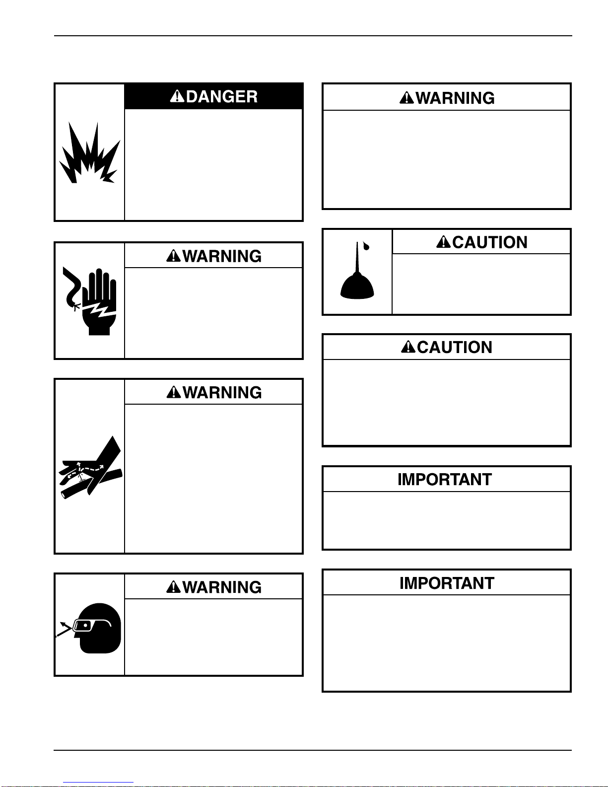
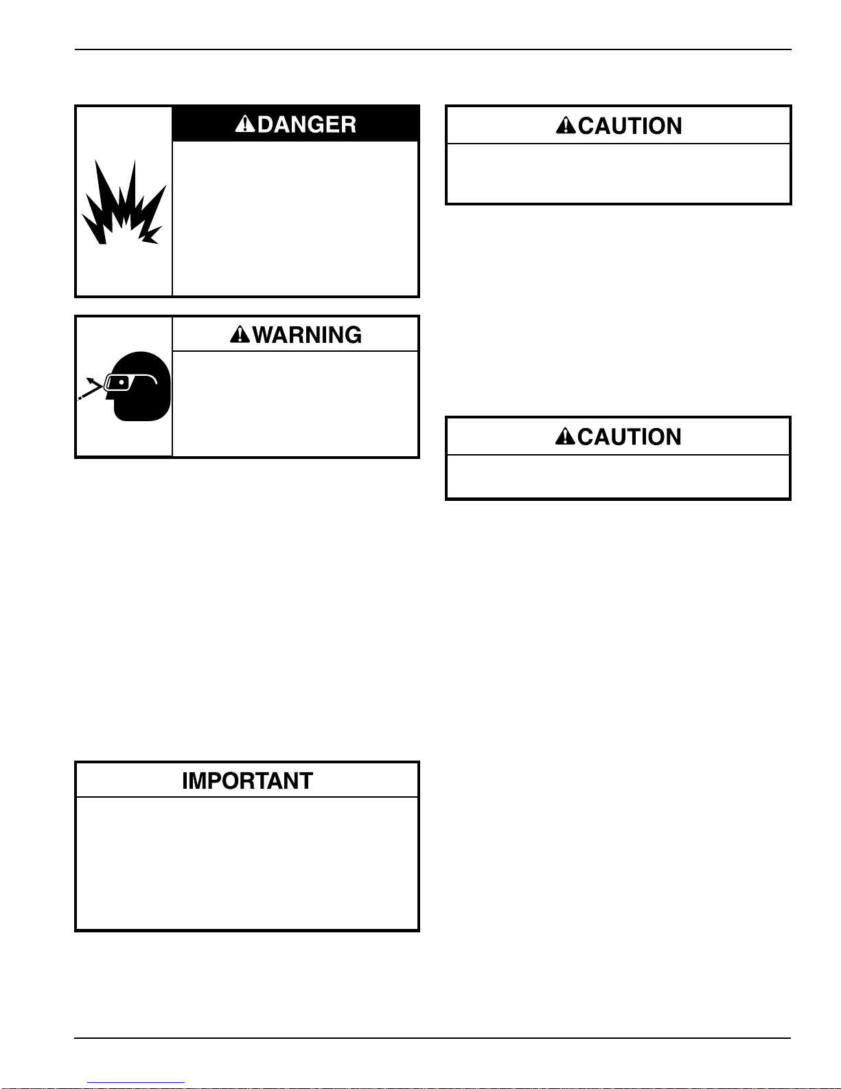
Do not use this pump in a hazard-
ous environment. Hazards include
flammable liquids, gases, or other
materials. Using this pump in a
hazardous environment can result in
a fire or explosion.
Failure to observe these warnings
will result in severe injury or death.
Wear eye protection when operating
or servicing this tool.
Failure to wear eye protection can
result in serious eye injury from
flying debris or hydraulic oil.
Operating Instructions
Procedure for depressurizing the hydraulic system:
1. Release pressure and allow the ram to retract
fully.
2. Disconnect the pump from the power source.
3. Disconnect the hose slowly to release any
trapped pressure.
Draining Oil Reservoir
Unscrew and remove 1/8" pipe plug (51) from side of
pump base. Turn pump on its side to drain all oil from
reservoir. Be sure to replace plug before refilling reser-
voir with oil.
Flushing System
As long as the pump is used as outlined in the operating
instructions, long, trouble-free performance can be
expected. To maintain this performance, it is absolutely
essential that dirt or other foreign matter be kept out
of the system as this is the most common cause of
hydraulic system failure. Therefore, when opening up
the pump for any reason, such as making pipe connec-
tions, adjusting pressure or any repair, be sure to
exercise extreme care in cleanliness and to use clean
tools and cloths. If, at any time, dirt is suspected to have
found its way into the system, the entire oil system
should be flushed as follows:
1. Drain oil from reservoir.
2. Fill reservoir with any recommended flushing oil or
clean kerosene and operate pump. Work the control
valve back and forth several times during flushing to
wash all foreign particles form the control valve unit.
Note: Do not operate pump for a very long time as
system is not designed to operate with flushing
oil or kerosene.
3. Drain flushing oil or kerosene from reservoir and refill
with new oil.
Never use synthetic fluids or fluids with poor lubri-
cating qualities (i.e., brake fluids, etc.) as permanent
injury to the pump will result.
Check to see that vent unit is not clogged before
attempting to operate pump.