Greenlee Textron / Subsidiary of Textron Inc. 54455 Boeing Dr., Rockford, IL 61109-2988 815/397-7070
940-PS Series Hydraulic Power Pumps
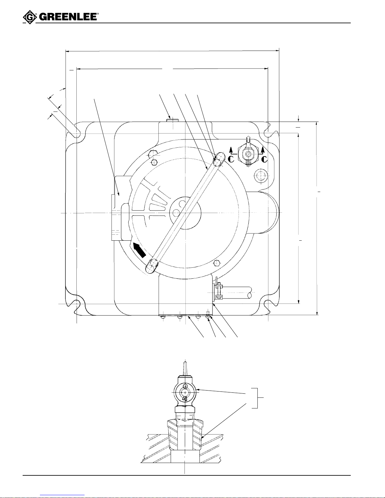
Pump Specifications
Check to see that vent unit is not clogged before
attempting to operate pump.
Never use synthetic fluids or fluids with poor
lubricating qualities, i.e., brake fluids, etc., as
permanent injury to the pump will result.
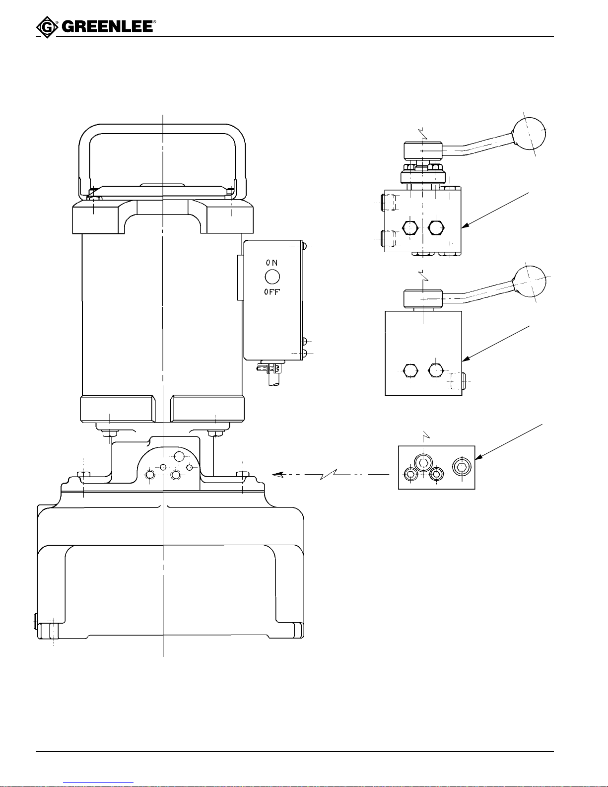
Draining Oil Reservoir. Unscrew and remove 3/8 inch
pipe plug (60) from side of pump base. Turn pump on its
side to drain all oil from reservoir. Be sure to replace
plug before refilling reservoir with oil.
Eight quarts are required of which 6-1/4 quarts are
usable. A minimum of 1-3/4 quarts must be at the
bottom of the reservoir at all times during operation.
Be sure that your complete operation does not require
more than the usable amount of oil.
To refill or add oil to the reservoir, proceed as follows:
1. Remove vent unit from top of reservoir (B).
2. Add oil to within 1/2" of top of reservoir when ram is
retracted.
3. Install vent unit (B) securely in place.
Servicing Instructions
Filling Oil Reservoir. The oil reservoir must be kept
filled with a good grade of light hydraulic oil—Greenlee
905 0806.8 hydraulic oil or equal in order or the pump to
operate properly.
Flushing System. As long as these pumps are used as
outlined in the operating instructions, long, trouble-free
performance can be expected. To maintain this perform-
ance, it is absolutely essential that dirt or other foreign
matter be kept out of the system as this is the most
common cause of hydraulic system failure. Therefore,
when opening up the pump for any reason, such as
making pipe connections, adjusting pressure or any
repair, be sure to exercise extreme care in cleanliness
and to use clean tools and cloths. If, at any time, dirt is
suspected to have found its way into the system, the
entire oil system should be flushed as follows:
1. Drain oil from reservoir.
2. Fill reservoir with any recommended flushing oil or
clean kerosene and operate pump. Work the control
handle back and forth several times during flushing
to wash all foreign particles from the control valve
unit.
Note: Do not operate pump for a very long time as
system is not designed to operate with flushing
oil or kerosene.
3. Drain flushing oil or kerosene from reservoir and
refill with new oil.
Motor Maintenance
The 1 hp or 1-1/2 hp motors used on these power
pumps, when in need of repairs, should be repaired by
the manufacturer of the motor or at one of the qualified
GE Service Stations.
TYPE H.P. VOLTS 100 P.S.I. 10,000 P.S.I.
PUMPING CAPACITY
MODEL (CU. IN. PER MIN.) HEIGHT WEIGHT
940-PS
Series
MOTOR
AC 1 115/230 150 30 20
9
/
16
" 10
1
/
2
x 12" 71 lbs. approx.
BASE
DIAMETER