S19.0.01.6C-03
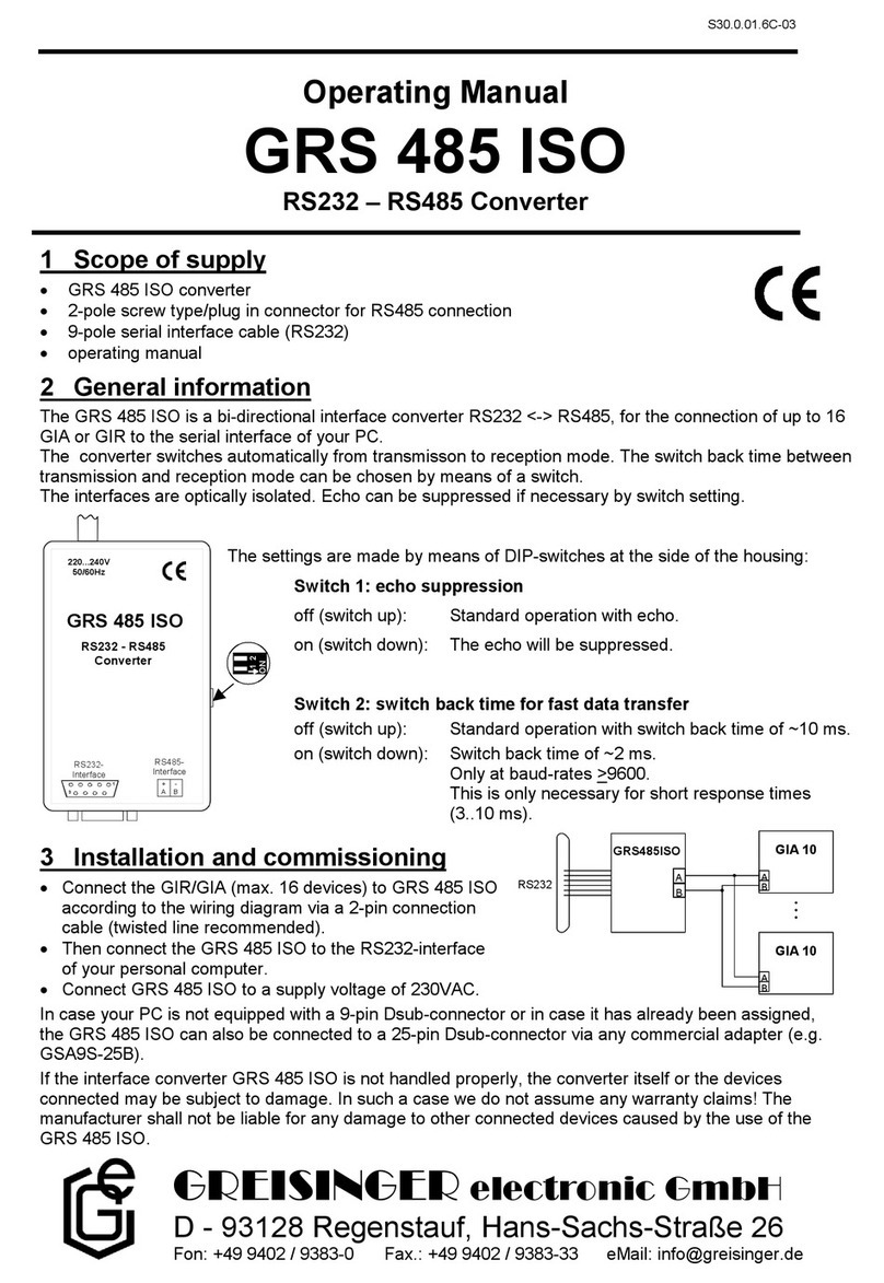
Wiring diagram:
Connection of up to 16 GIA10 or GIA1000/GIR1002 via one GRS485 to the RS232-interface of your PC:
A
BA
B
GIA 10
GRS485
A
B
GIR1002
RS232
Installation and commissioning:
Connect the GIA 10, GIA1000 or GIR1002 (max. 16 devices) to be connected with the 2 interface converter
via a 2-pin connection line (twisted line recommended) according to the information given in the wiring
diagram.
Plug power pack supplied into the GRS485 and connect it to a mains voltage of 220 - 240 VAC.
Then connect the interface converter to the RS232-interface of your PC.
(In case your PC is not equipped with a 25-pin Dsub-connector or in case it has already been assigned, the GRS485 can
also be connected to a 9-pin Dsub-connectorviaanycommercialadapter.)
If the interface converter GRS485 is not handled properly, the converter itself or the devices connected may
be subject to damage. In such a case we do not assume any warranty claims!
The manufacturer shall not be liable for any damage to other connected devices caused by the use of the
GRS485.
Operation of the RS232/RS485 –interface converter GRS485
Using the GRS485 with the GIR/GIA1xxx devices the following has to be considered:
The GRS485 is bi-directional serial interface converter for RS232<->RS485 interfaces.
The GRS485 is operating in half-duplex mode using the RTS signal of the RS232 interface for the
activation/deactivation of the transmitter. The receiver stays permanently active (echo mode).
For the communication with the GIR/GIA1xxx and GIA1 devices therefore the programmer has to follow the
following signal sequence:
1. Activation of the RTS signal (RS232 voltage level > 3V)
2. Sending of the request string to the GIR/GIA. For detailed information please refer to the users manual of
the device
3. Deactivation of the RTS signal (RS232 voltage level < 3V).
Note: The deactivation of the RTS signal must have been performed 25ms after the transfer of the
last bit of the request string!
4. Reading the response of the request string
General purpose terminal programs (e.g. Hyperterminal) do not support this method of transmit –receive swapping.
Depending on the used programming language there may be a significant effort for the implementation of the
described time critical signal swapping of the RTS signal.
An efficient way of decreasing this effort may be to use the “GRS 485 ISO”interface converter instead of the
“GRS485”.
The “GRS 485 ISO”is also a bi-directional serial interface converter for RS232 <-> RS485 conversion. In
contrast to the “GS485”converter the “GRS 485 ISO”supports automatic receive and transmit mode


