Grillo HWT 570 MULTIFORCE User manual

EN
OPERATOR’S MANUAL
02589.2022.06
HWT 570 MULTIFORCE
Wheeled string trimmer

2
1. Introduction ............................................................................ 3
2. Description and intended use............................................... 3
3. Use and safety decals............................................................ 4
4. General safety rules............................................................... 6
5. General warnings to keep in mind........................................ 7
6. Identicationofmachinecontrolsandfunctions ............... 8
7. Identicationofmachinecomponents................................. 9
8. Technicalspecications...................................................... 10
9. Operating instructions..........................................................11
9.1 Setting up the machine for use.......................................11
9.2 Checks to be carried out before starting the engine.......11
9.3 Starting the engine .........................................................11
9.4 Starting the machine.......................................................11
9.5 Tilt device....................................................................... 12
9.6 Work conclusion ............................................................ 12
9.7 Ordinary machine cleaning............................................ 12
9.8 Useful rules for correct use............................................ 12
10. Safety devices ...................................................................... 12
10.1 PTO active coupling....................................................... 12
10.2 Automatic brake on the cutting rotor.............................. 12
11. Ordinary adjustments .......................................................... 13
11.1 Handlebar setting .......................................................... 13
11.2 Cutting height adjustment.............................................. 13
12. Extraordinary adjustments.................................................. 14
12.1 Adjustment of the PTO, tilt device and handlebar
rotation lever registers ................................................... 14
12.2 Adjusting the automatic brake on the cutting rotor ........ 14
13. Ordinary maintenance ......................................................... 14
13.1 Engine maintenance...................................................... 14
13.2 Lubrication of the PTO................................................... 15
13.3 Replacement of the strings on the cutting rotor............. 15
14. Extraordinary maintenance................................................. 16
14.1 Replacement of the belt................................................. 16
15. Troubleshootingguide......................................................... 17
16. Maintenanceschedule......................................................... 17
17. Lubricationchart.................................................................. 17
18. Storage and prolonged inactivity ....................................... 18
19. Availableattachments.......................................................... 18
20. Technicalassistanceservice .............................................. 18
20.1 Assistance ..................................................................... 18
20.2 Identicationdata .......................................................... 18
20.3 Spare parts.................................................................... 18
20.4 Warranty ........................................................................ 18
20.5 How to order spare parts ............................................... 18
21. Transport warnings.............................................................. 18
22. Disposal ................................................................................ 18
EU Declaration of Conformity...................................................... 19
Translationoftheoriginalmanual.
Allinformation,illustrationsandtechnicalspecicationsinthis
manualarebasedonthelatestinformationavailableatthetime
of publication.
Subjecttochangewithoutpriornotice.
TABLE OF CONTENTS
HWT 570 MULTIFORCE Wheeled string trimmer / Translation of the original instructions

3
1. INTRODUCTION
Dear Customer,
we thank you for the trust and preference you have placed in our Grillo
HWT570MULTIFORCEandwearecondentthattheuseofyournew
machine will fully meet your requirements.
For optimal use and maintenance over time, please carefully read and
follow the instructions in this booklet; this will enable you to obtain the
best results and safeguard your purchase.
Please keep this manual, which should always accompany the machine
as an integral part of it.
Readingtheoperator’smanualisveryimportant.
2. DESCRIPTION AND INTENDED USE
The Grillo HWT 570 MULTIFORCE is a wheeled string trimmer with tilting
frameanddualPTO.Itcanbettedwiththeclassiccuttingrotor,which
isidealfortrimminggrassinatareas;alternatively,itcanbettedwith
the weeder brush kit to clean weeds from interlocking pavers and kerbs.
Any other use is considered as improper use.
This machine must only be used by personnel who are familiar with
its specic features, safety regulations and all that concerns accident
prevention.
Any improper use of the machine will invalidate the warranty and relieve
the manufacturer of all responsibility; any risk resulting from improper use
will be borne by the user.
Maintenanceandrepairofthemachinemustbecarriedoutbyqualied
personnel following the procedures specied by the manufacturer.
Any alteration or tampering will invalidate the warranty and relieve the
manufacturer of all responsibility for damage or accidents.
mArkings in the mAnuAl
This manual contains warnings highlighted in bold and marked with these
symbols:
CAUTION
This symbol and the text that follows it contain information that
highlights possible, even very serious, risks to the safety of the
operatorandanyoneworkingonthemachineiftheydonotconsider
thewritteninformationandprocedures.
IMPORTANT
This heading informs the operator of actions or conditions that
coulddamagethemachine.
Read these messages carefully to avoid injury or damage to the machine.
The retailer is responsible for inspecting the machine before delivery and
for completing the inspection form “PRE-DELIVERY INSPECTION”.
On this occasion the retailer will provide the customer with all the
information necessary to use the machine.
The customer will receive the machine in optimum condition.

4
3. USE AND SAFETY DECALS
Serial number
Sound power level
MAX
0
Throttle
MIN

5
Danger of rotating tool and
danger of objects thrown
Keep a safe
distance
Dangerofre
Protect yourself with PPEDanger of objects thrown by the
rotation of the attachment
Consult the manual before
inspecting the cutting rotor

6
4. GENERAL SAFETY RULES
Accident prevention rules
On the machine and in this manual there are warnings and indications
accompanied by this symbol:
it indicates the presence of a potential hazard for which particular caution
should be taken for your own safety and for the safety of others who may
be within the operating range of the machine.
This machine is manufactured in compliance with European regulations
and is CE marked.
All accident prevention rules in this manual are important and must be
observed. Always keep the manual handy and read it carefully to learn
how to use the machine safely. Do not allow anyone to use the machine
without having received comprehensive instructions.
explAnAtion of wArning decAls
Dangerofobjectsthrownbytherotatingtool
The cutting rotor, when driven, could dangerously hurl objects, gravel,
clippings, even at a distance.
Protect yourself with appropriate safety equipment.
Dangerofrotatingtoolandthrownobjects
Do not put hands or feet near the cutting rotor when the engine is running.
Do not work with the trimmer on gravel or foreign bodies which can be
hurled very dangerously even at a distance.
Keep a safe distance
Keep people at least 15 m away when the machine is running.
Dangerofre
Handlefuelwithcareasitishighlyammable;donotrefuelwhilesmoking,
nearopenamesorsparks,whentheengineisrunning.
personAl protection equipment
Before using the machine the appropriate personal protection equipment
must be worn: body protection, protective gloves, safety footwear, hearing
protection, goggles.

7
5. GENERAL WARNINGS TO KEEP IN MIND
WARNING:Readcarefullybeforeoperatingthemachine.
Cautionisthemainrequirementinaccidentprevention!Carefully
read the following warnings when using the machine, even
before starting work. Improper use can be dangerous. Observe
thefollowingprecautions:
• Read this manual completely before starting and running the
machine;
• Before handing the machine over to other people, make them
aware of the safety rules and how to use the machine;
• Pay particular attention to the safety decals on the machine;
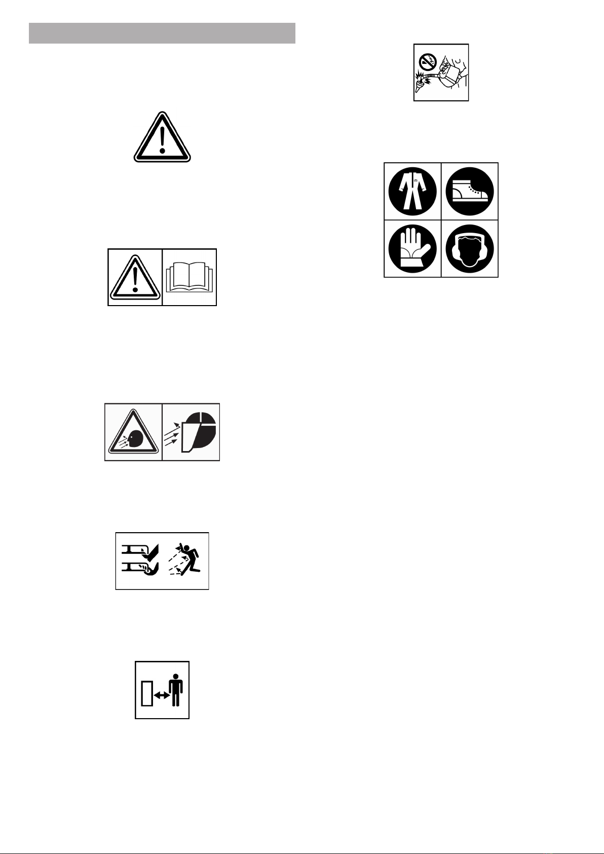
• Before starting work, always wear appropriate work wear, long
trousers, gloves, safety shoes and goggles;
• The use of hearing protection equipment is recommended when
using the machine continuously. Use earplugs or earmuffs that
comply with current regulations.
sAfety in the working environment
• Before switching on the machine, check that there are no
animals or people nearby, especially children; the minimum
distance is 15 m;
• Check the area in which the machine is to be used: before
cutting the grass, clear away all objects (stones, branches, etc.)
that could damage the machine or that could be thrown from the
rotating attachment;
• Be careful when working near a road;
• Do not operate near ditches or embankments which may
collapse under the weight of the machine, especially if the
ground surface is uneven or wet;
• Take special care when working on slopes. Do not work on steep
slopes. The handling of the machine is reduced on a slope;
• Do not use the machine in enclosed areas to avoid toxic exhaust
fumes.
driving And behAviourAl sAfety
• Do not use the machine to transport people or animals;
• Children under 16 years of age must not use the machine;
• Be careful on uneven ground;
• Onlyworkinsunlightorwithgoodarticiallight;
• Do not leave the machine on a slope;
• Do not use the machine to shred metal, plastic materials, wood
clippings or waste in general;
• Before starting to cut, check that the bolt under the rotor is
securely tightened.
further sAfety meAsures
• If you hit a foreign body, disengage the attachment, switch off
the engine, and inspect the rotor for damage. If it is severely
damaged, it must be replaced;
• If the machine begins to vibrate abnormally after a knock,
immediately carry out a general check to identify the reason
for the anomaly. If necessary, request the assistance of an
authorised Grillo workshop;
• The rotation of the cutter rotor is very dangerous, never put your
hands or feet near the rotor while the engine is running;
• The guards installed on the machine (bonnets, plastics, etc.)
must not be removed when working;
• Before starting work, check that all safety devices are in working
order. Do not tamper with or deactivate them;
• Do not operate the machine barefoot; keep feet well clear of the
rotor;
• Before checking, adjusting, repairing or simply cleaning the
machine, disengage the rotor and switch off the engine;
• Do not change the engine settings, especially the maximum revs;
• Do not have anyone check the machine while you are driving with
the engine running.
fuel And fire hAzArd
• Only refuel outdoors, always switch off the engine, stay away from
sparks or ames, do not smoke! Securely replace tank and fuel
container caps;
• Avoidfuelspills.Afterllingthetankcleanupanyspillageonthe
machine before starting the engine;
• Storefuelincontainersspecicallydesignedforthispurpose;
• If it is necessary to empty the tank, do so outdoors or in a ventilated
area;
• Caution!Toreducetheriskofre,alwayskeeptheengine,mufer,
exhaust manifold, fuel tank area and fuel line clean and free of
grass, leaves and dust;
• Do not store the machine in buildings where the fuel vapours could
reachamesandsparks;
• Allow the engine to cool down before storing the machine in an
enclosed area.
sAfe replAcements
• A deformed or damaged rotor must always be replaced, never
repaired;
• Always use genuine Grillo spare parts and accessories;
• Grillo machines are designed for the use of genuine Grillo
accessories or accessories from authorised manufacturers. Do not
install non-genuine accessories, accessories from unauthorised
manufacturers,oraccessoriesmodiedbyunauthorisedpersonnel
on your machine.

8
1. THROTTLE
2. ADJUSTER ON PTO LEVER
3. SAFETY LOCK ON PTO LEVER
4. PTO LEVER
5. HANDLEBAR ROTATION LEVER
6. ADJUSTER ON HANDLEBAR ROTATION LEVER
7. ADJUSTER ON TILT DEVICE LEVER
8. TILT DEVICE LEVER
9. HANDLEBAR HEIGHT ADJUSTMENT LEVER
6. IDENTIFICATION OF MACHINE CONTROLS AND FUNCTIONS
1 2 3 4
568
9
7

9
1. ENGINE OIL LEVEL CAP
2. RECOIL KNOB
3. FUEL TANK CAP
4. ENGINE AIR FILTER
5. ENGINE GUARD
6. UPPER PTO COVER
7. INSPECTION AND MAINTENANCE OPENINGS
8. LOCKING NUT AND GRUB SCREW ON LOWER PTO
9. GRASS ANTI-WINDING DISC
10. CUTTING ROTOR
11. RUBBER GUARD
12. CUTTING AREA GRASS GUARD
13. SIDE GRASS GUARD
7. IDENTIFICATION OF MACHINE COMPONENTS
32 41
6
5
78
10
9
1211 13

10
8. TECHNICAL SPECIFICATIONS
MODEL:TRIMMERHWT570MULTIFORCE,wheeledstringtrimmer
withtiltingframeanddualPTOforattachmentchange.
ENGINE: BRIGGS&STRATTON 575EX, 140 cm³, 2,2 kW (3 HP) at 3200
rpm, single-cylinder, petrol engine.
FUEL TANK CAPACITY: 0,8 litres
STARTER: breakaway with recoil starter, Ready Start.
DRIVE SYSTEM: handlebar adjustable in height, tiltable to the right and
left, foldable.
SAFETY DEVICES: active coupling (immediate stop of the attachment
when the lever is released).
TILT DEVICE: control of frame tilt via lever from the handlebar.
WHEELS: 16’’ (Ø41 cm), non-driving wheels.
CUTTING ROTOR: at 3600 rpm, clockwise.
CUTTING WIDTH: 60 cm
CUTTING HEIGHT: adjustable at 1,5 - 3 - 5 - 6 cm.
DIMENSIONS(g.1):
- Width (A): 61 cm
- Width at the wheels (B): 55 cm
- Length (C): 145 cm
- Height (D): 97 cm – 121 cm (handlebar at min and max height)
WEIGHT: 46 kg
AVAILABLE ATTACHMENTS: weeder brush with steel strands.
C
B
A
D
Fig. 1

11
9. OPERATING INSTRUCTIONS
9.1 SETTING UP THE MACHINE FOR USE
• Check the integrity of the machine to ensure that it has not been
damaged during transport;
• Remove the machine from its packaging, taking care not to damage
theleversandcables.Useanappropriatehoistofsufcientcapacity
for the weight of the trimmer;
• Raise the handlebar using the height adjustment lever and rotate it
to the driving position using the handlebar rotation lever (ref. 11.1
Handlebar setting);
• Fittheengineguardusingtheboltsprovided(g.2);
• Fitthesidegrassguard(g.3).
Fig. 2
Fig. 3
9.2 CHECKS TO BE CARRIED OUT BEFORE
STARTING THE ENGINE
IMPORTANT:theengineoilmustbelledbeforestartingthe
machine.Followtheinstructionsintheenginemanual.
Before using the machine, check that:
1. The engine oil is level;
2. Theairlterisclean;
3. Thereissufcientfuelinthetank;
For detailed oil level check see 13. Ordinary maintenance.
9.3 STARTING THE ENGINE
1. Setthethrottletomaximumrevs(g.4/MAX);
2. Slowly pull the recoil starter knob from the base (g. 5) until
resistance to pulling is felt;
3. From the point of resistance, pull the knob vigorously. The engine
will start;
4. If the engine does not start, repeat from step 2 or verify the checks
to be carried out before starting the engine.
0
MIN
MAX
Fig. 4
Fig. 5
9.4 STARTING THE MACHINE
CAUTION: before starting work, always wear appropriate work
wear,gloves,safetyshoesandgoggles.
1. Adjust the height of the handlebar and carry out the checks listed
above (ref. 9.2 Checks to be carried out before starting the engine);
2. Insert the strings into the rotor and check their length, so that they
do not hit parts of the machine during rotation, thus damaging it
(ref. 13.3 Replacement of the strings on the cutting rotor);
3. Start the engine and move the throttle to maximum revs (g. 4/
MAX);
4. To activate the cutting rotor, press in sequence the PTO lever
safetylock(g.6/A),thentheredPTOlever(g.6/B).Themachine
will start cutting;
5. Tostopit,simplyreleasetheredPTOlever(g.6/B),whichwill
returntotheSTOPposition,withthesafetylock(g.6/A)engaged
again.
CAUTION:whentherotorisinoperation,neverputhandsor
feetinthecuttingarea.Maintainallguardsinplacetoallowsafeuse
ofthemachine.
B
A
C
Fig. 6

12
9.5 TILT DEVICE
Insomesituations,suchastrimmingedgesornishingnearwalls,itmay
be useful to cut close to the ground. To achieve this there is the TILT
device:byoperatingthelevertotheleftofthehandlebar(g.6/C)itis
possible to release the frame from the central position and tilt it to the
right or left, accompanying the tilt with the handlebar. In this operating
modetherotorwillperformaninclinedcut(g.7,tiltstotheright,leftand
centre position).
Fig. 7
In order to achieve a cut grazing the ground, it is advisable to t the
strings in the lowest setting, with the string holder plate upside down (ref.
11.2 Cutting height adjustment).
9.6 WORK CONCLUSION
When cutting is complete release the PTO lever, then:
1. Move the machine out of the working area;
2. Switchofftheenginebymovingthethrottletothe‘0’position(g.
4/0).
9.7 ORDINARY MACHINE CLEANING
CAUTION: before starting any cleaning operation, always wear
suitableclothingandprotectivegoggles.
CAUTION:whencleaningthecuttingrotor,alwaysensurethat
theengineisswitchedoff.
IMPORTANT:inordertoreducetheriskofre,itisimportant
to keep the engine and muffler area clean of dust and dry grass
residues.
At the end of each job, proper cleaning ensures a long service life for the
machine and prevents most common inconveniences.
The best way to clean the machine is with compressed air in the engine
area and optionally water for the body parts and rotor area.
IMPORTANT: avoid wetting the engine linkages, cables and
handlebarleverswithastrongjetofwater.
9.8 USEFUL RULES FOR CORRECT USE
The machine will work in optimum conditions if certain precautions are
followed.
• Before starting work, check that the rotor and grass guard are
perfectly clean, free of grass and dirt;
• Keep cables and levers always clean of dirt and dust;
• Check the ground for stones, large branches and foreign bodies
before cutting the grass. If possible, remove them;
• Check often the length of the strings: they must not be damaged
andmustbettedcorrectly(ref.13.3Replacementofthestrings
on the cutting rotor);
• Be careful when cutting the grass and slow down if there are
obstacles or areas of very tall grass;
• Pay attention if the engine revs decrease: working is overloaded,
it is necessary to reduce forward speed or cut the grass in several
passes for greater effectiveness;
• The best performance with the trimmer is obtained with strings at
the correct length; furthermore, the square or angular cross-section
of the string will result in less cutting effort;
• Thebestcuttingconditionisonatground.Ifyoucutonaslopebe
careful, as the handling of the machine is reduced.
CAUTION:avoidslopesthataretoosteep;forcorrectoperation
ofthemachineandforsafety,observetheslopelimitsoftheengine:
max 24°.
10. SAFETY DEVICES
10.1 PTO ACTIVE COUPLING
The machine is equipped with an active coupling system for the operation
of the PTO.
Therefore, to stop the cutting rotor when in operation, simply release the
correspondingredlever(g.6/B).
CAUTION:checkfrequentlythattheactivecouplingfunctions
correctly. When releasing the PTO lever, the rotor must stop
immediately.
If the rotor does not stop immediately, check the lever register adjustment
(ref. 12.1 Adjustment of the PTO, tilt device and handlebar rotation lever
registers) or contact the service centre.
10.2 AUTOMATIC BRAKE ON THE CUTTING ROTOR
The cutting rotor is equipped with a brake system that, when the red PTO
lever(g.6/B)isreleased,ensuresthattheattachmentstopswithin1-2
seconds. If the attachment does not stop immediately, check the brake
adjustment (ref.12.2 Adjusting the automatic brake on the cutting rotor) or
contact the service centre.

13
11. ORDINARY ADJUSTMENTS
11.1 HANDLEBAR SETTING
Before starting work, it is recommended to position the handlebar in the
most comfortable position and with the greatest control over the machine.
To adjust the height of the handlebar, push down the lever located at the
baseofthehandlebar(g.8),thenmovethehandlebarupordown.To
lock the handlebar in the desired position, release the lever, making sure
that its central pin engages in the notch.
Fig. 8
In certain cutting conditions, such as clearing edges, it may be useful
to rotate the handlebar to the right or left. To rotate it, simply use the
appropriatelever(g.9):bypressingit,thehandlebarcanrotatefreely
and it will be possible to move it to the right, to the left, or to make a
half turn so that it is in the transport position. By releasing the lever, the
column will lock into the corresponding holes in the base.
Fig. 9
11.2 CUTTING HEIGHT ADJUSTMENT
Itispossibletotthestringholderplateintwocongurations(g.10/A
and 10/B).
• Conguration A allows tting the strings in positions 1 and 2.
Position 1 is the lowest and allows a grazing cut to the ground.
• Conguration B allows tting the strings in positions 3 and 4.
Position 4 is the highest.
A B
2
1 3
4
Fig. 10
To switch from congurationA to conguration B and vice versa, it is
necessarytoundotheboltlocatedunderneaththecuttingrotor(g.11).
Fig. 11
CAUTION:iftherearestonesorsmallobstaclesinthecutting
area,itisadvisabletokeepthestringholderplateinconguration
Bforpositions3and4.Thiswilllimitimpactsanddamagetothe
cutting rotor.

14
12. EXTRAORDINARY ADJUSTMENTS
CAUTION:theadjustmentproceduresdescribedbelowrequire
technicalskillsandexpertise.Itisadvisabletocontactanauthorised
Grillocentretocarrythemout.
12.1 ADJUSTMENT OF THE PTO, TILT DEVICE AND
HANDLEBAR ROTATION LEVER REGISTERS
Keeping the levers at the correct tension ensures proper operation of the
machine controls.
By loosening the lock nut and unscrewing or screwing the relevant
adjuster, it is possible to adjust the tension of the cable connected to the
leverofthetiltdevice(g.12/A),thehandlebarrotation(g.12/B)andthe
PTO(g.12/C).
CA B
Fig. 12
12.2 ADJUSTING THE AUTOMATIC BRAKE ON THE
CUTTING ROTOR
To access the brake on the cutting rotor, remove the front cover of the
machine. If, when releasing the PTO lever, the cutting rotor does not stop
immediately, then slightly unscrew the nut on the threaded rod connected
tothebrake(g.13).If,ontheotherhand,whenpressingthePTOlever
the brake pad remains too close to the pulley, causing it to keep friction
during the rotation of the rotor, then further tighten the nut on the threaded
rodconnectedtothebrake(g.13).
Fig. 13
13. ORDINARY MAINTENANCE
CAUTION:ifliftingthemachineoranypartofit,alwaysuse
suitabletoolssuchassupportsorsafetycatches.
• Alwayswearsuitableclothingandworkglovesbeforestarting
anycleaning,maintenanceorrepairwork;
• Donotleavethemachineduringmaintenancewithoutsafety
devices or lifted, in places accessible to inexperienced people,
especiallychildren;
• Neverdispose of used oil, fuel or any other pollutant in the
environment!
• Regular maintenance helps to keep the machine in perfect
working order.
13.1 ENGINE MAINTENANCE
CAUTION: before carrying out any inspection and maintenance
operation,makesurethattheengineisswitchedoff.
IMPORTANT: read the engine manual; check the engine
periodically,keeptheairltercleanandtheengineoillevel.
engine Air filter
Checkandcleantheairlter(g.14)every8hours.
If the cartridge is very clogged, replace it. Avoid cleaning the cartridge
with air jets.
Ifworkinginverydustyenvironments,itisadvisabletocleantheairlter
every 4 hours or as needed.
Fig. 14

15
engine oil
IMPORTANT:itisessentialtochangetheoilafterthebreak-in
period(rst5hours).Thenchangetheoilevery50hoursoroncea
year.
Tochecktheoillevelusetheoildipstick(g.15)whentheengineiscold.
To change all the oil in the engine, use SAE30 oil in a quantity of 0.44
litres.
Fig. 15
13.2 LUBRICATION OF THE PTO
CheckthelowerPTOevery50hoursbyundoingthelocknut(g.16/A)
andthegrubscrew(g.16/B)locatedabovethecuttingrotor.Lubricate
with grease.
If the weeder brush attachment is used, also check the upper PTO (ref.
Weeder brush manual).
A
B
Fig. 16
13.3 REPLACEMENT OF THE STRINGS ON THE
CUTTING ROTOR
For an optimal cut, check the length of the strings often: they must not be
damagedandmustbettedcorrectly.
• Werecommendinsertingthesinglestringusingallfourholes(g.
17) so that it does not accidentally slip out during cutting;
• Always check the correct length: before starting the rotor, check
that the strings do not hit the frame or guards.
Fig. 17

16
14. EXTRAORDINARY MAINTENANCE
CAUTION: the operations contained in this chapter require
technicalskillsandspecialequipment.
ItisadvisabletocontactanauthorisedGrillocentre.
14.1 REPLACEMENT OF THE BELT
IMPORTANT: use only genuine Grillo belts.
To replace the belt:
1. Remove,asshowning.18:thegrassguard(A),thecoverunder
the machine (B), the covers on the sides of the frame (C) and the
front cover (D). This will allow access and greater visibility of the
inside of the machine during maintenance;
A
B
C
D
Fig. 18
2. Remove the belt guide (g. 19/A) by undoing the two bolts (g.
19/B);
B
A
Fig. 19
3. RemovetheupperPTOcover(g.20/A),undothefourboltsofthe
centringplate(g.20/B)andthenremovethecentringplate(g.
20/C) from the cutting rotor shaft;
B
C
A
Fig. 20
4. The belt can now be removed and replaced with a new one;
5. Reassemble the centring plate and belt guide, making sure that the
beltisinsertedinthegrooveofthedrivepulleyandinsidethens
of the belt guide;
6. Retallcovers.

17
15. TROUBLESHOOTING GUIDE
HWT570MULTIFORCE-TROUBLESHOOTINGGUIDE
PROBLEM CAUSE SOLUTION
The engine does not start
Out of fuel - Check the fuel level
Combustion issues
- Cleanorreplacetheairlter
- Check that the carburettor jets are clean
- Check that the spark plug gives a spark
Throttle is set to “0” - Set the throttle to MAX
The engine starts, but
the cutting rotor does not
operate
InsufcientcabletensionofthePTOlever - Act on the PTO lever adjuster, increasing the tension of
the connected cable
The engine does not
switch off
Throttle not in “0” position - Bring the throttle to the “0” position
The throttle is not properly connected to the engine - Check the throttle and its connection to the engine
Drop in engine
performance during cutting Overload - Proceed with cutting in small areas, avoiding cutting in
areas with many residual shrubs
When the cutting rotor is
activated, the engine shuts
down
Rotor jammed by an obstruction, or by wound grass
- Check for obstacles jamming the rotor and remove
them
- Check the automatic brake on the cutting rotor
CAUTION:ifproblemspersistaftercarryingouttheactions
describedinthismanual,contacttheauthorisedservicecentre.
Never attempt to carry out major repairs without having the
necessarymeansandtechnicalexpertise.
IF YOU HIT A STONE OR ANOTHER FOREIGN BODY
1. Disengage the cutting rotor;
2. Switch off the engine;
3. Tilt the machine lifting the cutting rotor;
4. Check the integrity of the rotor plate, strings and metal guard.
16. MAINTENANCE SCHEDULE
HWT570MULTIFORCE-MAINTENANCESCHEDULE
MAINTENANCE ITEM FIRST 5 HOURS EVERY 8 HOURS
EVERY 50 HOURS
OR
ONCE A YEAR
EVERY 100 HOURS
Engine oil Check the level ●
Change ● ●
Airlter Check ●
Replace *
Check that the engine intake grid is clean ●
Grease the PTO ●
●recommended task
*task to be carried out if necessary
17. LUBRICATION CHART
HWT570MULTIFORCE-LUBRICATIONCHART
Engine oil SAE30 0,44 L Changeaftertherst5hoursofworkandevery50hoursthereafteror
once a year

18
18. STORAGE AND PROLONGED INACTIVITY
Store the machine in a dry place, protected from the elements.
Clean the machine of dirt and grass residues and if possible cover it with
a tarpaulin when the engine is cold. If the machine is not to be used for an
extended period of time (more than 1 month), drain the fuel.
19. AVAILABLE ATTACHMENTS
weeder brush with steel strAnds
TheweederbrushisanattachmentfortheupperPTO(g.21).
Fig. 21
It is the ideal accessory for cleaning interlocking pavers, removing weeds,
moss and dirt in general.
20. TECHNICAL ASSISTANCE SERVICE
20.1 ASSISTANCE
This manual provides instructions for the use of the machine and for its
routine maintenance.
Forextraordinarymaintenance,foralloperationsrequiringtechnical
skillsandexpertise,pleasecontactyourauthorisedGrillodealer.
20.2 IDENTIFICATION DATA
If it is necessary to contact an authorised service centre, for maintenance
information, always provide:
machinemodel ........................................................................................
serial number...........................................................................................
The machine’s serial number plate is located on the right-hand side of the
frame(g.22).
Machine model
Serial number
Fig. 22
Weadvisethecustomertonotedownthisadditionalinformationin
thespacesbelow.Itmaybeusefulfortheservicedepartment.
PURCHASE DATE ....................................................................................
GRILLO DEALER......................................................................................
20.3 SPARE PARTS
It is recommended to use only genuine spare parts, which are the only
ones that provide safety and interchangeability.
20.4 WARRANTY
Thewarranty is providedin the mannerand within thelimits specied
by current law. The retailer must hand over the machine’s warranty
certicatetotheendcustomer,printingacopyoftheregistrationfromthe
Grillowebsite.Fortheengine,theconditionsspeciedbytherespective
manufacturers apply.
20.5 HOW TO ORDER SPARE PARTS
Contact our authorised centres.
Please indicate the serial number of the machine and the code of the
component to be replaced.
It is possible to identify the part number by consulting the Grillo website:
the spare parts tables of the machine will be available by entering the
serial number.
21. TRANSPORT WARNINGS
CAUTION:makesuretheengineisswitchedoff.
lifting And trAnsport
The trimmer may not be driven on public roads. If the machine is loaded
onto a transport vehicle, secure it properly with ropes and lower the
handlebar if necessary. When lifting, ensure that cranes, hoists and ropes
havesufcientliftingcapacityfortheweightofthemachine.
22. DISPOSAL
Waste products such as waste oil or fuel, used lubricants, lters, or
other such consumable parts can cause harm to people, animals and
the environment. They must therefore be disposed of properly. Contact a
recycling centre or your retailer for information on correct disposal.

19
EU DECLARATION OF CONFORMITY
EU DECLARATION OF CONFORMITY / DICHIARAZIONE DI CONFORMITÀ UE
/ DÉCLARATION UE DE CONFORMITÉ / EU-KONFORMITÄTSERKLÄRUNG / DECLARACIÓN UE DE CONFORMIDAD
(2006/42/CE, II A)
The undersigned / Io sooscrio / Je soussigné / Der Unterzeichner / Yo suscrito Ing. Andrea Pinza
authorised ocer of: / in qualità di legale rappresentante della dia: / en qualité de représentant légal de la: / als rechtlicher Vertreter der Firma: /
en calidad de legal representante de la: GRILLO SPA – Via Cervese, 1701 – 47521 CESENA (FC) – ITALY
Hereby ceres that the underwrien machinery: / Dichiaro che la macchina soo indicata: / Cere que la machine indiquée ci-dessous: /
Bescheinigt, dass die unten genannte Maschine: / Cerco que la máquina indicada a connuación:
Model
Modello
Modèle
Modell
Modelo
Funcon
Funzione
Dénominaon
Bezeichnung
Función
Serial number
N° di serie
N° de série
Seriennummer
Número
HWT 570 MULTIFORCE
String trimmer / Decespugliatore a lo
/ Débroussailleuse à l / Fadenmäher /
Desbrozadoras de hilo
>709503
Is in compliance with the relevant provisions of the Direcve: / Rispea le disposizioni pernen della Direva: / Sasfait à l’ensemble des
disposions pernentes de la Direcve: / Allen einschlägigen Besmmungen dieser Richtlinie entspricht: / Cumple con todas las disposiciones
aplicables de la presente Direcva:
2006/42/CE
2000/14/CE - 2005/88/CE
Grillo S.p.A. Via Cervese 1701- 47521 Cesena (FC)- Italy
Measure sound pressure at the operator’s ear / Pressione sonora misurata all’orecchio dell’operatore / Niveaux sonores au niveau des oreilles de l’ulisateur /
Gemessener Schalldruck am Ohr des Nutzers / Presión acúsca medida a la oreja del usuario
Model
Modello
Modèle
Modell
Modelo
Sound pressure
Pressione sonora
Niveau sonore
Schalldruck
Presión acúsca
HWT 570 MULTIFORCE 84 dBA
Values determined according to / Valori determina in accordo a / Niveaux sonores selon / Werte besmmt gemäß / Valores determinados conforme a UNI EN ISO 11200:2020
Vibraons / Vibrazioni / Vibraons / Schwingungen / Vibraciones
Model
Modello
Modèle
Modell
Modelo
Le hand/arm
Mano/braccio sinistro
Main/bras gauche
Hand/Arm links
Mano/Brazo izquierdo
Right hand/arm
Mano/braccio destro
Main/bras droit
Hand/Arm rechts
Mano/brazo derecho
HWT 570 MULTIFORCE 4.87 m/s23.32 m/s2
Sound power level / Potenza sonora / Niveaux sonores / Schallleistung / Potencia acúsca
Model
Modello
Modèle
Modell
Modelo
Guaranteed sound power level
Potenza sonora garanta
Puissance sonore garane
Garanerte Schallleistung
Potencia acúsca garanzada
HWT 570 MULTIFORCE 100 dBA
UNI EN ISO 3744:2010Values determined according to / Valori determina in accordo a / Niveaux sonores selon / Werte besmmt gemäß / Valores determinados conforme a
and to Direcve / e alla Direva / et selon la Direcve / und der Richtlinie / y la Direcva 2000/14/CE
Cesena, 20/07/2021
Authorised person to draw up the declaraon on behalf of the manufacturer: / Persona autorizzata a redigere la dichiarazione a nome del
fabbricante: / Personne autorisée à constuer la declaraon au nom du fabricant: / Ermächgte Person zur Ausfergung der Erklärung im Namen
des Herstellers: / Persona facultada para redactar el cercado en nombre del fabricante:
Ing. Pinza Andrea
GRILLO SPA – Via Cervese, 1701 – 47521 CESENA (FC) – ITALY
Managing Director / Amministratore Delegato / Directeur Général / Stellvertretender Geschäsführer / Director Adjunto

The spare parts catalogues are available on line at hp://www.grilloagrigarden.co.uk/spare_parts_lists
Le tavole ricambi sono disponibili online all’indirizzo hp://www.grillospa.it/tavole_ricambi
Les vues éclatées son disponibles en ligne sur hp://www.grillofrance.fr/vues_eclatees
Die Ersatzteillisten sind online verfügbar unter hp://www.grillodeutschland.de/ersatzteillisten
Los despieces son disponibles on line en hp://es.grillospa.it/despieces
Grillo S.p.A.
VIA CERVESE 1701 - 47521 CESENA - ITALIA
Tel: (+ 39) 0547633111
Website: www.grillospa.it
E-mail: [email protected]
Grillo Deutschland GmbH
GUNTERSRIETHER STR.14 - 91224 HARTMANNSHOF - DEUTSCHLAND
Tel: (+ 49) 09154949216
Webseite: www.grillodeutschland.de
E-Mail: [email protected]
Grillo Agrigarden Ltd
DOVE FIELDS UTTOEXETER - ST148HU STAFFORDSHIRE - UNITED KINGDOM
Tel: (+ 44) 01889569149
Website: www.grilloagrigarden.co.uk
E-mail: info@grilloagrigarden.co.uk
Grillo Australasia Pty Ltd
14 REBECCA COURT - VIC 3943 SORRENTO - AUSTRALIA
Tel: (+ 61) 0428206225
Website: www.grilloaustralia.com.au
E-mail: [email protected]
AGRIGARDEN MACHINES
Table of contents
Other Grillo Trimmer manuals
Popular Trimmer manuals by other brands

McGREGOR
McGREGOR MCH1851 Original instruction manual

EINHELL
EINHELL GC-HC 9024 T Original operating instructions

Haussmann
Haussmann 68125135 Operator's manual

sunjoe
sunjoe TRJ609E Operator's manual

FLORABEST
FLORABEST FRTA 20 A1 Translation of the original instructions

GAMA
GAMA GT527 BARBER STYLE user manual