4Specications are subject to change without prior notication From serial number 7027
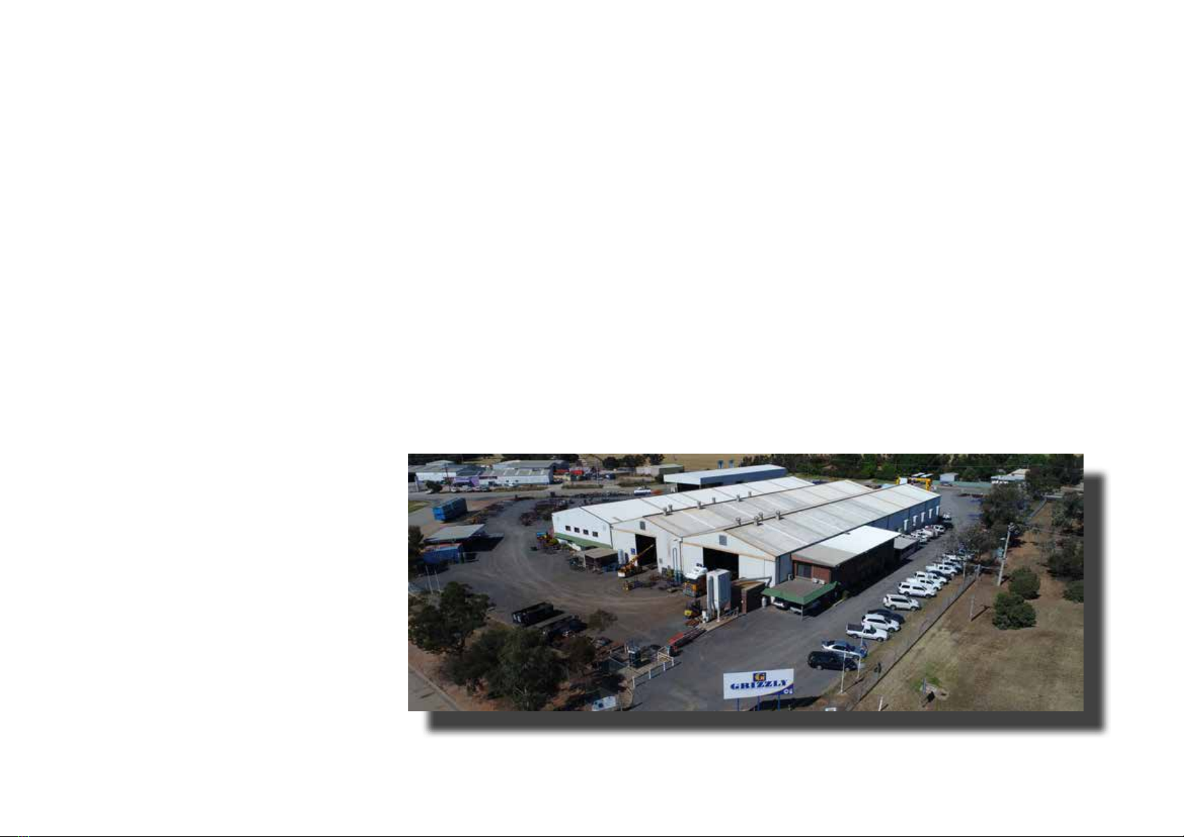
Factory and Head Oce located in Swan Hill Victoria Australia
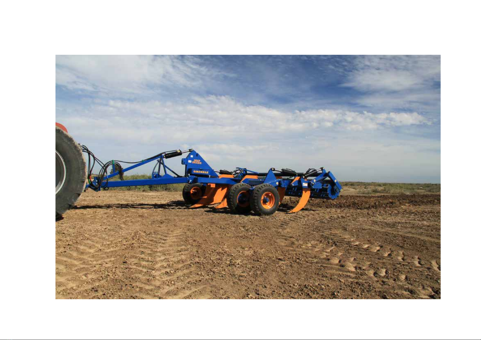
2 Welcome to Grizzly
This manual includes safety, assembly, setting
up and operating instructions, as well as
lubrication, maintenance and problem solving
instructions, disc warranty guidelines and
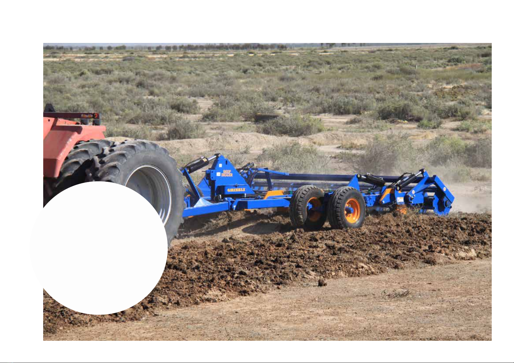
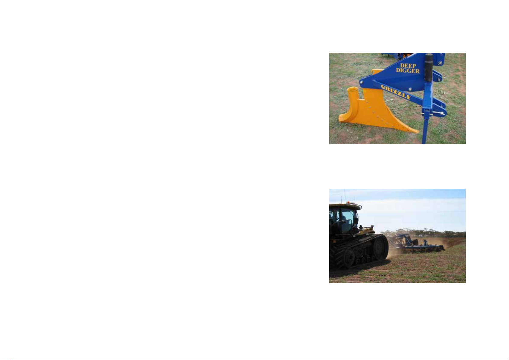
assembly drawing and parts for the Deep
Digger range of machines.
Some components explained in this manual
may not be installed on your machine.
Replacement manuals are obtainable from
your Grizzly dealer.
CompanyProle
Australia’s largest manufacturer and exporter
of Disc ploughs, Grizzly Engineering Pty
Ltd is an Australian owned and operated
manufacturing company based at Swan Hill in
Victoria.
Like many other Australian icons of ingenuity,
the Grizzly plough was founded on need.
The Grizzly name was established in the
early 1980’s by country people with the will to
construct a better oset disc plough.
In 1983, a unique three gang, tandem oset
disc design was patented and released. This
innovative Grizzly plough provided complete
ploughing out (no unworked ridges), less
working draught, elimination of side draught
and longer disc life. Other new features, at
that time, included self phasing wheel lift and
improved scrapers.
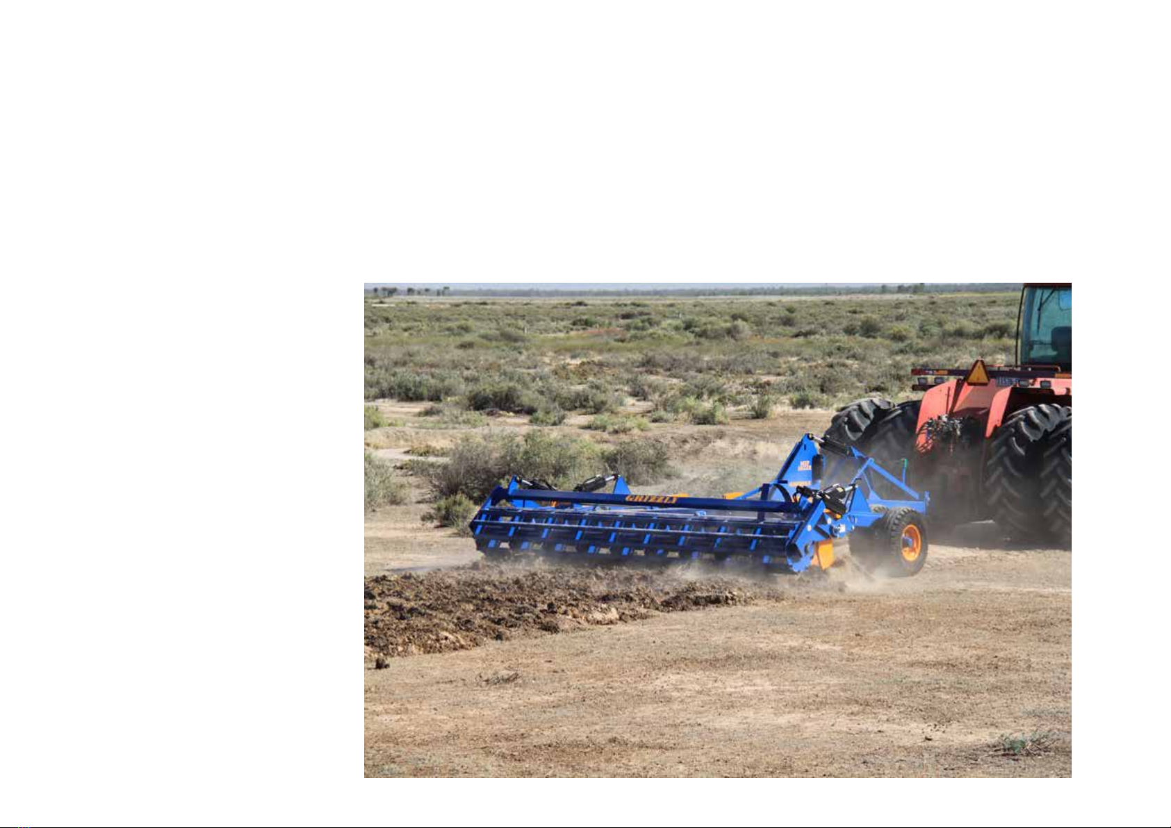
Grizzly’s broad range of versatile ploughs
suit a wide variety of agricultural applications.
Sizes vary from 1.4 metres to 15.6 metres
working width.
Grizzly also manufacture Bankers,
Renovators, and a large range of subsoil and
row crop Rippers from 1 tine.
Advantages of Grizzly technology include
lower power requirements, signicant fuel
savings, reduced stress on components,
reduced maintenance costs, and greater
operator control allowing eortless
adjustments for better performance.
The Grizzly product has earned a reputation
of uncompromising strength, performance and
reliability.
Each model is designed with inbuilt durability,
and accuracy, Eciency and easy operation
for sustainable farming practices.
Continued investment into research and
development plays a key role in the success
of the company’s product range
The company has a very successful and
loyal dealer network throughout Australia.
All dealers are backed by Grizzly training,
technical support and rapid delivery parts
replacement anywhere in Australia.