HR4004D-4504D
62. - Contents
KN208JGB_C
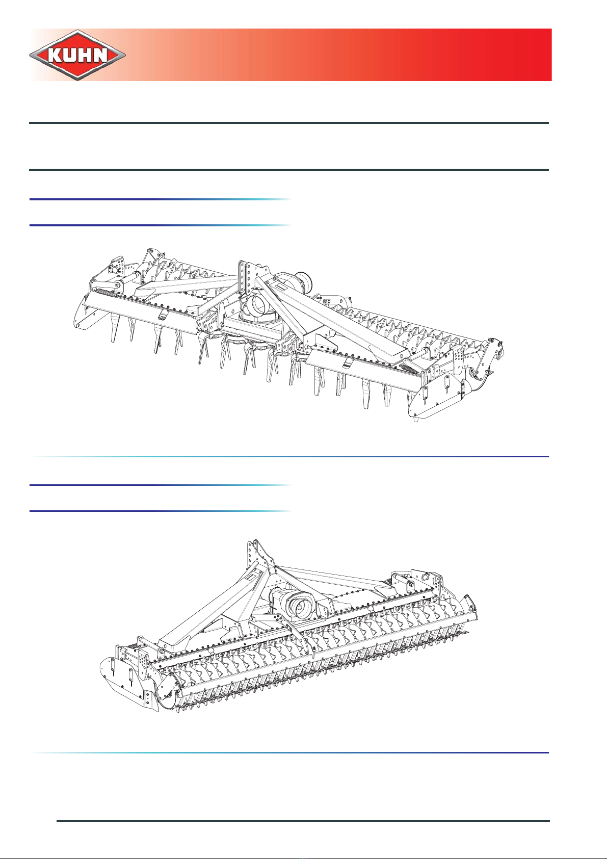
Power harrow
9. Optional equipment......................................................................................................63
9.1 Sets of gearwheels ........................................................................................................................ 63
9.2 Standard linkage............................................................................................................................ 64
9.2.1 Adjustment........................................................................................................................ 65
9.3 Hydraulic lift linkage....................................................................................................................... 65
9.3.1 Location and description of safety decals on the machine............................................... 66
9.3.2 Coupling and uncoupling.................................................................................................. 67
9.4.3 Removal ...........................................................................................................................77
9.4.4 Putting the machine into transport position ...................................................................... 78
9.3.5 Maintenance.....................................................................................................................72
9.3.6 Storage............................................................................................................................. 73
9.4 Rear attachment with double acting hydraulic lift........................................................................... 73
9.4.1 Location and description of safety decals on the machine............................................... 74
9.4.2 Coupling device................................................................................................................ 74
9.4.3 Removal ...........................................................................................................................77
9.4.4 Putting the machine into transport position ...................................................................... 78
9.4.5 Putting the machine into work position............................................................................. 79
9.4.6 Adjustments in working position ....................................................................................... 79
9.4.7 Maintenance.....................................................................................................................81
9.4.8 Storage............................................................................................................................. 81
9.5 Track eradicators........................................................................................................................... 82
9.5.1 Uncoupling the machine................................................................................................... 82
9.5.2 Adjustments in working position ....................................................................................... 83
9.5.3 Safety ............................................................................................................................... 84
9.5.4 Maintenance.....................................................................................................................84
9.6 Rear signalling elements................................................................................................................ 85
9.7 Lights and indicators...................................................................................................................... 85
9.7.1 Coupling and uncoupling.................................................................................................. 85
9.8 Lateral signalling equipment.......................................................................................................... 86
9.8.1 Instructions specific to France.......................................................................................... 86
9.9 Front signalling elements............................................................................................................... 86
9.9.1 Coupling and uncoupling.................................................................................................. 87
9.10 USA signalling equipment.............................................................................................................. 87
9.11 Front or rear levelling bar............................................................................................................... 88
9.11.1 Adjustments in working position....................................................................................... 88
9.12 Universal arm kit............................................................................................................................ 89
9.13 Adaptation parts for VENTA LC .....................................................................................................90
10. Maintenance and storage ............................................................................................91
10.1 Frequency chart............................................................................................................................. 91
10.2 Cleaning the machine.................................................................................................................... 92