Curtis Kubota L47 TLB Cab Operating instructions

1 of 37
INSTALLATION & OWNER’S MANUAL
Kubota L47 TLB Cab
P/N: 1KTLBL47
Shown with Optional Front and Rear Round LED Work Lights
Available Options:
1. Rear Closeout Panel for Operation When Backhoe is Removed (P/N: 1KTLBL47RP)
2. Optional Rear Hydraulics Closeout panel for tractors with optional rear remote hydraulics installed (P/N: 1KTLBL47HYD)
3. Front or rear Round LED Work Lights (fits both L47 and M62) (P/N: 1KTLBLEDWL) (shown above)
(*=Not including accessories)
Rev. G, 04-13-2022
p/n: IM-1KTLBL47
The contents of this envelope are the property of the owner. Leave with the owner when installation is complete.
Approximate Installation Time *
Experienced Dealer Technician – 6-8 Hours
Average Dealer Technician – 8-10 Hours
Do-It-Yourself – 10-14 Hours
Approximate Product Specifications
Fits Under the Factory Roof
Weight: 584 lbs.
Cab Width: 60-1/2” (3-1/2” wider than right fender)
While this cab kit was designed to fit on the vehicle(s) listed above, manufacturing tolerances and vehicle
assembly may affect cab fitment. It is the responsibility of the cab installer to check all vehicle pedals and levers
for full functionality and, as required, adjust the cab fitment to prevent any interference of the cab components
with the travel of pedals or levers.

2 of 37
TABLE OF CONTENTS
TABLE OF CONTENTS 2
INTRODUCTION 3
SAFETY INFORMATION 3-4
GENERAL INFORMATION 5
INSTALLATION 6-23
OPERATION 24-30
TROUBLESHOOTING 31
SERVICE PARTS BREAKDOWN 32-36
TORQUE CHART 37

3 of 37
INTRODUCTION
California Proposition 65
WARNING
Engine exhaust, some of its constituents,
certain vehicle components and fluids,
contain or emit chemicals known to the
State of California to cause cancer and birth
defects or other reproductive harm.
Curtis cabs feature an assembly of parts designed for your vehicle which require adjustment and
alignment of components to accommodate vehicle variations and provide proper weather protection.
For accurate installation, proper operation, and years of satisfaction, please read and understand the
installation and owner’s manual fully prior to installing the cab.
From all of us at Curtis, we thank you for choosing our product.
WARNING:
Read and understand this entire manual and any other publications for the equipment being
operated.
This cab enclosure adds additional weight to the base vehicle. Deduct the accessory’s total
weight (see front cover) from the vehicle’s rated capacity including operator. Never operate
the vehicle outside of its rated weight capacity.
Use proper personal protective equipment during all phases of installation, removal and
operation.
Ensure that the surrounding area is clear and that personnel are positioned away from the
area where engagement and disengagement of attachments will occur.
Always shut off engine when leaving the operator’s area to perform any portion of the listed
procedures.
Exposure to Carbon Monoxide can cause illness, serious injury or death.
Never operate vehicle if suspicious of Carbon Monoxide. Inspect exhaust system for leaks
monthly. Leaks can result from loose connections, corrosion, cracks or other damage to the
exhaust manifold. If leaks are found, repair or replace exhaust system. Do not use vehicle
until repair or replacement is complete.
Serious injury or death:
This cab enclosure does not provide protection from rollover or other accidents.
This cab enclosure does not provide protection from flying objects including golf balls.
This cab enclosure does not provide protection from lightning. When lightning threatens,
take cover and do not operate vehicle.
SAFETY INFORMATION

4 of 37
IMPORTANT: Keep all decals clean and legible. Replace all missing, illegible, or damaged decals.
IMPORTANT: Decal placement locations shown are approximate; decals should not be placed in a loca-
tion where the operator’s field of view is impeded, and should not cover any portion of other decals installed in the
same vicinity.
INSTALLING OR REPLACING DECALS: Thoroughly clean the area where decal is to be placed using mild
soap and water. Allow the surface to fully dry. Remove the backing from the decal, exposing the adhesive surface.
Apply the decal to the recommended position shown in the diagram below and smooth out any bubbles.
1) WARNING: CRUSH POINT (9DL-196)
DECALS AND PLACEMENT
1

5 of 37
Check and tighten all hardware after 20 hours of operation. Periodically inspect and tighten hardware for
the remainder of the unit’s service life. Keep the enclosure components clean in order to prevent dust
and dirt from forming an unattractive film. The life of your cab components depend upon following these
care procedures:
1. NEVER USE AN ABRASIVE DETERGENT / VEHICLE CLEANER OR A WIRE BRISTLED
BRUSH. Do not use any CITRUS BASED CLEANERS such as orange or lemon.
2. Clean the enclosure surfaces thoroughly with warm soapy water and a COTTON cloth or chamois.
Be sure to use mild soap, specifically a dish liquid or equivalent. Clean in a light circular motion for
best results.
3. Remove grease and oil with mineral spirits and a COTTON cloth or chamois.
CARE & MAINTENANCE
All installation procedures listed within this manual are generally representative of the machine
model for which the manual is written. Your machine may be configured differently (e.g. SP1 vs.
SP2, etc.), but the outline for the procedure should still be followed. For further support for any issues
not covered within the pages of this manual, please contact Curtis Industries.
TOOLS REQUIRED:
Standard and Metric Wrenches
Standard and Metric Sockets
Torque Wrench
Allen Wrenches (T-Handle Recommended)
Razor Knife
Needle Nose Pliers
Grease
Measuring Tape
Silicone (black or clear)
Scissors
Snips
Electrical Tape
Drill
11/32” Drill Bit
Metal Cutting Saw (sawsall or cutoff wheel)
Teflon Tape
GENERAL INFORMATION

6 of 37
STEP 1: Vehicle Prep
1.1 Remove and save the Slow Moving Vehicle (SMV) sign
and bracket (see Figure 1.1).
1.2 Unplug and remove the round directionals from the rear
of the vehicle (see Figure 1.2).
1.3 Unplug and remove the optional work lights and brackets
(if installed) from the ROPS at the rear of the vehicle (see
Figure 1.3).
1.4 Remove and retain the front floor mat (see Figure 1.4).
Upon reinstallation at a later step, the floor mat will need
to be trimmed to fit around the cowl and several
alignment knobs will need to be removed.
1.5 Remove the rear backhoe floor panel from the hinge pins
and cut in line with the edge as shown in Figure 1.5. Use
a paint marker to cover the cut edge and re-install.
INSTALLATION
Figure 1.1: SMV Sign And Bracket
Figure 1.2: Remove Rear Round Work Lights
Figure 1.3: Remove Optional Rear Work Lights
Figure 1.5: Trim Rear Floor Panel
Figure 1.4: Remove the Front Floor Mat
Front Floor Mat
Continue Edge
Through Panel

7 of 37
STEP 1: Vehicle Prep Cont.
1.6 Remove the hydraulics cover that is located on the
right side of the tractor beneath the floorboard.
Mark out according to Figure 1.6 and cut as shown.
Touch up the edge with a paint marker and re-
install.
1.7 Remove the battery cover and save for re-use.
INSTALLATION
Figure 1.6: Right Hydraulic Cover
Figure 1.7: Remove Battery Cover
Battery Cover
2-3/4”
Cut along
dotted lines

8 of 37
STEP 2: Cowl Assembly
2.1 Slide cowl over vehicle dash board (see Figure 2.1).
2.2 Fasten the bottom cowl flanges to the vehicle floor board
(see Figure 2.2). Repeat on opposite side. Leave bolts
loose.
Hardware Used QTY
5/16-18 x 3/4 Hex Head Flanged Cap Screw 2
5/16-18 Flanged Nylon Lock Nut 2
STEP 3: Windshield Support
3.1 Assemble the rear view mirror to the windshield support
(see Figure 3.1).
Hardware Used QTY
#10-32 x 1/2 Pan Head Machine Screw 2
#10-32 Flanged Nylon Lock Nut 2
3.2 Remove and retain the rear M12 nut, lock washer, and flat
washer from the upper front ROPS, just under the canopy
(see Figure 3.2, canopy hidden for clarity). Push the end
of the bolt flush with the OEM side frame bracket, but do
not remove. Repeat for the other side.
3.3 With assistance, place the windshield support against the
ROPS per Figure 3.2 and align the hole in the bracket on
each side to the M12 ROPS bolt. Push the bolt through the
bracket and secure with the flat washer, lock washer, and
M12 nut removed in step 3.2. Leave loose.
Figure 2.1: Slide On Cowl
Figure 2.2: Fasten Cowl to Floor Board
Figure 3.2: Fasten Windshield Support
Figure 3.1: Assemble Mirror to Windshield Support
INSTALLATION

9 of 37
STEP 4: Rear Panel
Note: If installing this cab on a tractor with optional rear remote
hydraulics installed, Curtis kit 1KTLBL47HYD must be installed.
Refer to Step 1 in the installation manual for the kit before
installing the following rear panel otherwise there will be an
interference.
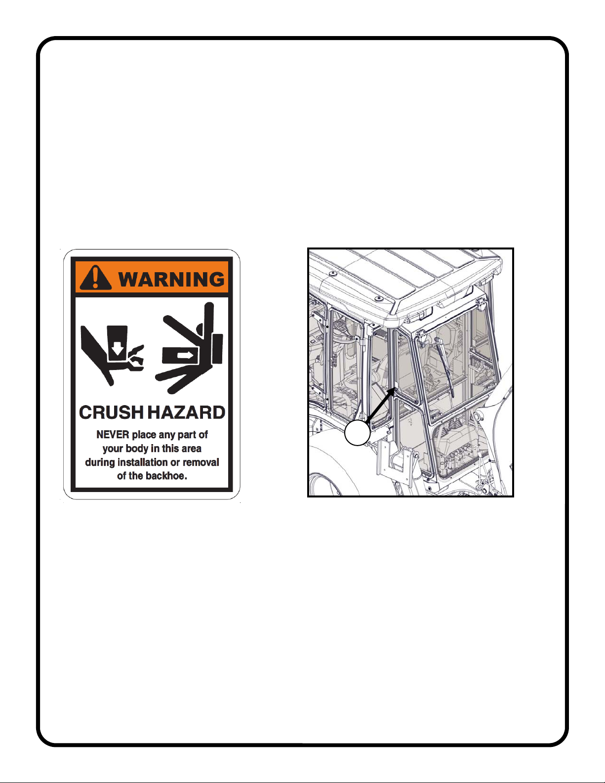
4.1 Remove and retain the outer most M12 nut, lock washer,
and flat washer from the upper front ROPS, just under the
canopy (see Figure 4.1). Push the end of the bolt flush
with the OEM side frame bracket, but do not remove.
Repeat for the other side.
4.2 With assistance, place the rear panel against the ROPS
per Figure 4.1 and push the M12 ROPS bolts through the
holes in the rear panel. Secure with the flat washer, lock
washer, and M12 nut removed in step 4.1. Leave loose.
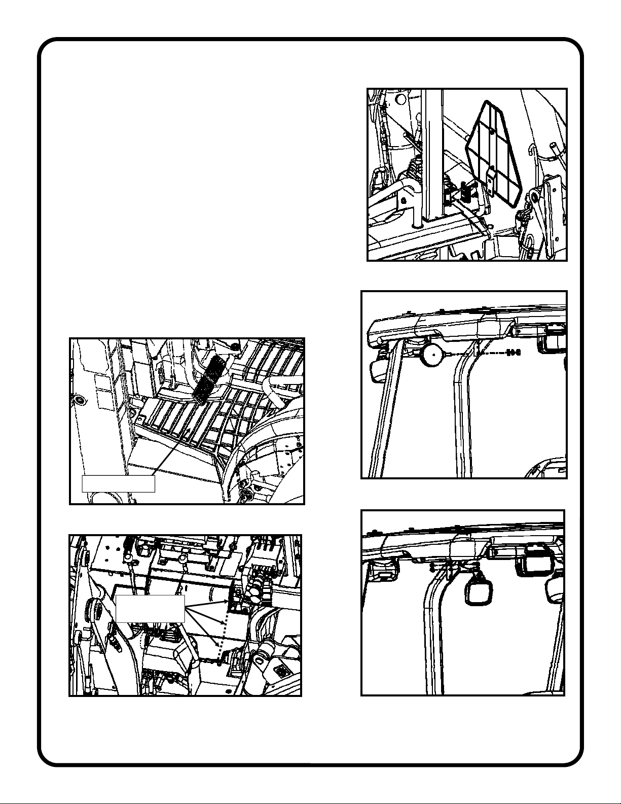
4.3 Remove the bulb rubber trim on the right side of the rear
panel to expose the u-shaped slot.
4.4 Slice the supplied rubber grommet and install around the
vehicle wire harness
4.5 Install the grommet into the slot and re-install the bulb
rubber trim from step 4.3. The grommet will deform when
the rubber is re-installed.
STEP 5: Left Side Frame
5.1 Set a ROPS clamp in place on the left side ROPS tube
with the larger flange towards the rear as shown in Figure
5.1.
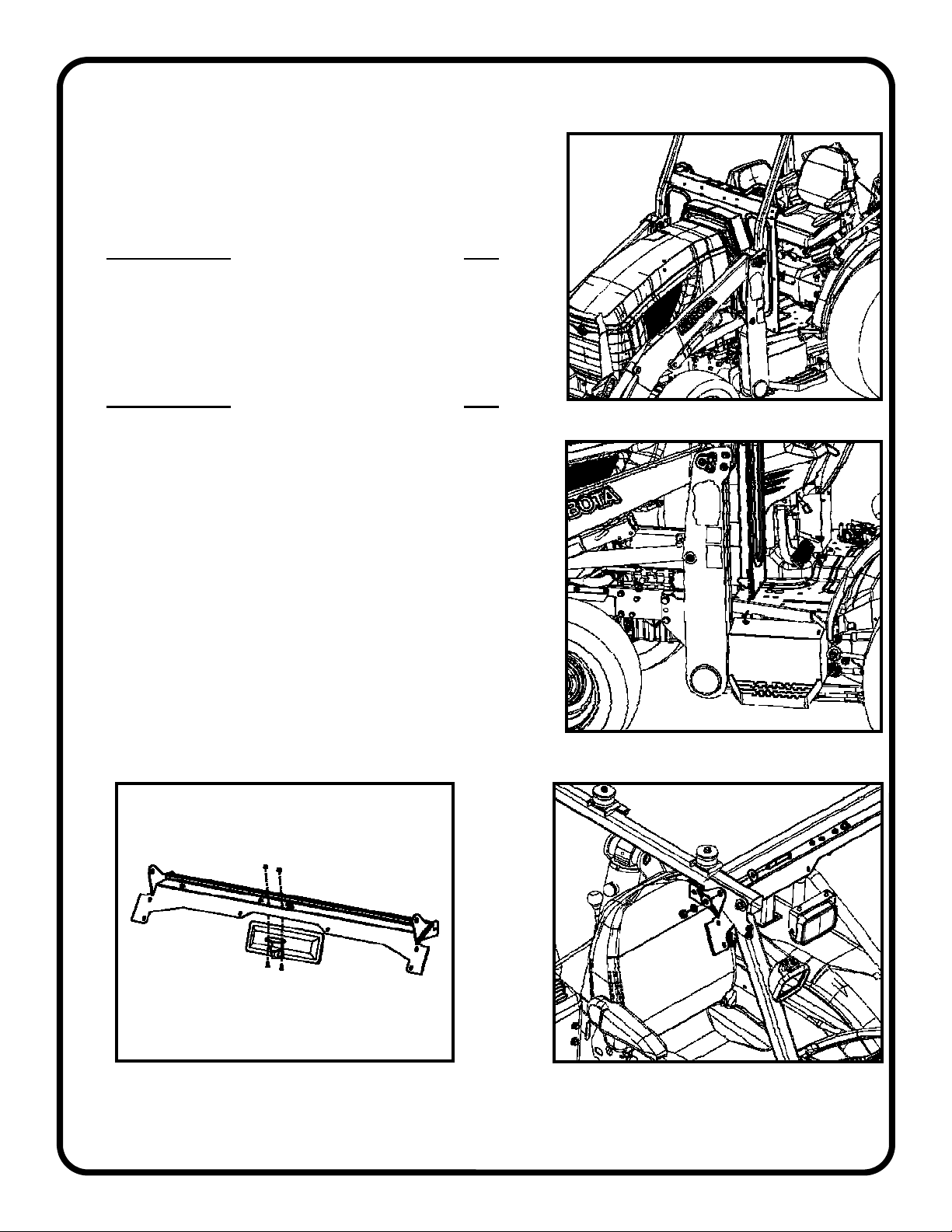
5.2 Disconnect the gas shock at the top of the door and
remove the door with assistance by unlatching at the front
via the outer handle button or inside lever, and lift the door
off the hinge pins. Remove the rear window by opening the
latch, squeezing the buttons to release the latch and lifting
the window off the hinge pins.
CAUTION: Be wary of the brass washer at each hinge pin.
For best results, remove the washers and set them aside
until the windows and doors are re-installed later.
Figure 4.1: Fasten Rear Panel
Figure 5.1: ROPS Clamp Set In Place
INSTALLATION
Figure 4.3: Install Grommet on Harness
Grommet
Bulb Rubber
ROPS Clamp

10 of 37
Figure 5.3: Side Frame to W/S Support Bolts
3/4” Long Screws
Flanged Nuts
Figure 5.4: Upper Rear Mount
STEP 5: Left Side Frame Cont.
5.3 With assistance, set the left side frame up under the roof
and onto the floor board and fasten the side frame to the
windshield support (see Figure 5.3). Use the top hole on
the front part of the windshield support, as the lower hole
will be used with the windshield itself. Leave hardware
loose.
Hardware Used QTY
5/16-18 x 3/4 Hex Head Flanged Cap Screw 2
5/16-18 Flanged Nylon Lock Nut 2
5.4 Install left upper rear mount (see Figure 5.4. Frame and
rear panel are hidden). Leave hardware loose.
Hardware Used QTY
5/16-18 x 3/4 Hex Head Flanged Cap Screw 2
INSTALLATION

11 of 37
STEP 5: Left Side Frame Cont.
5.5 Install two 1” long bolts and two nuts through the rear
panel, upper rear mount, and sideframe. (see Figure 5.5)
Leave hardware loose.
Hardware Used QTY
5/16-18 x 1 Hex Head Flanged Cap Screw 2
5/16-18 Flanged Nylon Lock Nut 2
5.6 Install a 3/4” long bolt and nut at the bottom of the rear
panel. Install in the uppermost hole. (see Figure 5.5)
Leave hardware loose.
Hardware Used QTY
5/16-18 x 3/4 Hex Head Flanged Cap Screw 1
5/16-18 Flanged Nylon Lock Nut 1
5.7 Fasten the side frame to the floor board (see Figure 5.7).
Leave hardware loose.
Hardware Used QTY
5/16-18 x 3/4 Button Head Socket Cap Screw 3
5/16-18 Flanged Nylon Lock Nut 3
5.8 Fasten the ROPS clamp to the side frame (see Fig. 5.8).
Leave hardware loose.
Hardware Used QTY
5/16-18 x 1 Hex Head Flanged Cap Screw 2
5.9 Fasten the side frame to the cowl (see Figure 5.9). Leave
hardware loose.
Hardware Used QTY
5/16-18 x 3/4 Hex Head Flanged Cap Screw 5
5/16-18 Flanged Nylon Lock Nut 5
Figure 5.5: Side Frame to Rear Panel Bolts
Figure 5.7: Side Frame to Floor Board Bolts
Figure 5.8: Side Frame ROPS Clamp
1” Screws
3/4” Screw Nut
Nuts
Button Head Screws
Flanged Nuts
Figure 5.9: Side Frame to Cowl Bolts
INSTALLATION

12 of 37
STEP 6: Right Side Frame
6.1 Disconnect the gas shock at the top of the right door and
remove the door with assistance by unlatching at the
front via the outer handle button or inside lever, and lift
the door off the hinge pins. Remove the rear window by
opening the latch, squeezing the buttons to release the
latch and lifting the window off the hinge pins.
CAUTION: Be wary of the brass washer at each hinge
pin. For best results, remove the washers and set them
aside until the windows and doors are re-installed later.
6.2 With assistance, set the side frame up under the roof
and onto the floor board and fasten the side frame to the
windshield support (see Figure 6.2). Use the top hole on
the front part of the windshield support, as the lower hole
will be used with the windshield itself. Leave hardware
loose.
Hardware Used QTY
5/16-18 x 3/4 Hex Head Flanged Cap Screw 1
5/16-18 Flanged Nylon Lock Nut 1
6.3 Install the upper rear mount opposite the one installed in
step 5.4.
Hardware Used QTY
5/16-18 x 3/4 Hex Head Flanged Cap Screw 2
6.4 Install two 1” long bolts and two nuts through the rear
panel, upper mount, and sideframe. (see Figure 6.4).
On the lower section of the rear panel, fasten the 3/4”
long bolts and nuts, with the lower most bolt mirroring
what was done on the left side frame. Leave hardware
loose.
Hardware Used QTY
5/16-18 x 3/4 Hex Head Flanged Cap Screw 2
5/16-18 x 1 Hex Head Flanged Cap Screw 2
5/16-18 Flanged Nylon Lock Nut 4
6.5 Fasten the side frame to the floor board (see Figure 6.5).
Leave hardware loose.
Hardware Used QTY
5/16-18 x 3/4 Button Head Socket Cap Screw 3
5/16-18 Flanged Nylon Lock Nut 3
Figure 6.4: Side Frame to Rear Panel Bolts
1” Long Screws Flanged Nuts
3/4” Long Screws
Figure 6.2: Side Frame to W/S Support Bolts
3/4” Long Screw
Flanged Nut
Figure 6.5: Side Frame to Floor Board Bolts
Button Head Screws
Flanged Nuts
INSTALLATION

13 of 37
STEP 6: Right Side Frame Cont.
6.6 Fasten the ROPS clamp to the side frame (see Fig. 6.6).
Leave hardware loose.
Hardware Used QTY
5/16-18 x 1 Hex Head Flanged Cap Screw 2
6.7 Fasten the side frame to the side of the cowl (see Figure
6.7). Leave hardware loose.
Hardware Used QTY
5/16-18 x 3/4 Hex Head Flanged Cap Screw 5
6.8 Fasten the side frame to the front of the cowl (see Fig.
6.8). Leave hardware loose.
Hardware Used QTY
5/16-18 x 3/4 Hex Head Flanged Cap Screw 2
5/16-18 Flanged Nylon Lock Nut 2
6.9 Fasten the side frame to the cowl junction box (see Figure
6.9). Leave hardware loose.
Hardware Used QTY
1/4-20 x 3/4 Button Head Socket Cap Screw 3
6.10 Connect the side frame wiring harness to the front wiper
harness on the windshield support.
6.11 Route the washer hose through the p-clamps on the
windshield support and connect to the fitting at the center
of the windshield support. Use soap as a lubricant for
easiest installation onto the barb.
Figure 6.6: Side Frame ROPS Clamp
Figure 6.7: Side Frame to Cowl Bolts
Figure 6.8: Side Frame to Cowl Bolts
Figure 6.9: Side Frame Junction Block
INSTALLATION

14 of 37
STEP 7: Rear Corner Fillers
7.1 Remove the rearmost fender bolts (both left and right
sides) and save for reuse.
7.2 Install the left rear corner filler to the vehicle (see Figures
7.1 and 7.2). Tighten the two 1/4-20 screws and leave the
remaining hardware loose.
Hardware Used QTY
1/4-20 x 3/4 Hex Head Flanged Cap Screw 2
#10-32 x 3/4 Truss Head Machine Screw 1
#10-32 Flanged Nylon Lock Nut 1
Fender Bolt and Nut 1
Note: Right rear corner filler will not fit with the optional rear
remote hydraulics installed without modification. See the install
manual for the 1KTLBL47HYD kit.
7.3 Fasten the right rear corner filler to the vehicle (see
Figures 7.3a and 7.3b, right wheel hidden for clarity).
Tighten the two 1/4-20 screws and leave the remaining
hardware loose.
Hardware Used QTY
1/4-20 x 3/4 Hex Head Flanged Cap Screw 2
1/4-20 x 5/8 Hex Head Flanged Cap Screw 1
1/4-20 Flanged Nylon Lock Nut 1
Fender Bolt and Nut 1
Figure 7.1: Left Rear Corner Filler
Figure 7.2: Left Rear Corner Filler
Figure 7.3b: Right Rear Corner Filler Figure 7.3a: Right Rear Corner Filler
Fender Bolt and Nut
#10-32 Screw and Nut
1/4-20 Screw
1/4-20 Screw
Fender Bolt
and Nut
1/4-20 x 5/8 Screw
and Nut
1/4-20 x 3/4
Screw
1/4-20 x 3/4
Screw
INSTALLATION

15 of 37
STEP 8: Lower Rear Panel Brackets
8.1 Remove the bottom M14 bolt from the side of the ROPS
tube and save for re-use.
Note: Do not remove both bolts at the same time as the
ROPS may settle and is difficult to reposition.
8.2 Fasten the left lower rear panel bracket to the vehicle using
the OEM bolt and sandwich a washer between the bracket
and the ROPS (see Figure 8.1, wheel and backhoe hidden
for clarity). Leave hardware loose.
Hardware Used QTY
9/16 x 1-3/8 Flat Washer 2
8.3 Remove the upper M14 bolt from the side of the ROPS
tube and re-fasten through the remaining hole in the
bracket. A 9/16 ID washer should be sandwiched between
the bracket and the ROPS. Note: Tape may be used to aid
in installation of the washer.
Hardware Used QTY
5/16-18 x 3/4 Hex Head Flanged Cap Screw 4
8.4 Repeat steps 8.1 through 8.3 on right hand side.
STEP 9: Heater Duct
9.1 Fasten the rear of the heater duct to the rear panel (see
Figure 9.1). Leave hardware loose.
Hardware Used QTY
5/16-18 x 3/4 Hex Head Cap Screw 2
9.2 Fasten the front of the heater duct to the cowl (see Figure
9.2). Leave hardware loose.
Hardware Used QTY
5/16-18 x 3/4 Hex Head Cap Screw 2
9.3 Fasten the corner of the heater duct to sideframe (see
Figure 9.3). Leave hardware loose.
Hardware Used QTY
5/16-18 x 3/4 Hex Head Cap Screw 1
5/16-18 Flanged Nylon Lock Nut 1
Figure 8.1: Left Lower Rear Panel Bracket
Figure 9.1: Heater Duct Rear Bolts
Figure 9.2: Heater Duct
5/16-18 Screws
Figure 9.3: Side Frame Bolt
3/4” Long Screw
Flanged Nut
3/4” Long Screws
INSTALLATION
OEM M14 Screws
and 9/16 Washers

16 of 37
STEP 10: Tighten all bolts
10.1 Torque all 5/16-18 bolts to 19 ft-lbs. (25.8 N-m) in the
following order:
1) Qty 3: windshield support to side frames.
2) Qty 4: ROPS brackets to side frames.
3) Qty 6: cab floorboards to tractor floor pan.
4) Qty 4: upper rear mounts to ROPS.
5) Qty 7: rear panel to upper rear mounts and sideframes.
6) Qty 12: cowl to side frames.
7) Qty 5: heater duct to cowl, rear panel, sideframe
8) Qty 2: cowl to tractor floor pan
9) Qty 2: tractor fender bolts (1L and 1R)
10) Qty 4: lower rear panel brackets (2L and 2R)
10.2 Torque (3) 1/4-20 bolts from the junction block to the right
side frame to 10 ft-lbs. (13.5 N-m).
10.3 Torque the (2) M12 ROPS bolts and nuts at the
windshield support to 62 ft-lbs. (84 N-m).
10.4 Torque the (2) M12 ROPS bolts and nuts at the top of the
rear panel to 62 ft-lbs. (84 N-m).
10.5 Torque the (4) M14 ROPS bolts for the lower rear panel
brackets to 87 ft-lbs. (118 N-m).
STEP 11: Windshield
11.1 Place the windshield onto the front of the side frames and
secure it with (10) 1/4-20 x 1-1/2” flanged hex bolts and
fender washers outside, and flanged nuts inside. Tighten
until there are no visible gaps between the windshield
rubber and frame (see Figure 11.1, roof hidden for clarity).
Hardware Used QTY
1/4-20 x 1-1/2 Hex Head Flanged Cap Screw 10
1/4 Fender Washer 10 Figure 12.1: Trim Floor Mat to Fit
Figure 11.1: Windshield
1/4-20 Flanged Nylon Lock Nut 6
STEP 12: Floor Mat
12.1 Re-install floor mat and trim to fit. Three alignment nubs on each side will have to be cut off where the
three button head bolts secure the side frames to the floor board. The front corners will also need to
be trimmed to fit around the cowl. (See Figure 12.1)
STEP 13: Electrical Harness Install
13.1 Locate the supplied power wire harness. Modify the harness to move the purple wire over to the ring
terminal end of the harness. Connect ring terminal on the red wire to the positive (+) battery terminal.
13.2 Connect ring terminal on the black wire to the negative (-) battery terminal.
13.3 Locate the tractor ignition source on the main harness just inside the battery. The connector is a
female bullet terminal wrapped in blue electrical tape.
13.4 Connect the male bullet terminal on the purple wire on the harness to the tractor ignition source.
13.5 Route the cab connector end of the wire harness under the floor of the tractor to the front of the right
sideframe and connect to the wire extending from the right frame.
13.6 Turn the ignition to on and check to see that the switches illuminate and the fan functions.
13.7 Secure the harness to the tractor using supplied cable ties.
13.8 Replace the battery cover.
INSTALLATION

17 of 37
STEP 14: Windshield Wiper
14.1 Remove the large hex nut, plastic washer, and rubber washer from the motor shaft making sure to
leave the black plastic standoff on the motor shaft. Put the large white nylon bushing with the collar
over the shaft as shown in Fig.14.1.
14.2 From the inside, insert the motor shaft out through the larger hole in the windshield until the white
nylon bushing is against the windshield. Replace the rubber washer, plastic washer, and hex nut on
the outside end of the shaft. Do not tighten completely at this point. CAUTION: Make sure that the
metal parts of the wiper motor do not contact the glass during installation. Damage could
occur.
14.3 From the inside, put the small white nylon bushing with the collar into the small hole in the
windshield and pivot the wiper motor so that the small hole aligns with the hole in the bushing. Insert
the 1/4-20 bolt through the internal tooth washer, the hole in the wiper motor bracket, the small
bushing, and finally the windshield. Next install the rubber washer, plastic washer, and cap nut.
14.4 Tighten the bolts at this time. Tighten the hex nut on the motor shaft to 30 inch-lbs and the 1/4-20
hex head bolt to 75 inch-lbs. WARNING: Over tightening wiper mounting hardware can damage
windshield and components.
14.5 Connect the wiper motor to the harness on the windshield support
NOTE: THE FOUR (4) ITEMS
MARKED * ARE PRE-
ASSEMBLED ON THE
WIPER SHAFT.
GLASS WINDSHIELD
*BLACK PLASTIC
STANDOFF
1/4” INTERNAL
TOOTH WASHER
1/4-20 x 5/8” HEX
HEAD BOLT
SMALL COLLARED
WHITE NYLON
BUSHING
RUBBER WASHER
PLASTIC WASHER
CAP NUT
LARGE COLLARED
WHITE NYLON
BUSHING
* RUBBER WASHER
* PLASTIC WASHER
* LARGE HEX NUT
FEMALE
ELECTRICAL
CONNECTOR
Figure 14.1: Wiper Motor Installation
INSTALLATION

18 of 37
STEP 15: Windshield Wiper Blade
15.1 Connect the windshield wiper blade and arm
together.
15.2 Lift the locking tab on the underside of the wiper
arm and extend the wiper arm to the desired
length. The angle of the blade can be adjusted by
loosening the small bolt on the top of the wiper
arm.
15.3 Press the wiper arm onto the shaft so that it is
positioned at the eight (8) o’clock position when
looked at from outside the cab. Turn the ignition
on and turn the wiper motor on and test its
operation. Adjust the arm sweep by turning the
blade, adjusting the arm length, or removing the
wiper arm off of the motor shaft and reinstalling it
at a different position.
15.4 Make sure wiper arm is fully seated on wiper
motor shaft so that the “L” shaped spring clip is
locked under the splines as seen in figure 15.4.
15.5 Once wiper is fully adjusted, tighten the set screw
on the wiper arm. The set screw location is noted
in illustration at location A
Note: a mirror was used in order to clearly see
and confirm the spring clip engagement. It may be
necessary to lightly tap the arm with a rubber
mallet to fully seat the arm.
CAUTION: to avoid breaking the windshield,
support the wiper motor with your hand when
tapping the arm. Wear safety glasses!
15.6 Connect the rubber hose on the wiper arm to the
fitting that is preinstalled on the windshield
support. It is recommended to use soap as a
lubricant for easiest installation onto the barb.
15.7 Push any additional wire or hose back into the
tube.
Figure 15.4: Wiper Arm Installation
Set
Screw
Spring
Clip
INSTALLATION

19 of 37
STEP 16: Rear Panel Windows
Note: if installing with the optional rear remote hydraulics, the
small lower right window will not be installed. See install
manual provided with 1KTLBL47HYD for more details.
16.1 Attach each of the three rear windows to the rear panel in
the same manner as the windshield (see Figure 16.1).
Use the 1-1/2” screws in the four corners where indicated
by the “A”
Hardware Used QTY
1/4-20 x 1-1/2 Hex Head Flanged Cap Screw 4
1/4-20 x 1-1/4 Hex Head Flanged Cap Screw 8
1/4 Fender Washer 12
1/4-20 Flanged Nylon Lock Nut 12
STEP 17: Doors and Windows
17.1 Apply grease to each of the four pins on each side frame
(a total of eight pins). Ensure that each pin has one brass
washer installed.
17.2 Hang each rear window onto the rear pins on each side
frame and connect the latch at the front of each window.
17.3 Hang each door onto the forward pins on each side frame.
Open the door to slightly and attach a gas shock onto the
ball studs on the door and frame, with the quick-release
end on the frame. (See Figures 17.3a and 17.3b)
Figure 16.1: Rear Panel Windows
Figure 17.3a: Right Door
Figure 17.3b: Left Door
INSTALLATION
A
A
A
A

20 of 37
STEP 18: Backhoe Cab
18.1 Fasten the backhoe cab footers to the backhoe floor
board sides (see Figure 18.1, outriggers hidden for
clarity). Place the 3/8 fender washer over the shoulder
screw, then sandwich the 5/16 fender washer between
the backhoe cab footers and the backhoe floor board
sides. The new footers should then be able to float a
little side to side. Tighten hardware.
Hardware Used QTY
3/8 x 1/4 Socket Head Shoulder Screw 4
3/8 x 1-1/4 Fender Washer 4
5/16 x 1 Fender Washer 4
5/16-18 Flanged Nylon Lock Nut 4
18.2 Attach the supplied velcro to the backhoe as shown in
Figure 18.2. Be sure to clean the surfaces properly
before installation. Note: the upper Velcro strip should
go on the inside of the black plastic cover along the
bottom edge of the plastic. The vinyl panel can be
used as a guide.
18.3 Attach another section of the supplied velcro to the
backhoe cab as shown in Figure 18.3.
18.4 With assistance, place the backhoe cab on to the
backhoe cab footers (see Figure 18.4, outriggers
hidden for clarity).
Figure 18.1: Backhoe Cab Footers
Figure 18.4: Drop On Backhoe Cab
INSTALLATION
Figure 18.2: Attach Velcro to Backhoe
Velcro on Inside
of plastic
Velcro on this
side of toe plates
Velcro
Figure 18.3: Attach Velcro to Backhoe Cab
This manual suits for next models
1
Table of contents
Other Curtis Farm Equipment manuals
Popular Farm Equipment manuals by other brands

Grifo
Grifo DVEP50I Instruction handbook

New Holland
New Holland Haybine 499 Operator's manual

KINZE Manufacturing, Inc.
KINZE Manufacturing, Inc. 3700 Operator's manual

Bridgeview
Bridgeview Bale King 6100 Operator's & parts manual

Te Pari
Te Pari Racewell HD3 Quick setup guide

Bee Home
Bee Home Bee Home Assembly & maintenance guide