Grizzly G9933 User manual

The following changes were recently made since the owner's manual was printed:
• (3) EMERGENCY STOP buttons have been added to machine cabinet.
• Magnetic switch parts have been updated to reflect change made in January, 2004.
• Spindle switch parts have been updated to reflect change made in March, 2006.
Aside from this information, all other content in the owner's manual applies and MUST be read and under-
stood for your own safety. IMPORTANT: Keep this update with the owner's manual for future reference.
READ THIS FIRST
For questions or help with this product contact Tech Support at (570) 546-9663 or techsupport@grizzly.com
Model G9933
***IMPORTANT UPDATE***
For Machines Mfd. Since 05/22
and Owner's Manual Revised 05/09
COPYRIGHT © MAY, 2022 BY GRIZZLY INDUSTRIAL, INC.
WARNING: NO PORTION OF THIS MANUAL MAY BE REPRODUCED IN ANY SHAPE
OR FORM WITHOUT THE WRITTEN APPROVAL OF GRIZZLY INDUSTRIAL, INC.
#CS22357 PRINTED IN TAIWAN
Revised Parts
101V2
164A
179-2V2
179-1V2
182V2
226V2
54
55
54-1
54-3
54-2
82
REF PART # DESCRIPTION REF PART # DESCRIPTION
54 P9933054 EMERGENCY STOP BUTTON ASSEMBLY 101V2 P9933101V2 CABINET FRAME V2.05.22
54-1 P9933054-1 STOP BUTTON KEYON KB2-BE102 164A P9933164A FWD/ REV SWI TCH V2. 03. 0 6
54-2 P9933054-2 BUTTON BASE 179-1V2 P9933179-1V2 OL RELAY NHD TH-12 12/18 V2.01.04
54-3 P9933054-3 TAP SCREW M4 X 42 179-2V2 P9933179-2V2 CONTACTOR NHD C-12D10 220V V2.01.04
55 P9933055 PHLP HD SCR M4-.7 X 8 182V2 P9933182V2 MAG SWITCH BOX NHD V2.01.04
82 P9933082 E-STOP BUTTON CORD 24G 2W 48" 226V2 P9933226V2 MAG SWITCH ASSY NHD V2.01.04

-2- G9933 Update (Mfd. Since 05/22)
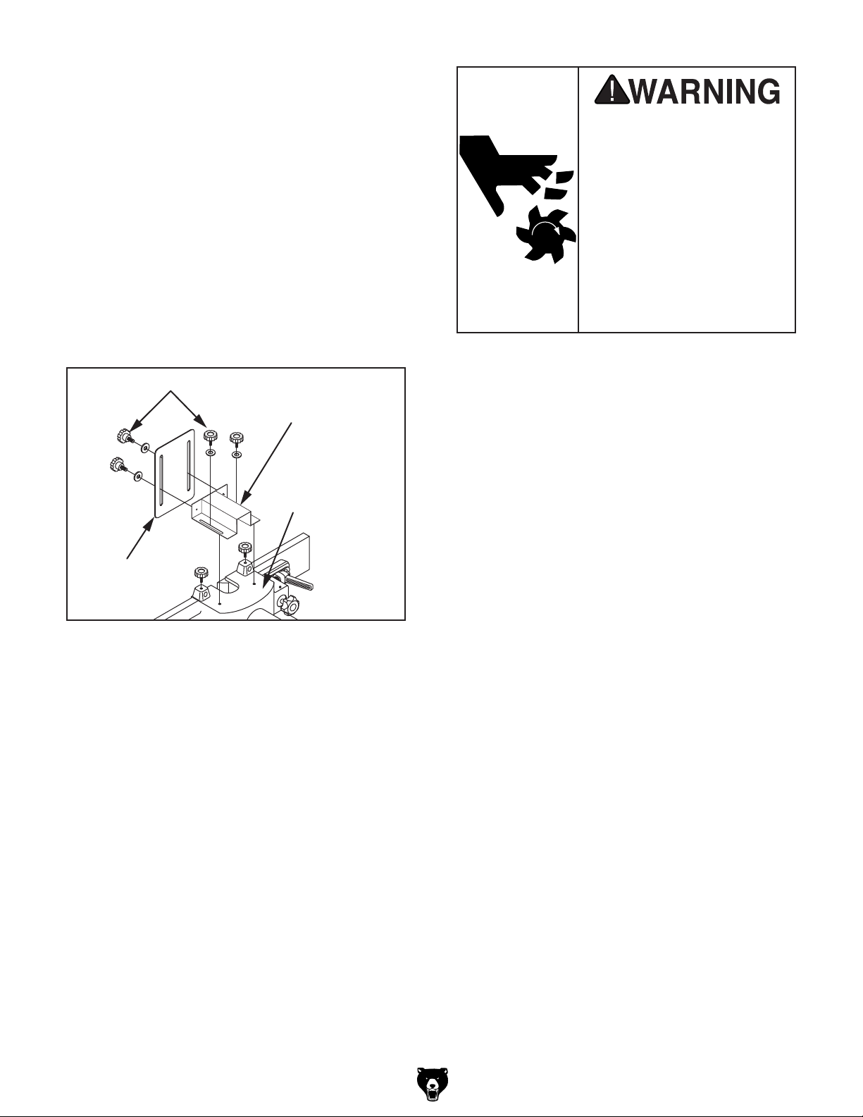
3. Secure the fence and guard assemblies to
the table with (6) M10-1.5 x 30 hex bolts and
10mm flat washers, as shown in Figure 1.
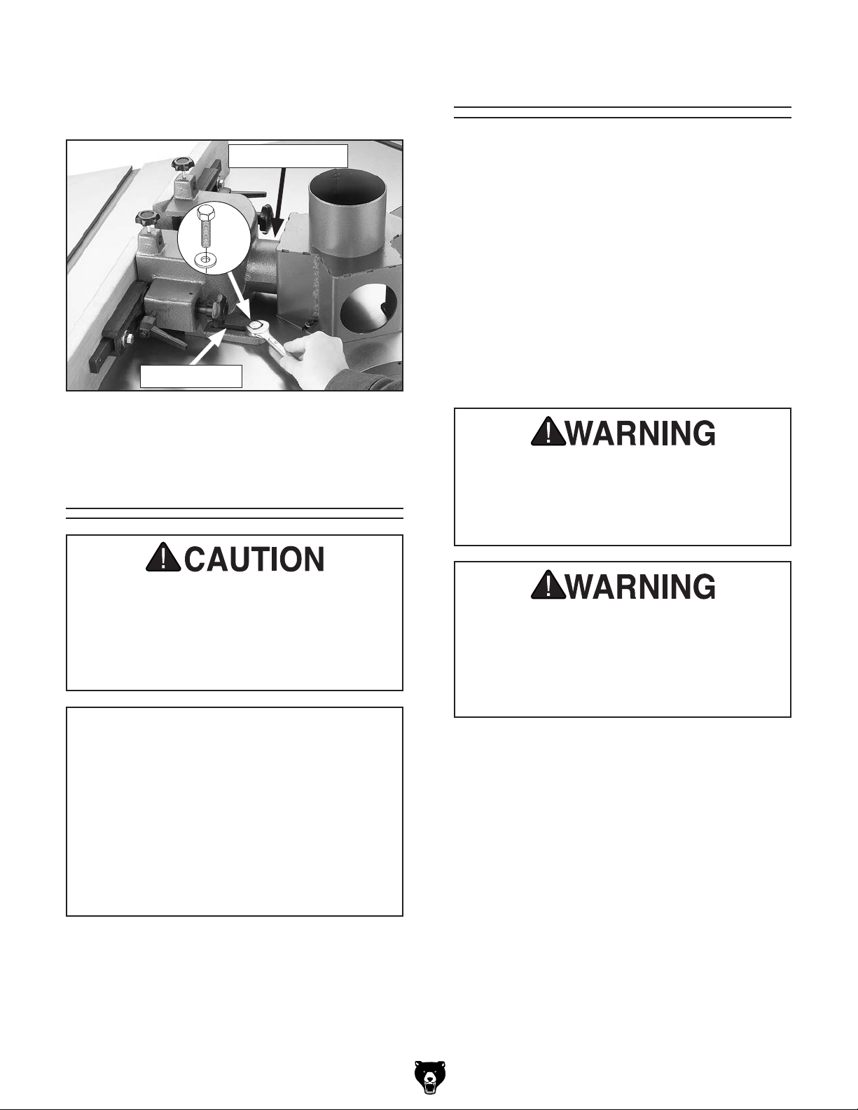
Connect an adequate dust collection system to
the 4" central dust hood. Make sure the dust
hose is supported in a vertical position above the
shaper table so that it is not in contact with any
other part of the shaper and will not interfere with
safe working conditions at each station.
Figure 1. Securing fence assembly and guard to
the table.
Guard Dust Port
x 6
Mounting Slot
Test Run
(Replaces Page 17 in Owner's Manual)
Dust Collection
Minimum CFM at Each Dust Port: 400 CFM
Do not confuse CFM recommendation with rat-
ing of dust collector. To determine CFM at dust
port, you must consider these variables: (1)
CFM rating of dust collector, (2) hose type and
length between dust collector and machine, (3)
number of branches or wyes, and (4) amount of
other open lines throughout system. Explaining
how to calculate these variables is beyond
scope of this manual. Consult expert or pur-
chase good dust collection "how-to" book.
This machine creates a lot of wood chips/
dust during operation. Breathing airborne
dust on a regular basis can result in perma-
nent respiratory illness. Reduce your risk
by wearing a respirator and capturing the
dust with a dust-collection system.
DO NOT start machine until all preceding
setup instructions have been performed.
Operating an improperly set up machine
may result in malfunction or unexpect-
ed results that can lead to serious injury,
death, or machine/property damage.
Serious injury or death can result from
using this machine BEFORE understanding
its controls and related safety information.
DO NOT operate, or allow others to operate,
machine until the information is understood.
To test run machine:
1. Clear all setup tools away from machine.
2. Press all EMERGENCY STOP buttons in.
3. Turn all spindle switches to OFF position.
4. Connect machine to power.
5. Twist EMERGENCY STOP buttons clockwise
until they spring out. This resets switches so
machine can start.
Once assembly is complete, test run the machine
to ensure it is properly connected to power and
safety components are functioning correctly.
If you find an unusual problem during the test run,
immediately stop the machine, disconnect it from
power, and fix the problem BEFORE operating the
machine again. The
Troubleshooting
table in the
SERVICE section of this manual can help.
The Test Run consists of verifying the following:
1) The motors power up and run correctly, and 2)
the EMERGENCY STOP button safety features
are functioning properly.

G9933 Update (Mfd. Since 05/22) -3-
6. Press ON button (see Figure 2). 8. Press EMERGENCY STOP button at station
#1 to turn motor OFF (see Figure 2).
9. WITHOUT resetting EMERGENCY STOP
button, try to start motor. Motor should not
start.
— If motor does not start, safety feature of
EMERGENCY STOP button is working
correctly. Proceed to Step 10.
— If motor does start, immediately turn it
OFF and disconnect power. Safety feature
of EMERGENCY STOP button is NOT
working properly and must be replaced
before further using machine.
10. Turn station spindle switch to OFF position.
11. Reset EMERGENCY STOP button at
station #1.
12. Repeat Steps 7–11 at station #2, then at sta-
tion #3.
13. Press OFF button.
7. At station #1, turn spindle switch to FOR posi-
tion to turn motor ON (see Figure 2). Motor
should run smoothly and without unusual
problems or noises.
— If spindle rotates in opposite direction
indicated by spindle switch, turn machine
OFF, disconnect power, then make sure
station motor and magnetic switch are
wired correctly (refer to wiring diagrams
beginning on Page 5 of this update).
Recommended
Adjustments
For your convenience, the adjustments listed
below have been performed at the factory and no
further setup is required to operate your machine.
However, because of the many variables involved
with shipping, we recommend that you at least
verify the following adjustments to ensure the best
possible results from your new machine.
Step-by-step instructions for these adjustments
can be found on the following referenced pages
in the owner's manual.
Factory adjustments that should be verified:
• V-belt tension (Page 38).
• Table insert adjustment (Page 41).
• Fence alignment (Page 42).
(Replaces Page 18 in Owner's Manual)
Station #1
Spindle Switch
Figure 2. Location of station #1 controls.
Station #1
EMERGENCY
STOP
Button
ON/OFF
Button
Machine is designed to
be used with only one
motor operating at a time.
Attempting to have more
than one operator using
this machine at the same
time may lead to an over-
load or cause serious per-
sonal injury due to unsafe
working conditions.

-4- G9933 Update (Mfd. Since 05/22)
SECTION 4: OPERATIONS
To reduce your risk of
serious injury, read this
entire manual BEFORE
using machine.
Keep hair, clothing, and
jewelry away from mov-
ing parts at all times.
Entanglement can result
in death, amputation, or
severe crushing injuries!
(Replaces Page 19 in Owner's Manual)
No list of safety guidelines can be com-
plete. Every shop environment is different.
Always consider safety first, as it applies to
individual working conditions. Use machin-
ery with caution/respect. Failure to do so
could result in serious personal injury,
damage to equipment, or poor work results.
Power Controls
Power ON/OFF Switch
There is one power ON/OFF switch for the entire
machine located on the cabinet (see Figure 3).
When this switch is turned ON, power flows to
each of the station spindle switches.
Spindle Switch
Figure 3. Power controls (station #1 shown).
EMERGENCY
STOP
Button
ON/OFF
Button
Spindle Switch
Each station of your shaper is equipped with an
independent spindle switch (see Figure 3) that
controls the spindle rotation. When there is power
flowing to the machine, the spindle switch is used
to select the direction of spindle rotation or to stop
the rotation.
To reduce risk of eye injury from flying
chips or lung damage from breathing dust,
always wear safety glasses and a respirator
when operating this machine.
EMERGENCY STOP Button
There is an EMERGENCY STOP button at each
station (see Figure 3) to stop all three spindles.
These buttons can be activated by a knee when
hands are full or when the ON/OFF switch or
spindle switches cannot be reached.
If you are inexperienced with this machine
type, WE STRONGLY RECOMMEND that
you seek training outside of this manual.
Read books/magazines or get formal train-
ing before beginning projects. Regardless
of content, Grizzly Industrial will not be held
liable for accidents due to lack of training.

-5-
READ ELECTRICAL SAFETY
ON PAGE 46 OF MANUAL!
G9933 Update (Mfd. Since 05/22)
Wiring Overview
Table
Top View
Incoming Power
Junction Box
220V Single-Phase
Power Source
Station #1
Station #2
Station #3
Station Rotary
Spindle Switch
Main ON/OFF
Switch
Station
Magnetic
Switch Station Motor
Symbol Key:
Station EMERGENCY
STOP Button
(Replaces Page 47 in Owner's Manual)

-6- READ ELECTRICAL SAFETY
ON PAGE 46 OF MANUAL!G9933 Update (Mfd. Since 05/22)
Wiring Diagram (A)
Top
Bottom
U6
RS
5V
98
96
U/2
V/4
1L15L3
13NO 3L2
W/6
2T1
6T3 4T2
14NO
95
A2 A1
12
15
18
Contactor
Overload
Relay
Spindle Switch
Power ON/OFF Switch
Station #1 Magnetic Switch
Station Motor
Ground
Hot
Hot
G
X
Y
220V L6-30 Plug
(As Recommended)
Incoming Power
Junction Box
Ground
Start Capacitor
400MFD 125VAC
To Station #2
Magnetic Switch
2
1NC
Station #1
EMERGENCY STOP
Button
KEYON
KB2-BE102
GND
2
1NC
Station #2
EMERGENCY STOP
Button
KEYON
KB2-BE102
2
1NC
Station #3
EMERGENCY STOP
Button
KEYON
KB2-BE102
R
R
YK600
NHD C-12D10
TH-12
KEDU ZH-HC-3
R
14
X2
22
X1
13 21
OFF
ON
(Replaces Page 48 in Owner's Manual)

-7-
READ ELECTRICAL SAFETY
ON PAGE 46 OF MANUAL!
G9933 Update (Mfd. Since 05/22)
Wiring Diagram (B)
98
96
U/2
V/4
1L15L3
13NO 3L2
W/6
2T1
6T3 4T2
14NO
95
A2 A1
12
15
18
Contactor
Overload
Relay
NHD C-12D10
TH-12
98
96
U/2
V/4
1L15L3
13NO 3L2
W/6
2T1
6T3 4T2
14NO
95
A2 A1
12
15
18
Contactor
Overload
Relay
NHD C-12D10
TH-12
Station #2 Magnetic Switch
To Station
Spindle Switch
& Motor
Station #3 Magnetic Switch
To Station
Spindle Switch
& Motor
From Station #1
Magnetic Switch
A1 A1
(Replaces Page 49 in Owner's Manual)


COPYRIGHT © MAY, 2017 BY GRIZZLY INDUSTRIAL, INC.
WARNING: NO PORTION OF THIS MANUAL MAY BE REPRODUCED IN ANY SHAPE
OR FORM WITHOUT THE WRITTEN APPROVAL OF GRIZZLY INDUSTRIAL, INC.
#BL18964 PRINTED IN TAIWAN
The following change was recently made to this machine since the owner's manual was printed:
• Added a front guard to each spindle guard assembly.
Aside from this information, all other content in the owner's manual applies and MUST be read and under-
stood for your own safety. IMPORTANT: Keep this update with the owner's manual for future reference.
READ THIS FIRST
For questions or help with this product contact Tech Support at (570) 546-9663 or techsupport@grizzly.com
Model G9933
***IMPORTANT UPDATE***
For Machines Mfd. Since 12/16
and Owner's Manual Revised 05/09
236
235 234
233
301
New Parts
REF PART # DESCRIPTION
233 P9933233 FRONT GUARD EXTENSION PLATE
234 P9933234 FRONT GUARD
235 P9933235 FLAT WASHER 6MM
236 P9933236 KNOB BOLT M6-1 X 16 6-LOBE
301 P9933301 CUTTER HAZARD LABEL
New Inventory
Inventory Qty
A. Front Guards .............................................. 3
B. Front Guard Extension Plates .................... 3
C. Flat Washers 6mm ................................... 12
D. Knob Bolts M6-1 x 16 ............................... 12
A
B
C D
Note: The inventory items above are pre-installed
on the fence and guard assemblies. Refer to the
Assembly section in the owner's manual for
instructions on assembling the fence and guard
assemblies.

-2- G9933 Update (Mfd. Since 12/16)
Front Guard Positioning
The front guard helps protect the user from addi-
tional exposure to the cutter and any chips thrown
by it. To minimize the risk of injury, the front guard
must be adjusted so it encloses as much of the
spindle area as possible, while still allowing the
workpiece to pass through the cut. Typically this
means the front guard is positioned to just clear
the top of the workpiece.
To position the front guard (see Figure 44), loosen
the top knob bolts and slide the extension plate in
or out, then loosen the front knob bolts and raise
or lower the front guard as needed. Tighten the
knob bolts to secure the setting.
All guards MUST be
installed on your shaper
before operating it.
Shapers can quickly cause
serious injury if some kind
of guard is not used. To
reduce your risk of injury,
read and follow the entire
Owner's Manual carefully
and do additional research
on shop-made guards and
safety jigs.
Figure 44. Extension plate and front guard
attached to spindle guard.
Knob Bolts
Extension Plate
Front
Guard
Spindle Guard

MODEL G9933
THREE SPINDLE SHAPER
OWNER'S MANUAL
8DENG><=I?6CJ6GN!'%%'7N<G>OOAN>C9JHIG>6A!>C8#!G:K>H:9B6N!'%%.IH
WARNING: NO PORTION OF THIS MANUAL MAY BE REPRODUCED IN ANY SHAPE
OR FORM WITHOUT THE WRITTEN APPROVAL OF GRIZZLY INDUSTRIAL, INC.
;DGB68=>C:HB6CJ;68IJG:9H>C8:&$%'IG(**'EG>CI:9>CI6>L6C

4HISMANUALPROVIDESCRITICALSAFETYINSTRUCTIONSONTHEPROPERSETUP
OPERATIONMAINTENANCEANDSERVICEOFTHISMACHINEEQUIPMENT
&AILURETOREADUNDERSTANDANDFOLLOWTHEINSTRUCTIONSGIVENINTHIS
MANUALMAYRESULTINSERIOUSPERSONALINJURYINCLUDINGAMPUTATION
ELECTROCUTIONORDEATH
4HEOWNEROFTHISMACHINEEQUIPMENTISSOLELYRESPONSIBLEFORITS
SAFEUSE4HISRESPONSIBILITYINCLUDESBUTISNOTLIMITEDTOPROPER
INSTALLATIONINASAFEENVIRONMENTPERSONNELTRAININGANDUSAGE
AUTHORIZATIONPROPERINSPECTIONANDMAINTENANCEMANUALAVAILABILITY
ANDCOMPREHENSIONAPPLICATIONOFSAFETYDEVICESBLADECUTTERINTEG
RITYANDTHEUSAGEOFPERSONALPROTECTIVEEQUIPMENT
4HEMANUFACTURERWILLNOTBEHELDLIABLEFORINJURYORPROPERTYDAMAGE
FROMNEGLIGENCEIMPROPERTRAININGMACHINEMODIFICATIONSORMISUSE
3OMEDUSTCREATEDBYPOWERSANDINGSAWINGGRINDINGDRILLINGAND
OTHERCONSTRUCTIONACTIVITIESCONTAINSCHEMICALSKNOWNTOTHE3TATE
OF#ALIFORNIATOCAUSECANCERBIRTHDEFECTSOROTHERREPRODUCTIVE
HARM3OMEEXAMPLESOFTHESECHEMICALSARE
s ,EADFROMLEADBASEDPAINTS
s #RYSTALLINESILICAFROMBRICKSCEMENTANDOTHERMASONRYPRODUCTS
s !RSENICANDCHROMIUMFROMCHEMICALLYTREATEDLUMBER
9OURRISKFROMTHESEEXPOSURESVARIESDEPENDINGONHOWOFTENYOU
DOTHISTYPEOFWORK4OREDUCEYOUREXPOSURETOTHESECHEMICALS
7ORKINAWELLVENTILATEDAREAANDWORKWITHAPPROVEDSAFETYEQUIP
MENTSUCHASTHOSEDUSTMASKSTHATARESPECIALLYDESIGNEDTOFILTER
OUTMICROSCOPICPARTICLES

Table of Contents
SECTION 5: ACCESSORIES......................... 34
SECTION 6: MAINTENANCE......................... 36
HX]ZYjaZ###################################################### (+
8aZVc^c\EgdiZXi^c\################################## (+
AjWg^XVi^dc################################################### (,
K"7ZaiIZch^dc^c\GZeaVXZbZci############### (-
SECTION 7: SERVICE ................................... 39
IgdjWaZh]ddi^c\########################################### (.
IVWaZ>chZgi6Y_jhibZci############################### )&
He^cYaZGZeaVXZbZci################################### )&
6a^\c^c\;ZcXZ############################################# )'
He^cYaZ8Vgig^Y\Z$7ZVg^c\GZeaVXZbZci##### )(
SECTION 8: WIRING...................................... 46
L^g^c\HV[Zin>chigjXi^dch############################ )+
L^g^c\DkZgk^Zl########################################### ),
L^g^c\9^V\gVb6###################################### )-
L^g^c\9^V\gVb7###################################### ).
SECTION 9: PARTS....................................... 50
BdidgHe^cYaZ########################################### *%
8VW^cZiIVWaZ########################################### *'
;ZcXZ<jVgY6hhZbWan############################ *(
AVWZaEaVXZbZci########################################## *)
WARRANTY AND RETURNS ........................ 57
INTRODUCTION............................................... 2
BVcjVa6XXjgVXn########################################### '
8dciVXi>c[d####################################################'
BVX]^cZ9ZhXg^ei^dc###################################### '
>YZci^[^XVi^dc################################################### (
BVX]^cZ9ViVH]ZZi###################################### )
SECTION 1: SAFETY....................................... 6
HV[Zin>chigjXi^dch[dgBVX]^cZgn################## +
6YY^i^dcVaHV[Zin>chigjXi^dch[dgH]VeZgh##### -
SECTION 2: CIRCUIT REQUIREMENTS ........ 9
''%KH^c\aZ"E]VhZDeZgVi^dc####################### .
EdlZg8dccZXi^dc######################################## &%
SECTION 3: SETUP ....................................... 11
CZZYZY[dgHZije######################################### &&
JceVX`^c\#################################################### &&
>ckZcidgn######################################################&'
8aZVcje######################################################## &(
H^iZ8dch^YZgVi^dch###################################### &)
A^[i^c\EaVX^c\H]VeZg############################## &*
Bdjci^c\idH]de;addg############################### &*
6hhZbWan##################################################### &+
9jhi8daaZXi^dc############################################# &,
IZhiGjc###################################################### &,
GZXdbbZcYZY6Y_jhibZcih######################## &-
SECTION 4: OPERATIONS ........................... 19
EdlZg8dcigdah############################################ &.
DeZgVi^dcDkZgk^Zl##################################### '%
HidX`>cheZXi^dcGZfj^gZbZcih################ '%
8jiiZgGdiVi^dc9^gZXi^dc############################# '&
8jiiZg=Z^\]i################################################ '&
=daY"9dlch################################################# ''
;ZcXZ6Y_jhibZci######################################## ''
8]Vc\^c\HeZZYh######################################## '(
IVWaZ>chZgih################################################ '*
8jiiZg>chiVaaVi^dc######################################### '*
8jiiZgHV[Zin<jVgY##################################### ',
:Y\Z8jii^c\################################################ '-
8jii^c\GVWWZih########################################### '.
H]Ve^c\HbVaaHidX`#################################### (%
GjW8daaVgh################################################## (&
>ggZ\jaVgH]Ve^c\######################################### ('
EViiZgcLdg`################################################ ('

"'" BdYZa<..((B[\&$%'
INTRODUCTION
LZhiVcYWZ]^cYdjgbVX]^cZh#>[ndj]VkZVcn
hZgk^XZfjZhi^dch!eVgihgZfjZhihdg\ZcZgVafjZh"
i^dchVWdjii]ZbVX]^cZ!eaZVhZXVaadglg^iZjhVi
i]ZadXVi^dca^hiZYWZadl#
<g^ooan>cYjhig^Va!>cX#
&'%(AnXdb^c\BVaa8^gXaZ
BjcXn!E6&,,*+
E]dcZ/*,%*)+".++(
;Vm/-%%)(-"*.%&
:"BV^a/iZX]hjeedgi5\g^ooan#Xdb
>[ndj]VkZVcnXdbbZcihgZ\VgY^c\i]^hbVcjVa!
eaZVhZlg^iZidjhVii]ZVYYgZhhWZadl/
<g^ooan>cYjhig^Va!>cX#
8$DIZX]c^XVa9dXjbZciVi^dcBVcV\Zg
E#D#7dm'%+.
7Zaa^c\]Vb!L6.-'',"'%+.
:bV^a/bVcjVah5\g^ooan#Xdb
Contact Info
Machine Description
Manual Accuracy
LZVgZegdjYidd[[Zgi]^hbVcjVal^i]ndjgcZl
bVX]^cZ LZkZ bVYZ ZkZgn Z[[dgi id WZ ZmVXi
l^i]i]Z^chigjXi^dch!heZX^[^XVi^dch!YgVl^c\h!VcY
e]did\gVe]hd[i]ZbVX]^cZlZjhZYl]Zclg^i"
^c\ i]^h bVcjVa# =dlZkZg! hdbZi^bZh Zggdgh Yd
]VeeZcVcYlZVedad\^oZ[dgi]Zb#
6ahd!dl^c\iddjgeda^Xn d[Xdci^cjdjh^begdkZ"
bZci!your machine may not exactly match the
manual#>[ndj[^cYi]^hidWZi]ZXVhZ!VcYi]ZY^["
[ZgZcXZWZilZZci]ZbVcjVaVcYbVX]^cZaZVkZh
ndj ^c YdjWi! X]ZX` djg lZWh^iZ [dg i]Z aViZhi
bVcjVajeYViZdgXVaaiZX]c^XVahjeedgi[dg]Zae#
7Z[dgZXVaa^c\![^cYi]ZbVcj[VXijgZYViZd[ndjg
bVX]^cZWnadd`^c\Vii]ZYViZhiVbeZY^cidi]Z
bVX]^cZ >9 aVWZa hZZ WZadl# I]^h l^aa ]Zae jh
YZiZgb^cZ ^[ i]Z bVcjVa kZgh^dc ndj gZXZ^kZY
bViX]Zhi]ZbVcj[VXijgZYViZd[ndjgbVX]^cZ#
;dgndjgXdckZc^ZcXZ!lZedhiVaaVkV^aVWaZbVc"
jVahVcYbVcjVajeYViZh[dg[gZZdcdjglZWh^iZ
Viwww.grizzly.com#6cnjeYViZhidndjgbdYZa
d[ bVX]^cZ l^aa WZ gZ[aZXiZY ^c i]ZhZ YdXjbZcih
VhhddcVhi]ZnVgZXdbeaZiZ#
BVcj[VXijgZ9ViZ
d[NdjgBVX]^cZ I]Z h]VeZg ^h V kZghVi^aZ lddYldg`^c\ bVX]^cZ
jhZYidbV`ZXdcidjgZYXjihdci]ZZY\Zd[i]Z
ldg`e^ZXZ# I]^h ^h VXXdbea^h]ZY Wn eVhh^c\ i]Z
hidX`Vadc\i]Z[ZcXZVcYeVhii]Zhe^cc^c\Xji"
iZg#
8jiiZgh VgZ VkV^aVWaZ ^c bVcn Y^[[ZgZci egd[^aZh
[dgVl^YZkVg^Zind[Xjii^c\Veea^XVi^dch!hjX]Vh
XVW^cZih! Yddgh! bdjaY^c\! XjgkZY e^ZXZh! VcY
[gZZ]VcYdgeViiZgcXjii^c\#
I]ZBdYZa<..((^hVi]gZZ"hiVi^dch]VeZgi]Vi^h
ine^XVaanjhZY^cVegdYjXi^dch]deWZXVjhZi]gZZ
Y^[[ZgZciXjiiZghXVcWZbdjciZYVcYVkV^aVWaZ[dg
jhZVii]ZhVbZi^bZ#

BdYZa<..((B[\&$%' "("
Identification
NOTICE
If you have never used this type of machine or equipment before, WE STRONGLY RECOMMEND
that you read books, review industry trade magazines, or get formal training before beginning
any projects. Regardless of the content in this section, Grizzly Industrial will not be held liable
for accidents caused by lack of training.
Figure 1.BdYZa<..((^YZci^[^XVi^dc#
Bdidg6XXZhh9ddg
He^cYaZ
Hl^iX]
B^iZg
<Vj\Z
;ZcXZ
9jhi=ddYEdgi
8jiiZg<jVgY =daY"9dlc
=Z^\]i
=VcYl]ZZa
AdX`

")" BdYZa<..((B[\&$%'
MACHINE DATA
SHEET
Customer Service #: (570) 546-9663 · To Order Call: (800) 523-4777 · Fax #: (800) 438-5901
MODEL G9933 THREE SPINDLE SHAPER
Product Dimensions:
Weight............................................................................................................................................................ 1185 lbs.
Length/Width/Height.................................................................................................................45-1/2 x 52-1/8 x 45 in.
Foot Print (Length/Width)................................................................................................................. 37-1/4 x 34-1/4 in.
Shipping Dimensions:
Type........................................................................................................................................................... Wood Crate
Content............................................................................................................................................................ Machine
Weight............................................................................................................................................................ 1260 lbs.
Length/Width/Height............................................................................................................................. 50 x 54 x 43 in.
Electrical:
Switch........................................................................................................ Magnetic with Thermal Overload Protector
Switch Voltage...................................................................................................................................................... 220V
Minimum Circuit Size........................................................................................................................................ 30 amp
Plug Included............................................................................................................................................................No
Motors:
Main
Type.................................................................................................................. TEFC Capacitor Start Induction
Horsepower.................................................................................................................................................3 HP
Voltage........................................................................................................................................................220V
Prewired......................................................................................................................................................220V
Phase........................................................................................................................................................ Single
Amps.............................................................................................................................................................18A
Speed.................................................................................................................................................3450 RPM
Cycle..........................................................................................................................................................60 Hz
Number Of Speeds........................................................................................................................................... 1
Power Transfer ................................................................................................................................... Belt Drive
Bearings....................................................................................................................... Shielded and Lubricated
Main Specifications:
Operation Info
Max. Cutter Height............................................................................................................................... 4-9/16 in.
Max. Cutter Dia............................................................................................................................................ 6 in.
Spindle Sizes......................................................................................................................................... 1-1/4 in.
Spindle Lengths..................................................................................................................................... 5-7/8 in.
Exposed Spindle Length.............................................................................................................................. 4 in.
Spindle Cap Under The Nut................................................................................................................... 4-1/2 in.
Spindle Speeds...................................................................................................................... 7000, 10000 RPM
Spindle Travel.............................................................................................................................................. 4 in.
Spindle Openings.............................................................................................................. 3-1/4, 6-1/4, 8-1/4 in.
Machine Data Sheet

BdYZa<..((B[\&$%' "*"
Table Info
No. Of Table Inserts.......................................................................................................................................... 2
Table Insert Sizes I.D...................................................................................................................3-1/8, 6-1/4 in.
Table Insert Sizes O.D...............................................................................................................7-1/4, 9-3/16 in.
Table Counterbore Diameter..................................................................................................................8-1/4 in.
Table Counterbore Depth..........................................................................................................................3/8 in.
Table Size Length................................................................................................................................ 28-1/4 in.
Table Size Width.................................................................................................................................. 21-3/4 in.
Table Size Thickness........................................................................................................................... 3-1/16 in.
Floor To Table Height.................................................................................................................................35 in.
Table Fence Length............................................................................................................................. 27-1/8 in.
Table Fence Width................................................................................................................................ 13/16 in.
Table Fence Height................................................................................................................................3-7/8 in.
Miter Gauge Info
Miter Angle.......................................................................................................................................90 - 30 deg.
Miter Gauge Slot Type...............................................................................................................................T-Slot
Miter Gauge Slot Width............................................................................................................................. 3/4 in.
Miter Gauge Slot Height............................................................................................................................ 7/8 in.
Construction
Table Const............................................................................................................................. Ground Cast Iron
Base Const............................................................................................................................. Pre-Formed Steel
Body Assembly Const.......................................................................................................................... Cast Iron
Cabinet Const......................................................................................................................... Pre-Formed Steel
Fence Const....................................................................................................................... Cast Iron with Wood
Miter Gauge Const............................................................................................................................... Cast Iron
Guard Const......................................................................................................................................... Cast Iron
Spindle Bearings............................................................................................................. Sealed and Lubricated
Paint.......................................................................................................................................................... Epoxy
Other
No. Of Dust Ports.............................................................................................................................................. 1
Dust Port Size.............................................................................................................................................. 4 in.
Other Specifications:
Country Of Origin ..............................................................................................................................................Taiwan
Warranty ............................................................................................................................................................ 1 Year
Serial Number Location .................................................................................................. ID Label on Front of Cabinet
Assembly Time ........................................................................................................................................... 60 minutes
Features:
3 Separate Motors
3 Micro Adjustable Fences
3 Magnetic Reversing Switches
Spindles Include Spacer and Nuts
Vertical Spindle Lock
Spindle Turning Lock
Heavy Duty Miter Gauge Included
Includes Service Wrenches and Tool Box
Router Bit Spindle Available as an Option
3/4" and 1/2" Spindles Available as an Option
Three 4" Dust Ports
Two Spindle Speeds-7,000 & 10,000 RPM

"+" BdYZa<..((B[\&$%'
Safety Instructions for Machinery
4. ALWAYS USE HEARING PROTECTION
WHEN OPERATING MACHINERY.
BVX]^cZgn cd^hZ XVc XVjhZ eZgbVcZci
]ZVg^c\adhh#
5. WEAR PROPER APPAREL. 9D CDI
lZVgaddhZXadi]^c\!\adkZh!cZX`i^Zh!g^c\h!
dg_ZlZagni]ViXVc XViX] ^cbdk^c\eVgih#
LZVg egdiZXi^kZ ]V^g XdkZg^c\ id XdciV^c
adc\]V^gVcYlZVgcdc"ha^e[ddilZVg#
6. NEVER OPERATE MACHINERY WHEN
TIRED OR UNDER THE INFLUENCE OF
DRUGS OR ALCOHOL. 7ZbZciVaanVaZgi
ViVaai^bZhl]Zcgjcc^c\bVX]^cZgn#
1. READ ENTIRE MANUAL BEFORE
STARTING. DeZgVi^c\ bVX]^cZ WZ[dgZ
gZVY^c\ i]Z bVcjVa \gZVian ^cXgZVhZh i]Z
g^h`d[^c_jgn#
2. ALWAYS USE ANSI APPROVED
SAFETY GLASSES WHEN OPERATING
MACHINERY. :kZgnYVn ZnZ\aVhhZh dcan
]VkZ ^beVXi gZh^hiVci aZchZh·i]Zn VgZ
CDIhV[Zin\aVhhZh#
3. ALWAYS WEAR A NIOSH APPROVED
RESPIRATOR WHEN OPERATING
MACHINERY THAT PRODUCES DUST.
BdhiineZhd[YjhilddY!bZiVa!ZiX#XVc
XVjhZhZkZgZgZhe^gVidgn^aacZhhZh#
For Your Own Safety, Read Instruction
Manual Before Operating this Machine
The purpose of safety symbols is to attract your attention to possible hazardous conditions. This
manual uses a series of symbols and signal words intended to convey the level of importance
of the safety messages. The progression of symbols is described below. Remember that safety
messages by themselves do not eliminate danger and are not a substitute for proper accident
prevention measures.
Indicates a potentially hazardous situation which, if not avoided,
MAY result in minor or moderate injury. It may also be used to alert
against unsafe practices.
Indicates a potentially hazardous situation which, if not avoided,
COULD result in death or serious injury.
Indicates an imminently hazardous situation which, if not avoided,
WILL result in death or serious injury.
This symbol is used to alert the user to useful information about
proper operation of the machine.
NOTICE
Safety Instructions for Machinery
SECTION 1: SAFETY

BdYZa<..((B[\&$%' ","
7. ONLY ALLOW TRAINED AND PROP-
ERLY SUPERVISED PERSONNEL TO
OPERATE MACHINERY. BV`Z hjgZ
deZgVi^dc^chigjXi^dchVgZhV[ZVcYXaZVgan
jcYZghiddY#
8. KEEP CHILDREN/VISITORS AWAY.
@ZZe Vaa X]^aYgZc VcY k^h^idgh VlVn [gdb
bVX]^cZgn# L]Zc bVX]^cZ ^h cdi ^c jhZ!
Y^hXdccZXi ^i [gdb edlZg! adX` ^i dji! dg
Y^hVWaZ i]Z hl^iX] id bV`Z ^i Y^[[^Xjai [dg
jcVji]dg^oZYeZdeaZidhiVgii]ZbVX]^cZ#
9. UNATTENDED OPERATION. AZVk^c\
bVX]^cZ jcViiZcYZY l]^aZ ^ih gjcc^c\
\gZVian^cXgZVhZhi]Zg^h`d[VcVXX^YZcidg
egdeZginYVbV\Z#IjgcbVX]^cZOFFVcY
VaadlVaabdk^c\eVgihidXdbZ id V Xdb"
eaZiZhideWZ[dgZlVa`^c\VlVn#
10. DO NOT USE IN DANGEROUS
ENVIRONMENTS. 9D CDI jhZ bVX]^c"
Zgn ^c YVbe! lZi adXVi^dch! dg l]ZgZ Vcn
[aVbbVWaZdgcdm^djh[jbZhbVnZm^hi#
11. KEEP WORK AREA CLEAN AND WELL
LIGHTED. 8ajiiZgVcYYVg`h]VYdlhbVn
XVjhZVXX^YZcih#
12. USE A GROUNDED POWER SUPPLY
RATED FOR THE MACHINE AMPERAGE.
<gdjcYZYXdgYhb^c^b^oZh]dX`]VoVgYh#
DeZgVi^c\bVX]^cZdcVc^cXdggZXih^oZd[
X^gXj^i^cXgZVhZhg^h`d[[^gZ#
13.
ALWAYS DISCONNECT FROM POWER
SOURCE BEFORE SERVICING
MACHINERY#BV`ZhjgZhl^iX]^h ^c
D;;
edh^i^dcWZ[dgZgZXdccZXi^c\#
14. MAINTAIN MACHINERY WITH CARE.
@ZZeWaVYZhh]VgeVcYXaZVc[dgWZhiVcY
hV[ZhieZg[dgbVcXZ#;daadl^chigjXi^dch[dg
ajWg^XVi^c\VcYX]Vc\^c\VXXZhhdg^Zh#
15. MAKE SURE GUARDS ARE IN PLACE
AND WORK CORRECTLY BEFORE
USING MACHINERY.
Safety Instructions for Machinery
16. REMOVE CHUCK KEYS OR ADJUSTING
TOOLS. BV`Z V ]VW^i d[ cZkZg aZVk^c\
X]jX``Znhdgdi]ZgVY_jhibZciiddah^c$dc
i]ZbVX]^cZ·ZheZX^VaancZVghe^cYaZh
17. DAMAGED MACHINERY.8]ZX`[dgW^cY"
^c\ dg b^hVa^\cZY eVgih! Wgd`Zc eVgih!
addhZ Wdaih! di]Zg XdcY^i^dch i]Vi bVn
^beV^gbVX]^cZdeZgVi^dc#6alVnhgZeV^gdg
gZeaVXZYVbV\ZYeVgihWZ[dgZdeZgVi^dc#
18. DO NOT FORCE MACHINERY. Ldg` Vi
i]ZheZZY[dgl]^X]i]ZbVX]^cZdgVXXZh"
hdgnlVhYZh^\cZY#
19. SECURE WORKPIECE. JhZ XaVbeh dg
Vk^hZid]daYi]Zldg`e^ZXZl]ZcegVXi^"
XVa# 6 hZXjgZY ldg`e^ZXZ egdiZXih ndjg
]VcYhVcY[gZZhWdi]]VcYhiddeZgViZi]Z
bVX]^cZ#
20. DO NOT OVERREACH.BV^ciV^chiVW^a^in
VcY WVaVcXZ Vi Vaa i^bZh l]Zc deZgVi^c\
bVX]^cZ#
21. MANY MACHINES CAN EJECT
WORKPIECES TOWARD OPERATOR.
@cdlVcYVkd^YXdcY^i^dchi]ViXVjhZi]Z
ldg`e^ZXZid`^X`WVX`#
22. STABLE MACHINE. BVX]^cZh i]Vi bdkZ
Yjg^c\ deZgVi^dch \gZVian ^cXgZVhZ i]Z
g^h` d[ ^c_jgn VcY adhh d[ Xdcigda# KZg^[n
bVX]^cZh VgZ hiVWaZ$hZXjgZ VcY bdW^aZ
WVhZh^[jhZYVgZadX`ZYWZ[dgZhiVgi^c\#
23. CERTAIN DUST MAY BE HAZARDOUS
id i]Z gZhe^gVidgn hnhiZbh d[ eZdeaZ VcY
Vc^bVah!ZheZX^Vaan[^cZYjhi#7ZVlVgZd[
i]Z ineZ d[ Yjhi ndj VgZ ZmedhZY id VcY
ValVnhlZVgVgZhe^gVidgYZh^\cZYid[^aiZg
i]ViineZd[Yjhi#
24. EXPERIENCING DIFFICULTIES. >[ Vi
Vcn i^bZ ndj VgZ ZmeZg^ZcX^c\ Y^[[^Xjai^Zh
eZg[dgb^c\ i]Z ^ciZcYZY deZgVi^dc! hide
jh^c\i]ZbVX]^cZ8dciVXidjg IZX]c^XVa
Hjeedgi9ZeVgibZciVi*,%*)+".++(#

"-" BdYZa<..((B[\&$%'
Additional Safety Instructions for Shapers
1. HAND POSITIONING. CZkZg eaVXZ ]VcYh
Y^gZXiandkZg!WZ]^cY!dg^c[gdcid[i]Zhe^c"
c^c\ XjiiZg id egZkZci VXX^YZciVa XdciVXi#
6alVnh`ZZe]VcYhViaZVhi&'VlVn[gdb
i]ZXjiiZgl]^aZdeZgVi^c\#
2. KICKBACK HAZARD. @^X`WVX`XVcXVjhZ
i]Z deZgVidg dg WnhiVcYZgh id WZ higjX` Wn
[an^c\hidX`dgi]ZdeZgVidgh]VcYhXVcWZ
ejaaZY^cidi]ZXjiiZgYjg^c\`^X`WVX`#6alVnh
Xdc[^gbl]^X]Y^gZXi^dci]ZXjiiZg^hgdiVi^c\
WZ[dgZbdk^c\i]Zldg`e^ZXZ^cidi]ZXjii^c\
eVi]# 6alVnh bdkZ i]Z ldg`e^ZXZ V\V^chi
i]Z gdiVi^dc d[ i]Z XjiiZg dg `^X`WVX` XVc
dXXjg#
3. SAFETY GUARDS & DEVICES. 9D CDI
gZbdkZ i]Z egdiZXi^kZ XjiiZg \jVgY l]^aZ
deZgVi^c\# JhZ V [^mijgZ! _^\! dg ]daY"Ydlc
YZk^XZ id gZYjXZ i]Z g^h` d[ `^X`WVX` dg
^c_jgn#
4. CUTTER CLEARANCE. >[i]Zhe^cc^c\Xji"
iZg XdbZh ^c XdciVXi l^i] i]Z XjiiZg \jVgY!
[ZcXZ! dg di]Zg bVX]^cZ eVgih! deZgVidg
^c_jgndgbVX]^cZYVbV\ZXdjaYgZhjai#L^i]
i]ZbVX]^cZY^hXdccZXiZY[gdbedlZgVcY
lZVg^c\]VcYegdiZXi^dc!gdiViZi]ZXjiiZgWn
]VcYidbV`ZhjgZi]ZgZ^hegdeZgXaZVgVcXZ
WZ[dgZWZ\^cc^c\deZgVi^dc#
5. RUB COLLARS. IdegZkZcii]Zldg`e^ZXZ
ha^ee^c\eVhii]ZXjiiZgVcYedhh^WangZhjai"
^c\^ceZghdcVa^c_jgn!C:K:GhiVgidjiViV
XdgcZg l]Zc h]Ve^c\ XdcidjgZY ldg` VcY
jh^c\VgjWXdaaVg#GZ[ZgidRub Collars dc
Page 31d[i]^hbVcjVa[dgYZiV^aZY^chigjX"
i^dch#
6. BLIND CUT WHENEVER POSSIBLE. I]^h
`ZZeh i]Z `c^kZh dc i]Z jcYZgh^YZ d[ i]Z
ldg`e^ZXZl]ZcXjii^c\!l]^X]gZYjXZhi]Z
g^h`d[VXX^YZciVaXdciVXi#
Like all machinery there is potential danger when operating this machine. Accidents are fre-
quently caused by lack of familiarity or failure to pay attention. Use this machine with respect
and caution to decrease the risk of operator injury. If normal safety precautions are overlooked
or ignored, serious personal injury may occur.
7. SHORT STOCK. IdgZYjXZ i]Z g^h` d[i]Z
deZgVidgh ]VcYh XdciVXi^c\ i]Z he^cc^c\
XjiiZg! 9D CDI h]VeZ hidX` h]dgiZg i]Vc
&' l^i]dji heZX^Va hV[Zin [^mijgZh dg _^\h#
L]Zcedhh^WaZ!h]VeZadc\ZghidX`!i]ZcXji
idh^oZ#
8. MULTIPLE LIGHT PASSES. Id Vkd^Y
dkZgadVY^c\ i]Z bVX]^cZ VcY XjiiZg! cZkZg
ViiZbeiidgZbdkZiddbjX]bViZg^Va^cdcZ
eVhh#>i^hhV[ZgVcYa^`ZanidegdYjXZ]^\]Zg
fjVa^inldg`^[ndjVaadli]ZXjiiZgidgZbdkZ
bViZg^Val^i]bjai^eaZa^\]ieVhhZh#
9. WORKPIECE CONDITION. 6alVnh^cheZXi
i]Z ldg`e^ZXZ WZ[dgZ WZ\^cc^c\ deZgVi^dc
[dg`cdih!]daZh!dg[dgZ^\cdW_ZXihhjX]Vh
cV^ah!hiVeaZh!ZiX#!i]ViXVcXVjhZ`^X`WVX`
dg[an^c\YZWg^hidWZi]gdlcVii]ZdeZgVidg#
>[ndjVgZcdihjgZVWdjii]ZXdcY^i^dcd[i]Z
ldg`e^ZXZ!9DCDIjhZ^i
10. PUSH STICKS. 6ai]dj\]jh^c\ejh]hi^X`h
Vh V hV[Zin YZk^XZ ^h jhjVaan V \ddY ^YZV!
ZmZgX^hZ XVji^dc# >[ i]Z ejh] hi^X` XdbZh
^c XdciVXi l^i] i]Z XjiiZg Yjg^c\ deZgVi^dc!
^iXVc[andjid[ndjg]VcYViV]^\]gViZd[
heZZY!XVjh^c\hZg^djheZghdcVa^c_jgn#JhZ
[^mijgZh! _^\! VcY ]daY"Ydlc YZk^XZh Vh V
hV[ZgVaiZgcVi^kZ#
11. SECURE COMPONENTS. 6alVnh bV`Z
hjgZi]ZXjiiZgdgW^ih![ZcXZ!he^cYaZ]Z^\]i
adX``cdW!VcYdi]ZghV[ZinYZk^XZhVgZi^\]i
WZ[dgZWZ\^cc^c\deZgVi^dcidegZkZcijcZm"
eZXiZYbdkZbZcid[i]ZhZeVgihi]ViXdjaY
gZhjai^cdeZgVidg^c_jgn#
12. FEED RATE. CZkZg [dgXZ i]Z ldg`e^ZXZ
i]gdj\] i]Z XjiiZg·aZi i]Z XjiiZg Yd i]Z
ldg` :mXZhh^kZ [dgXZ XdjaY gZhjai ^c eddg
gZhjaihVcYXVc^cXgZVhZi]ZX]VcXZd[`^X`"
WVX`#
Other manuals for G9933
2
Table of contents
Other Grizzly Industrial Equipment manuals

Grizzly
Grizzly T33447 User manual

Grizzly
Grizzly T32841 User manual

Grizzly
Grizzly T33850 User manual

Grizzly
Grizzly T26472Z User manual

Grizzly
Grizzly T10460 User manual

Grizzly
Grizzly G0876 User manual

Grizzly
Grizzly T32718 User manual

Grizzly
Grizzly H7590 User manual

Grizzly
Grizzly G0479 User manual

Grizzly
Grizzly G0931L User manual

Grizzly
Grizzly T31850 User manual

Grizzly
Grizzly G3102 User manual

Grizzly
Grizzly T32839 User manual

Grizzly
Grizzly G0884 User manual

Grizzly
Grizzly G0714 User manual

Grizzly
Grizzly T32537 User manual

Grizzly
Grizzly T24631 User manual

Grizzly
Grizzly T32710 User manual

Grizzly
Grizzly G0526A40 User manual

Grizzly
Grizzly G0792 User manual