Grizzly G0718 User manual

MODEL G0718
HINGE BORING MACHINE
OWNER'S MANUAL
(For models manufactured since 12/10)
COPYRIGHT © MAY, 2011 BY GRIZZLY INDUSTRIAL, INC. REVISED MAY, 2018 (BL)
WARNING: NO PORTION OF THIS MANUAL MAY BE REPRODUCED IN ANY SHAPE
OR FORM WITHOUT THE WRITTEN APPROVAL OF GRIZZLY INDUSTRIAL, INC.
#CRBLJBTS13651 PRINTED IN TAIWAN
Template Last Updated on 10/7/08
Find and replace options
Find Replace with:
GXXXX Name of Machine G1234 Saw
GXXXX G1234
MACHINE CATEGORY TABLE SAW
V1.05.18

This manual provides critical safety instructions on the proper setup,
operation, maintenance, and service of this machine/tool. Save this
document, refer to it often, and use it to instruct other operators.
Failure to read, understand and follow the instructions in this manual
may result in fire or serious personal injury—including amputation,
electrocution, or death.
The owner of this machine/tool is solely responsible for its safe use.
This responsibility includes but is not limited to proper installation in
a safe environment, personnel training and usage authorization,
proper inspection and maintenance, manual availability and compre-
hension, application of safety devices, cutting/sanding/grinding tool
integrity, and the usage of personal protective equipment.
The manufacturer will not be held liable for injury or property damage
from negligence, improper training, machine modifications or misuse.
Some dust created by power sanding, sawing, grinding, drilling, and
other construction activities contains chemicals known to the State
of California to cause cancer, birth defects or other reproductive
harm. Some examples of these chemicals are:
• Lead from lead-based paints.
• Crystalline silica from bricks, cement and other masonry products.
• Arsenic and chromium from chemically-treated lumber.
Your risk from these exposures varies, depending on how often you
do this type of work. To reduce your exposure to these chemicals:
Work in a well ventilated area, and work with approved safety equip-
ment, such as those dust masks that are specially designed to filter
out microscopic particles.

Table of Contents
INTRODUCTION............................................... 2
Manual Accuracy ........................................... 2
Contact Info.................................................... 2
Machine Description ...................................... 2
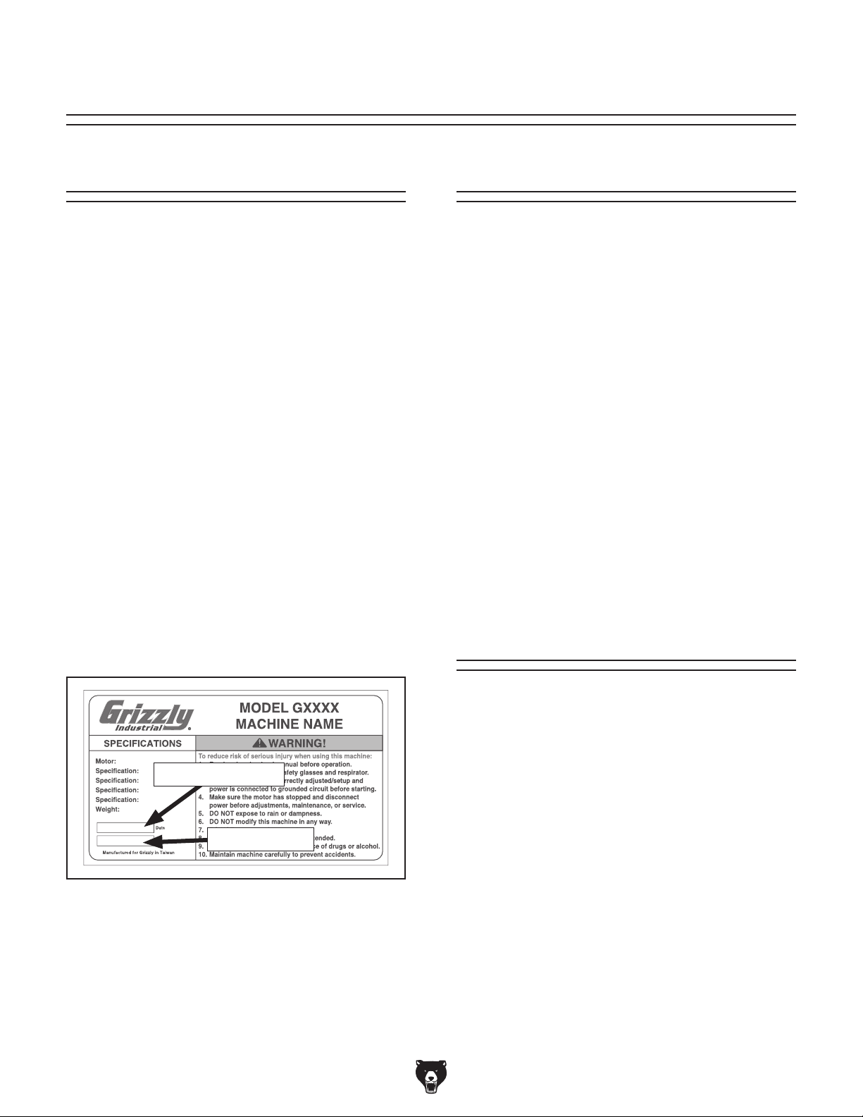
Identification ................................................... 3
Machine Data Sheet ...................................... 4
SECTION 1: SAFETY....................................... 6
Safety Instructions for Machinery .................. 6
Additional Safety for Boring Machines ........... 8
SECTION 2: POWER SUPPLY ........................ 9
Availability .................................................... 9
Full-Load Current Rating ............................. 9
Circuit Information ....................................... 9
Circuit Requirements for 110V .................... 9
Circuit Requirements for 220V .................... 9
Grounding Requirements .......................... 10
Extension Cords ........................................ 10
Voltage Conversion ................................... 11
SECTION 3: SETUP ....................................... 12
Needed for Setup ......................................... 12
Unpacking .................................................... 12
Inventory ...................................................... 13
Cleanup ........................................................ 13
Site Considerations ...................................... 14
Weight Load .............................................. 14
Space Allocation ........................................ 14
Physical Environment ................................ 14
Electrical Installation .................................. 14
Lighting ...................................................... 14
Lifting & Placing ........................................... 15
Mounting ...................................................... 15
Assembly ..................................................... 16
Dust Collection ............................................. 19
Power Connection........................................ 19
Connecting Power ..................................... 19
Disconnecting Power ................................. 19
Test Run ...................................................... 20
SECTION 4: OPERATIONS ........................... 21
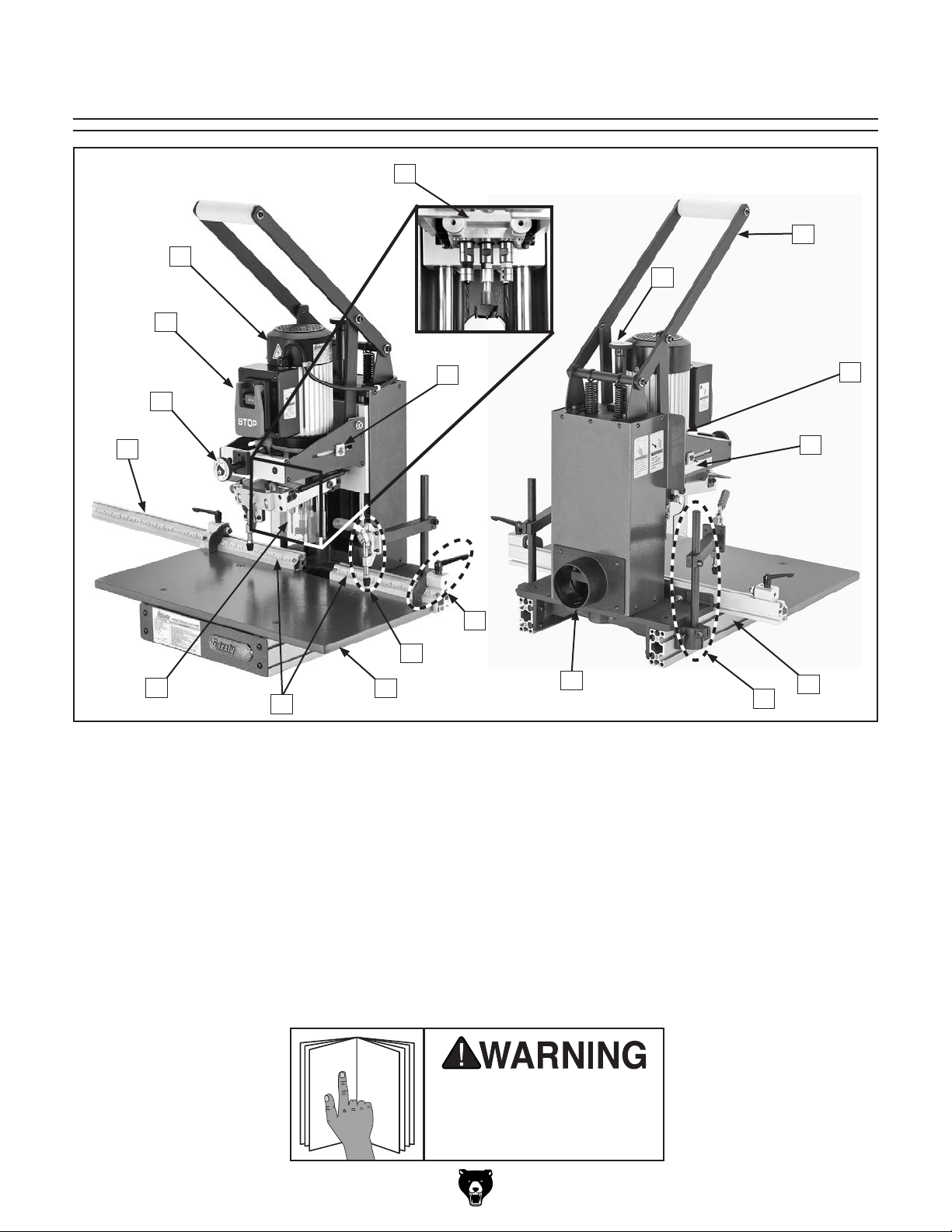
Basic Controls .............................................. 21
Disabling & Locking Switch.......................... 22
Setup Overview............................................ 22
Operation Overview ..................................... 22
Hold-Down Clamps ...................................... 23
Boring Head Setup ...................................... 24
Selecting Boring Head & Bits .................... 24
Replacing Boring Head ............................. 24
Installing & Adjusting Boring Bits .............. 25
Headstock Setup.......................................... 26
Drilling Depth ............................................. 27
Setback Distance ....................................... 27
Operation ................................................... 28
Swing Arm Test Fit & Adjustment ............. 28
Fence Stop Setup ........................................ 29
Determining Number of Hinges ................. 29
Two-Hinge Door ........................................ 30
Three-Hinge Door ...................................... 30
Four-Hinge Door ........................................ 31
SECTION 5: ACCESSORIES ......................... 32
SECTION 6: MAINTENANCE......................... 35
Schedule ...................................................... 35
Cleaning ....................................................... 35
Lubrication ................................................... 35
Headstock Slides ....................................... 36
Depth & Throat Adjustment Shafts ............ 36
Pivot Points ................................................ 36
Boring Head Assembly .............................. 36
SECTION 7: SERVICE ................................... 37
Troubleshooting ........................................... 37
Motor & Electrical ...................................... 37
Operation ................................................... 38
SECTION 8: WIRING...................................... 39
Wiring Safety Instructions ............................ 39
Wiring Diagram ............................................ 40
110V Wiring ............................................... 40
Machine Re-wired for 220V ....................... 40
SECTION 9: PARTS....................................... 41
Body ............................................................. 41
Table ............................................................ 43
Headstock .................................................... 44
Handle .......................................................... 45
Machine Labels ............................................ 46
WARRANTY AND RETURNS ........................ 49

-2- Model G0718 (Mfd. Since 12/10)
INTRODUCTION
The Model G0718 is a production machine
designed for drilling and installing European-style
hinges in cabinet doors.
Grizzly offers are a number of different boring
heads and interchangeable boring bits (all sold
separately), so the machine can be used for a
wide variety of different hinge brands.
The stock machine excels at large production
runs of 2-hinge doors. It is supplied with all the
components necessary to make small runs of
3- or 4-hinge doors; however, an additional exten-
sion fence and stops are recommended to expe-
dite larger or more frequent runs requiring 3 or 4
hinges.
Machine Description
We are proud to provide a high-quality owner’s
manual with your new machine!
We
made every effort to be exact with the
instruc-
tions, specifications, drawings, and photographs
in this manual. Sometimes we make mistakes, but
our policy of continuous improvement also means
that
sometimes the machine
you receive is
slightly different than shown in the manual
.
If you find this to be the case, and the difference
between the manual and machine leaves you
confused or unsure about something
,
check our
website for an updated version. W
e post
current
manuals and
manual updates for free
on our web-
site at
www.grizzly.com.
Alternatively, you can call our Technical Support
for help. Before calling, make sure you write down
the
Manufacture Date and Serial Number
from
the machine ID label (see below). This information
is required for us to provide proper tech support,
and it helps us determine if updated documenta-
tion is available for your machine.
Manufacture Date
Serial Number
Manual Accuracy
We stand behind our machines! If you have ques-
tions or need help, contact us with the information
below. Before contacting, make sure you get the
serial number
and manufacture date
from the
machine ID label. This will help us help you faster.
Grizzly Technical Support
1815 W. Battlefield
Springfield, MO 65807
Phone: (570) 546-9663
Email: [email protected]
We want your feedback on this manual. What did
you like about it? Where could it be improved?
Please take a few minutes to give us feedback.
Grizzly Documentation Manager
P.O. Box 2069
Bellingham, WA 98227-2069
Email: [email protected]
Contact Info

Model G0718 (Mfd. Since 12/10) -3-
Figure 1. Model G0718 controls and features.
A. Fence Extension w/Left Scale
B. Throat Adjustment Knob
C. ON/OFF Switch Assembly
D. Drive Motor
E. Boring Head Assembly w/Bits (Sold
Separately)
F. Throat Position Lock
G. Depth Adjustment Knob
H. Downfeed Handle
I. Depth Position Scale
Identification
A
N
E
G
H
D
C
P
O
RQ
B
J
M
F
LK
J. Throat Position Scale
K. Table Support w/Hold-Down Track
L. Hold-Down Base & Arm Assembly
M. 4" Dust Port
N. Fence Stops
O. Hold-Down Clamp
P. Work Table
Q. Table Fence Set
R. Boring Head Guard
I
To reduce your risk of
serious injury, read this
entire manual BEFORE
using machine.

-4- Model G0718 (Mfd. Since 12/10)
Machine Data Sheet
model G0718
HinGe borinGmacHine
© Grizzly Industrial, Inc. • Customer Service: (800) 523-4777 • Website: www.grizzly.com
macHine daTa
SHeeT
Product Dimensions:
Weight ........................................................................................................................................................................... 154 lbs.
Width (side-to-side) x Depth (front-to-back) x Height ..................................................................................29 x 25 x 36-5/8 in.
Foot Print (Length x Width) ........................................................................................................................... 15-1/2 x 22-1/2 in.
Shipping Dimensions:
Type ........................................................................................................................................... Cardboard Top & Wood Pallet
Content .......................................................................................................................................................................... Machine
Weight ............................................................................................................................................................................ 198 lbs.
Length/Width/Height ...........................................................................................................................................32 x 29 x 35 in.
Electrical:
Power Requirement ...............................................................................................................110V/220V, Single-Phase, 60 Hz
Pre-Wired Voltage .............................................................................................................................................................. 110V
Full-Load Current Rating .....................................................................................................................10A at 110V, 5A at 220V
Minimum Circuit Size ........................................................................................................................15A at 110V, 15A at 220V
Switch ...........................................................................................ON/OFF Switch w/Emergency Stop Paddle & Anti-Start Pin
Switch Voltage .......................................................................................................................................................... 110V/220V
Cord Length ..........................................................................................................................................................................9 ft.
Cord Gauge .................................................................................................................................................................. 14 AWG
Plug Included ........................................................................................................................................................................Yes
Included Plug Type ................................................................................................................................... NEMA 5-15 for 110V
Recommended Plug/Outlet Type .............................................................................................................. NEMA 6-15 for 220V
Motors:
Main
Type ......................................................................................................................................................................... TEFC
Horsepower ...............................................................................................................................................................1 HP
Voltage ............................................................................................................................................................ 110V/220V
Prewired ................................................................................................................................................................... 110V
Phase .......................................................................................................................................................... Single-Phase
Amps ....................................................................................................................................................................... 10/5A
Speed ...............................................................................................................................................................3440 RPM
Cycle ........................................................................................................................................................................ 60 Hz
Number Of Speeds ..........................................................................................................................................................1
Power Transfer ...............................................................................................................................................Direct Drive
Bearings ..................................................................................................................... Shielded and Permanently Sealed
Main Specifications:
Operation Information
Maximum Depth of Stroke ..........................................................................................................................................4 in.
Maximum Boring Depth from Edge ............................................................................................................................4 in.
Model G0718 Page 1 of 2

Model G0718 (Mfd. Since 12/10) -5-
Other Information
Boring Bit Shaft Thread ...........................................................................................................................................10mm
Rear Fence ................................................................................................................................... 12 in. Right, 12 in. Left
Extension Fence .......................................................................................................................................................28 in.
Back Fence Stop ...................................................................................................................................................2 Piece
Number of Spindles on Boring Head .....................................................................................3 Spindles (2 Left, 1 Right)
Construction
Rail Shaft Construction ...................................................................... SUJ-2 High Carbon Anti-Friction Steel Slide Shaft
Boring Head Construction .................................................................................................................................Aluminum
Headstock Construction ................................................................................................................................ Sheet Metal
Guard ................................................................................................................................................................Clear PVC
Head Carriage ..........................................................................................................................................Aluminum Alloy
Motor Seat ................................................................................................................................................Aluminum Alloy
Table ........................................................................................................................................................ Laminated MDF
Paint .........................................................................................................................................................Powder Coated
Other Related Infomation
Swing Boring Head Tolerance ......................................................................................................................... +/- 0.2mm
Number of Dust Ports ......................................................................................................................................................1
Dust Port Size ............................................................................................................................................................4 in.
Other Specifications:
Country Of Origin ............................................................................................................................................................ Taiwan
Warranty ........................................................................................................................................................................... 1 Year
Serial Number Location ...........................................................................................................ID Label on Center of the Stand
Customer Cleanup and Assembly Time ................................................................................................................... 30 Minutes
Features:
Swing boring head tolerance +/- 0.2mm
Downfeed stroke scale position indicator
Rear fence scale position indicator
28" extension fence
Manual stroke operation
Model G0718 Page 2 of 2

-6- Model G0718 (Mfd. Since 12/10)
ELECTRICAL EQUIPMENT INJURY RISKS. You
can be shocked, burned, or killed by touching live
electrical components or improperly grounded
machinery. To reduce this risk, only allow qualified
service personnel to do electrical installation or
repair work, and always disconnect power before
accessing or exposing electrical equipment.
DISCONNECT POWER FIRST.
Always discon-
nect machine from power supply BEFORE making
adjustments, changing tooling, or servicing machine.
This prevents an injury risk from unintended startup
or contact with live electrical components.
EYE PROTECTION. Always wear ANSI-approved
safety glasses or a face shield when operating or
observing machinery to reduce the risk of eye
injury or blindness from flying particles. Everyday
eyeglasses are NOT approved safety glasses.
OWNER’S MANUAL. Read and understand this
owner’s manual BEFORE using machine.
TRAINED OPERATORS ONLY. Untrained oper-
ators have a higher risk of being hurt or killed.
Only allow trained/supervised people to use this
machine. When machine is not being used, dis-
connect power, remove switch keys, or lock-out
machine to prevent unauthorized use—especially
around children. Make your workshop kid proof!
DANGEROUS ENVIRONMENTS. Do not use
machinery in areas that are wet, cluttered, or have
poor lighting. Operating machinery in these areas
greatly increases the risk of accidents and injury.
MENTAL ALERTNESS REQUIRED. Full mental
alertness is required for safe operation of machin-
ery. Never operate under the influence of drugs or
alcohol, when tired, or when distracted.
For Your Own Safety, Read Instruction
Manual Before Operating This Machine
The purpose of safety symbols is to attract your attention to possible hazardous conditions.
This manual uses a series of symbols and signal words intended to convey the level of impor-
tance of the safety messages. The progression of symbols is described below. Remember that
safety messages by themselves do not eliminate danger and are not a substitute for proper
accident prevention measures. Always use common sense and good judgment.
Indicates a potentially hazardous situation which, if not avoided,
MAY result in minor or moderate injury. It may also be used to alert
against unsafe practices.
Indicates a potentially hazardous situation which, if not avoided,
COULD result in death or serious injury.
Indicates an imminently hazardous situation which, if not avoided,
WILL result in death or serious injury.
This symbol is used to alert the user to useful information about
proper operation of the machine.
NOTICE
Safety Instructions for Machinery
SECTION 1: SAFETY

Model G0718 (Mfd. Since 12/10) -7-
WEARING PROPER APPAREL. Do not wear
clothing, apparel or jewelry that can become
entangled in moving parts. Always tie back or
cover long hair. Wear non-slip footwear to reduce
risk of slipping and losing control or accidentally
contacting cutting tool or moving parts.
HAZARDOUS DUST. Dust created by machinery
operations may cause cancer, birth defects, or
long-term respiratory damage. Be aware of dust
hazards associated with each workpiece mate-
rial. Always wear a NIOSH-approved respirator to
reduce your risk.
HEARING PROTECTION. Always wear hear-
ing protection when operating or observing loud
machinery. Extended exposure to this noise
without hearing protection can cause permanent
hearing loss.
REMOVE ADJUSTING TOOLS. Tools left on
machinery can become dangerous projectiles
upon startup. Never leave chuck keys, wrenches,
or any other tools on machine. Always verify
removal before starting!
USE CORRECT TOOL FOR THE JOB. Only use
this tool for its intended purpose—do not force
it or an attachment to do a job for which it was
not designed. Never make unapproved modifica-
tions—modifying tool or using it differently than
intended may result in malfunction or mechanical
failure that can lead to personal injury or death!
AWKWARD POSITIONS. Keep proper footing
and balance at all times when operating machine.
Do not overreach! Avoid awkward hand positions
that make workpiece control difficult or increase
the risk of accidental injury.
CHILDREN & BYSTANDERS. Keep children and
bystanders at a safe distance from the work area.
Stop using machine if they become a distraction.
GUARDS & COVERS. Guards and covers reduce
accidental contact with moving parts or flying
debris. Make sure they are properly installed,
undamaged, and working correctly BEFORE
operating machine.
FORCING MACHINERY. Do not force machine.
It will do the job safer and better at the rate for
which it was designed.
NEVER STAND ON MACHINE. Serious injury
may occur if machine is tipped or if the cutting
tool is unintentionally contacted.
STABLE MACHINE. Unexpected movement dur-
ing operation greatly increases risk of injury or
loss of control. Before starting, verify machine is
stable and mobile base (if used) is locked.
USE RECOMMENDED ACCESSORIES. Consult
this owner’s manual or the manufacturer for rec-
ommended accessories. Using improper acces-
sories will increase the risk of serious injury.
UNATTENDED OPERATION. To reduce the
risk of accidental injury, turn machine OFF and
ensure all moving parts completely stop before
walking away. Never leave machine running
while unattended.
MAINTAIN WITH CARE. Follow all maintenance
instructions and lubrication schedules to keep
machine in good working condition. A machine
that is improperly maintained could malfunction,
leading to serious personal injury or death.
DAMAGED PARTS. Regularly inspect machine
for damaged, loose, or mis-adjusted parts—or
any condition that could affect safe operation.
Immediately repair/replace BEFORE operating
machine. For your own safety, DO NOT operate
machine with damaged parts!
MAINTAIN POWER CORDS. When disconnect-
ing cord-connected machines from power, grab
and pull the plug—NOT the cord. Pulling the cord
may damage the wires inside. Do not handle
cord/plug with wet hands. Avoid cord damage by
keeping it away from heated surfaces, high traffic
areas, harsh chemicals, and wet/damp locations.
EXPERIENCING DIFFICULTIES. If at any time
you experience difficulties performing the intend-
ed operation, stop using the machine! Contact our
Technical Support at (570) 546-9663.

-8- Model G0718 (Mfd. Since 12/10)
No list of safety guidelines can be complete.
Every shop environment is different. Always
consider safety first, as it applies to your
individual working conditions. Use this and
other machinery with caution and respect.
Failure to do so could result in serious per-
sonal injury, damage to equipment, or poor
work results.
Like all machinery there is potential danger
when operating this machine. Accidents are
frequently caused by lack of familiarity or
failure to pay attention. Use this machine
with respect and caution to decrease the
risk of operator injury. If normal safety pre-
cautions are overlooked or ignored, serious
personal injury may occur.
Additional Safety for Boring Machines
EYE/FACE/HAND PROTECTION. Debris from
the drilling operation can be thrown at the operator.
Always wear safety glasses or a face shield to pro-
tect your eyes and face during boring operations.
The spinning boring bits are sharp and can cause
serious injury. Always keep hands and fingers
away from the moving bits. To reduce the risk of
entanglement, DO NOT wear gloves when operat-
ing this machine.
GUARDS. The boring head guard reduces the risk
of debris being thrown at the operator. DO NOT
operate this machine with this guard removed.
BORING OPERATION. The boring bits rotate with
tremendous torque, especially at start up. To avoid
the bits grabbing the workpiece and unexpectedly
moving it, never start the machine with the boring
bits pressed against the workpiece.
DULL OR WORN BITS. Dull or damaged bits may
break apart during operation, be thrown at the
operator, or reduce the performance of the opera-
tion. Inspect bits before each use. DO NOT oper-
ate with dull or damaged bits.
SECURING WORKPIECE. The operator's hands
may be drawn into the spinning boring bits if the
workpiece moves unexpectedly during operation.
Make sure the workpiece is firmly against the
fence, and the workpiece is fully secured with the
hold-downs.
BORING BITS. A rapidly spinning boring bit can
be thrown at the operator if it comes loose from
the chuck. Only use boring bits with a 10mm shank
designed for this machine. Properly secure the bits
in the chucks before beginning operations.
SURFACE/WORKPIECE PREPARATION. Never
turn the machine ON before clearing the table of
all tools, scrap wood, etc. Only drill wood products
that are free of imperfections or foreign objects.
Never use this machine to drill metal.
EXPERIENCING DIFFICULTIES. If at any time you
are experiencing difficulties performing the intend-
ed operation, stop using the machine! Contact our
Technical Support at (570) 546-9663.

Model G0718 (Mfd. Since 12/10) -9-
SECTION 2: POWER SUPPLY
Availability
Before installing the machine, consider the avail-
ability and proximity of the required power supply
circuit. If an existing circuit does not meet the
requirements for this machine, a new circuit must
be installed. To minimize the risk of electrocution,
fire, or equipment damage, installation work and
electrical wiring must be done by an electrician or
qualified service personnel in accordance with all
applicable codes and standards.
Electrocution, fire, shock,
or equipment damage
may occur if machine is
not properly grounded
and connected to power
supply.
Full-Load Current Rating
The full-load current rating is the amperage a
machine draws at 100% of the rated output power.
On machines with multiple motors, this is the
amperage drawn by the largest motor or sum of all
motors and electrical devices that might operate
at one time during normal operations.
Full-Load Current Rating at 110V...... 10 Amps
Full-Load Current Rating at 220V ....... 5 Amps
The full-load current is not the maximum amount
of amps that the machine will draw. If the machine
is overloaded, it will draw additional amps beyond
the full-load rating.
If the machine is overloaded for a sufficient length
of time, damage, overheating, or fire may result—
especially if connected to an undersized circuit.
To reduce the risk of these hazards, avoid over-
loading the machine during operation and make
sure it is connected to a power supply circuit that
meets the specified circuit requirements.
For your own safety and protection of
property, consult an electrician if you are
unsure about wiring practices or electrical
codes in your area.
Note: Circuit requirements in this manual apply to
a dedicated circuit—where only one machine will
be running on the circuit at a time. If machine will
be connected to a shared circuit where multiple
machines may be running at the same time, con-
sult an electrician or qualified service personnel to
ensure circuit is properly sized for safe operation.
A power supply circuit includes all electrical
equipment between the breaker box or fuse panel
in the building and the machine. The power sup-
ply circuit used for this machine must be sized to
safely handle the full-load current drawn from the
machine for an extended period of time. (If this
machine is connected to a circuit protected by
fuses, use a time delay fuse marked D.)
Circuit Information
Circuit Requirements for 220V
Nominal Voltage ......... 208V, 220V, 230V, 240V
Cycle ..........................................................60 Hz
Phase ........................................... Single-Phase
Power Supply Circuit ......................... 15 Amps
Plug/Receptacle ............................. NEMA 6-15
This machine can be converted to operate on a
power supply circuit that has a verified ground
and meets the requirements listed below. (Refer
to Voltage Conversion instructions for details.)
This machine is prewired to operate on a power
supply circuit that has a verified ground and meets
the following requirements:
Circuit Requirements for 110V
Nominal Voltage .................... 110V, 115V, 120V
Cycle ..........................................................60 Hz
Phase ........................................... Single-Phase
Power Supply Circuit ......................... 15 Amps
Plug/Receptacle ............................. NEMA 5-15

-10- Model G0718 (Mfd. Since 12/10)
Improper connection of the equipment-grounding
wire can result in a risk of electric shock. The
wire with green insulation (with or without yellow
stripes) is the equipment-grounding wire. If repair
or replacement of the power cord or plug is nec-
essary, do not connect the equipment-grounding
wire to a live (current carrying) terminal.
Check with a qualified electrician or service per-
sonnel if you do not understand these grounding
requirements, or if you are in doubt about whether
the tool is properly grounded. If you ever notice
that a cord or plug is damaged or worn, discon-
nect it from power, and immediately replace it with
a new one.
Extension Cords
We do not recommend using an extension cord
with this machine.
If you must use an extension
cord, only use it if absolutely necessary and only
on a temporary basis.
Extension cords cause voltage drop, which can
damage electrical components and shorten motor
life. Voltage drop increases as the extension cord
size gets longer and the gauge size gets smaller
(higher gauge numbers indicate smaller sizes).
Any extension cord used with this machine must
be in good condition and contain a ground wire
and matching plug/receptacle. Additionally, it must
meet the following size requirements:
Minimum Gauge Size ...........................14 AWG
Maximum Length (Shorter is Better).......50 ft.
Grounding Requirements
This machine MUST be grounded. In the event
of certain malfunctions or breakdowns, grounding
reduces the risk of electric shock by providing a
path of least resistance for electric current.
Figure 2. Typical 5-15 plug and receptacle.
Grounding Prong
Neutral Hot
5-15 PLUG
GROUNDED
5-15 RECEPTACLE
Figure 3. Typical 6-15 plug and receptacle.
Grounding Prong
Current Carrying Prongs
6-15 PLUG
GROUNDED
6-15 RECEPTACLE
For 110V operation: This machine is equipped
with a power cord that has an equipment-ground-
ing wire and a grounding plug (see following fig-
ure). The plug must only be inserted into a match-
ing receptacle (outlet) that is properly installed
and grounded in accordance with all local codes
and ordinances.
For 220V operation: The plug specified under
“
Circuit Requirements for 220V” on the previous
page has a grounding prong that must be attached
to the equipment-grounding wire on the included
power cord. The plug must only be inserted into
a matching receptacle (see following figure) that
is properly installed and grounded in accordance
with all local codes and ordinances.
SHOCK HAZARD!
Two-prong outlets do not meet the grounding
requirements for this machine. Do not modify
or use an adapter on the plug provided—if
it will not fit the outlet, have a qualified
electrician install the proper outlet with a
verified ground.

Model G0718 (Mfd. Since 12/10) -11-
Voltage Conversion
This section shows how to convert the Model
G0718 from 110V to 220V. The plug needed for
this conversion can be purchased at any local
hardware store or electrical supply store.
Items Needed Qty
• Phillips Head Screwdriver #2 ..................... 1
• NEMA 6-15 Plug ......................................... 1
• Wire Cutters ............................................... 1
• Wire Strippers ............................................. 1
5. Reposition wires 1–4 as shown in Figure 6,
then tighten the screws loosened in Step 4.
6. Close and secure the motor junction box.
7. Install a 6-15 plug on the end of the cord,
according to the instructions and wiring dia-
grams provided by the plug manufacturer.
—If instructions and a wiring diagram are not
provided by the plug manufacturer, the wir-
ing diagram shown on Page 40 shows the
wiring of a standard NEMA 6-15 plug. This
diagram may be used as long as your plug
matches the one shown.
Figure 6. Motor rewired for 220V.
Hot
Hot
Ground
6-15 Plug
(As Recommended)
220
VAC
G
Motor
ON
STOP
Start Capacitor
300MFD 125VAC
Run Capacitor
50MFD 250VAC
Rd Rd Rd Rd
Rd
Rd
Rd Rd
Wt
Gn
Gn
GND
Bk
1
3
2
4
Neutral
Hot
Ground
110 VAC
5-15 Plug
220 VAC
Wt
Bk
1
3
2
4
ON
STOP
Start Capacitor
300MFD 125VAC
Run Capacitor
50MFD 250VAC
Rd
Rd Rd Rd
Rd
Rd
Rd Rd
Wt
Gn
Gn
GND
Bk
1
32
4
Wt
Bk
1
3
2
4
Motor
Figure 5. Location of screws to be loosened.
Hot
Hot
Ground
6-15 Plug
(As Recommended)
220
VAC
G
Motor
ON
STOP
Start Capacitor
300MFD 125VAC
Run Capacitor
30MFD 250VAC
Rd
Rd Rd Rd
Rd
Rd
Rd Rd
Wt
Gn
Gn
GND
Bk
1
3
2
4
Neutral
Hot
Ground
110 VAC
5-15 Plug
220 VAC
Wt
Bk
1
3
2
4
ON
STOP
Start Capacitor
300MFD 125VAC
Run Capacitor
30MFD 250VAC
Rd Rd Rd Rd
Rd
Rd
Rd Rd
Wt
Gn
Gn
GND
Bk
1
32
4
Wt
Bk
1
3
2
4
Motor
Loosen
These
Screws
4. Loosen the screws indicated in Figure 5.
NOTICE
This manual was current at the time of print-
ing; however, if the wiring diagram provided
on the inside cover of the motor junction
box conflicts with this manual, always use
that wiring diagram instead, as it will reflect
any changes that may have occurred after
printing.
To convert to 220V:
1. DISCONNECT BORING MACHINE FROM
POWER!
2. Cut off the pre-installed 5-15 plug from the
end of the power cord.
3. Open the motor junction box (see Figure 4)
by removing the four screws from the front.
Figure 4. Motor junction box and screw
locations.
Junction Box

-12- Model G0718 (Mfd. Since 12/10)
Wear safety glasses dur-
ing the entire setup pro-
cess!
This machine presents
serious injury hazards
to untrained users. Read
through this entire manu-
al to become familiar with
the controls and opera-
tions before starting the
machine!
SECTION 3: SETUP
The following are needed to complete the setup
process, but are not included with your machine.
Description Qty
• Safety Glasses ........................................... 1
• Degreaser or Solvent for Cleaning ..... Varies
• Rags for Cleaning ............................... Varies
• Minimum People Required for Lifting ......... 3
• Screwdriver Phillips #2 ............................... 1
• Dust Collection System .............................. 1
• Dust Hose 4" .............................................. 1
• Hose Clamps 4" ......................................... 2
Needed for Setup
This machine and its com-
ponents are very heavy.
Get lifting help or use
power lifting equipment
such as a forklift to move
heavy items.
This machine was carefully packaged for safe
transport. When unpacking, separate all enclosed
items from packaging materials and inspect them
for shipping damage.
If items are damaged
,
please
call us immediately at (570) 546-9663.
IMPORTANT:
Save all packaging materials until
you are completely satisfied with the machine and
have resolved any issues between Grizzly or the
shipping agent. You MUST have the original pack-
aging to file a freight claim. It is also extremely
helpful if you need to return your machine later.
Unpacking
SUFFOCATION HAZARD!
Keep children and pets away
from plastic bags or packing
materials shipped with this
machine. Discard immediately.

Model G0718 (Mfd. Since 12/10) -13-
Figure 7. Inventory.
Box 1: (Figure 7) Qty
A. Boring Machine (Not Shown) ..................... 1
B. Fence Extension w/Scale ........................... 1
C. Right Scale (1415 ⁄16"–42") ............................ 1
D. Dust Port 4" ................................................ 1
E. Boring Head Guard .................................... 1
F. Swing Arm Assembly ................................. 1
G. Open-End Wrench 14/17mm ...................... 1
H. Open-End Wrench 12/14mm ...................... 1
I. Open-End Wrench 11/13mm ...................... 1
J. Cap Screws M6-1 x 65 ............................... 4
K. Cap Screws M6-1 x 55 ............................... 2
L. Cap Screws M6-1 x 45 ............................... 2
M. Hex Wrench Set
1.5, 2, 2.5, 3, 4, 5, 6, 8, & 10mm .......1 Each
B
DE
F
G
H
IJKLM
C
Inventory
The following is a list of items shipped with your
machine. Before beginning setup, lay these items
out and inventory them.
If any non-proprietary parts are missing (e.g. a
nut or a washer), we will gladly replace them; or
for the sake of expediency, replacements can be
obtained at your local hardware store.
Cleanup
The unpainted surfaces of your machine are
coated with a heavy-duty rust preventative that
prevents corrosion during shipment and storage.
This rust preventative works extremely well, but it
will take a little time to clean.
Be patient and do a thorough job cleaning your
machine. The time you spend doing this now will
give you a better appreciation for the proper care
of your machine's unpainted surfaces.
There are many ways to remove this rust preven-
tative, but the following steps work well in a wide
variety of situations. Always follow the manufac-
turer’s instructions with any cleaning product you
use and make sure you work in a well-ventilated
area to minimize exposure to toxic fumes.
Before cleaning, gather the following:
• Disposable rags
• Cleaner/degreaser (WD•40 works well)
• Safety glasses & disposable gloves
• Plastic paint scraper (optional)
Basic steps for removing rust preventative:
1.
Put on safety glasses.
2.
Coat the rust preventative with a liberal
amount of cleaner/degreaser, then let it soak
for 5–10 minutes.
3.
Wipe off the surfaces. If your cleaner/degreas-
er is effective, the rust preventative will wipe
off easily. If you have a plastic paint scraper,
scrape off as much as you can first, then wipe
off the rest with the rag.
4.
Repeat Steps 2–3 as necessary until clean,
then coat all unpainted surfaces with a quality
metal protectant to prevent rust.
NOTICE
Avoid chlorine-based solvents, such as
acetone or brake parts cleaner, that may
damage painted surfaces.

-14- Model G0718 (Mfd. Since 12/10)
Figure 8. Minimum working clearances.
57" 28"
25"
Dust
Power
Supply
Port
29"
Site Considerations
Weight Load
Refer to the
Machine Data Sheet for the weight
of your machine. Make sure that the surface upon
which the machine is placed will bear the weight
of the machine, additional equipment that may be
installed on the machine, and the heaviest work-
piece that will be used. Additionally, consider the
weight of the operator and any dynamic loading
that may occur when operating the machine.
Space Allocation
Consider the largest size of workpiece that will
be processed through this machine and provide
enough space around the machine for adequate
operator material handling or the installation of
auxiliary equipment. With permanent installations,
leave enough space around the machine to open
or remove doors/covers as required by the main-
tenance and service described in this manual.
See below for required space allocation.
Physical Environment
The physical environment where the machine is
operated is important for safe operation and lon-
gevity of machine components. For best results,
operate this machine in a dry environment that is
free from excessive moisture, hazardous chemi-
cals, airborne abrasives, or extreme conditions.
Extreme conditions for this type of machinery are
generally those where the ambient temperature
range exceeds 41°–104°F; the relative humidity
range exceeds 20%–95% (non-condensing); or
the environment is subject to vibration, shocks,
or bumps.
Electrical Installation
Place this machine near an existing power source.
Make sure all power cords are protected from
traffic, material handling, moisture, chemicals, or
other hazards. Make sure to leave enough space
around machine to disconnect power supply or
apply a lockout/tagout device, if required.
Lighting
Lighting around the machine must be adequate
enough that operations can be performed safely.
Shadows, glare, or strobe effects that may distract
or impede the operator must be eliminated.
Children or untrained people
may be seriously injured by
this machine. Only install in an
access restricted location.

Model G0718 (Mfd. Since 12/10) -15-
Lifting & Placing
To lift and place your boring machine:
1. Prepare the location for the boring machine
per Circuit Requirements on Page 9 and
Site Considerations on Page 14.
2. Unbolt the machine from the shipping crate.
3. Lift from each side of the work table, and
move the machine to its prepared location.
Minimum 3-person lift! This
machine and its compo-
nents are very heavy. Use
safe lifting methods when
moving this machine.
Mounting
Figure 10. "Direct Mount" setup.
Machine Base
Workbench
Lag Screw
Flat Washer
Another option is a "direct mount" (see example
below) where the machine is secured directly to
the workbench with lag screws and washers.
The base of this machine has mounting holes
that allow it to be fastened to a workbench or
other mounting surface to prevent it from moving
during operation and causing accidental injury or
damage.
The strongest mounting option is a "Through
Mount" (see example below) where holes are
drilled all the way through the workbench—and
hex bolts, washers, and hex nuts are used to
secure the machine in place.
Machine Base
Workbench
Hex
Bolt
Flat Washer
Flat Washer
Lock Washer
Hex Nut
Figure 9. "Through Mount" setup.

-16 - Model G0718 (Mfd. Since 12/10)
Assembly 3. Remove the fasteners from the pivot connec-
tor (see Figure 11), raise the handle pivot
bar, and use the fasteners to secure the han-
dle pivot bar to the vertical pivot bar through
the mounting holes shown.
4. Loosen the cap screws on the fence exten-
sion rods, slide the rods out about half their
length (see Figure 12), then tighten two of the
screws to secure the rods to the extension.
The handle was secured to the machine in a spe-
cial way to protect it from shipping damage. As
such, the way it is mounted for shipping is not how
it should be mounted for operation. The assembly
process involves re-mounting the handle in its
operating position and installing all loose compo-
nents from the shipping box.
The machine requires, but does not include,
a boring head in order to perform operations.
Grizzly offers a number of boring heads for this
machine (refer to Page 32 for more details). The
boring head must be installed before performing
the Test Run procedure. To choose the correct
boring head, refer to Selecting Boring Head on
Page 24.
Serious personal injury could occur if you
connect the machine to power before com-
pleting the setup process. DO NOT connect
power until instructed later in this manual.
To assemble your boring machine:
1. DISCONNECT BORING MACHINE FROM
POWER!
2. Remove and discard the cable ties that
secure the downfeed handle (see Figure 11).
Figure 11. Cable ties and pivot connector.
Vertical Pivot Bar
Pivot Connector
Mounting
Hole
Cable Tie
(1 of 2)
Handle Pivot Bar
Note: The fence extension is only needed for
certain applications, such as 3-hinge doors.
Therefore, installation is optional depending
on anticipated needs.
The fence extension can be mounted on the
left or right end of the table fence for different
applications. If mounting the fence extension
on the right side, you must swap the left scale
on the fence extension with the provided right
scale. This ensures the numbering sequence
between the table fence scale and the fence
extension scale are congruent.
Figure 12. Fence extension rods and cap
screws (shown from right rear of table).
Cap
Screw
Fence
Extension
Rods
Cap
Screw
Table
Fence
Fence
Extension

Model G0718 (Mfd. Since 12/10) -17-
5. Slide the fence extension rods into the table
fence, then tighten the cap screws to hold the
fence extension in place (see Figure 13).
Note: If you decide not to install the fence
extension at this time, it can be set aside with
the extension rods and stored for later use.
7. Mount the boring head to the spindle, making
sure the slot in the boring head shaft (see
Figure 15) is aligned with the tang in the
spindle.
Figure 15. Installing boring head on spindle.
Slot
Boring
Head
Spindle
8. Secure the boring head with (4) M6-1 x 65
cap screws at the inside holes shown in
Figure 16.
Figure 16. Securing boring head to machine.
M6-1 x 65 Cap Screws
(3 of 4 Shown)
Figure 13. Fence extension installed.
Figure 14. Dust port installed.
6. Install the dust port.

-18- Model G0718 (Mfd. Since 12/10)
10. Pivot the swing arm up and secure both sides
of the swing arm assembly to the head with
(2) M6-1 x 45 cap screws and (2) M6-1 x 55
cap screws, using each size where shown in
Figure 18.
11. Pivot the swing arm down.
12. Remove the swing arm handle, which is pre-
installed backwards for shipping purposes,
then re-install it as shown in Figure 19.
9. Slide the swing arm assembly over the boring
head (see Figure 17).
Figure 17. Sliding swing arm onto boring head.
Figure 19. Installing swing arm handle.
Handle
13. Install the clear guard (see Figure 20) with
the knurled knobs.
Figure 20. Clear guard installed.
Knurled Knobs
Figure 18. Securing swing arm assembly.
M6-1 x 55 Cap Screw
(1 of 2 Shown)
M6-1 x 45 Cap
Screw
(1 of 2 Shown)
Table of contents
Other Grizzly Industrial Equipment manuals

Grizzly
Grizzly G9933 User manual

Grizzly
Grizzly T32710 User manual

Grizzly
Grizzly T32716 User manual

Grizzly
Grizzly G0708 User manual

Grizzly
Grizzly G0708 User manual

Grizzly
Grizzly G0479 User manual

Grizzly
Grizzly T32841 User manual

Grizzly
Grizzly G3102 User manual

Grizzly
Grizzly G0757Z User manual

Grizzly
Grizzly T24631 User manual

Grizzly
Grizzly G0877 User manual

Grizzly
Grizzly G0884 User manual

Grizzly
Grizzly G0937 User manual

Grizzly
Grizzly T33447 User manual

Grizzly
Grizzly T33850 User manual

Grizzly
Grizzly G9980 User manual

Grizzly
Grizzly G0731 User manual

Grizzly
Grizzly G0707 User manual

Grizzly
Grizzly G0656P User manual

Grizzly
Grizzly T32718 User manual