Grizzly G4003G User manual

COPYRIGHT © MAY, 2007 BY GRIZZLY INDUSTRIAL, INC., REVISED OCTOBER, 2007 (TR)
WARNING: NO PORTION OF THIS MANUAL MAY BE REPRODUCED IN ANY SHAPE
OR FORM WITHOUT THE WRITTEN APPROVAL OF GRIZZLY INDUSTRIAL, INC.
#CRTRTS9327 PRINTED IN CHINA
MODEL G4003G
GUNSMITH'S LATHE
OWNER'S MANUAL


G4003G Gunsmith's Lathe -1-
Table of Contents
INTRODUCTION ............................................... 2
Foreword ........................................................ 2
Contact Info ................................................... 2
Machine Data Sheet ...................................... 3
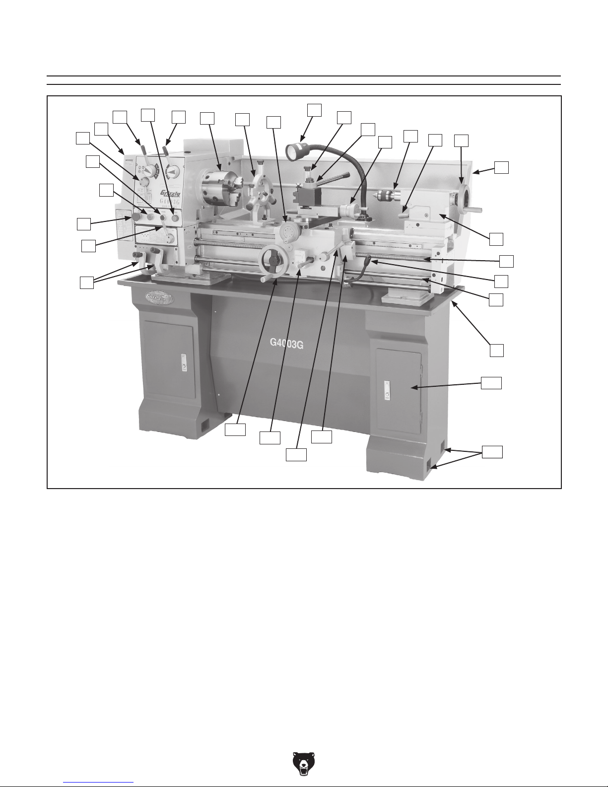
Identification ................................................... 5
SECTION 1: SAFETY ....................................... 6
Additional Safety Instructions for Lathes ....... 8
Glossary of Terms ......................................... 9
SECTION 2: CIRCUIT REQUIREMENTS ...... 10
220V Single-Phase ...................................... 10
SECTION 3: SETUP ....................................... 11
Setup Safety ................................................ 11
Items Needed for Setup ............................... 11
Unpacking .................................................... 11
Inventory ...................................................... 12
Site Considerations ...................................... 13
Clean Up ...................................................... 13
Mounting to Shop Floor ............................... 14
Cabinet Base Assembly ............................... 14
Lifting & Moving ........................................... 15
Test Run & Break-In ................................... 16
Tailstock Setup ............................................ 17
SECTION 4: OPERATION .............................. 19
Operation Safety .......................................... 19
Spindle Speeds ............................................ 19
Mounting Chuck and Faceplate .................. 20
Centers ........................................................ 22
Spider ........................................................... 22
Steady Rest ................................................. 23
Follow Rest .................................................. 23
Feed Direction Lever ................................... 24
Feed Rod Lever ........................................... 24
Gearbox Levers ........................................... 25
Feed Rate Chart .......................................... 25
Carriage/Cross Feed Lever ......................... 26
Half-Nut Lever and Inch Threading ............. 26
Change Gears and Metric Threading .......... 28
Carriage Handwheels .................................. 29
Tool Post & Holder ...................................... 30
Tailstock Controls ........................................ 30
SECTION 5: ACCESSORIES ......................... 31
SECTION 6: MAINTENANCE ......................... 33
Basic Maintenance ...................................... 33
Lubrication ................................................... 33
SECTION 7: SERVICE ................................... 35
Troubleshooting ........................................... 35
Gibs .............................................................. 37
Bearing Preload ........................................... 38
Wiring—Electrical Box ................................ 41
Wiring—Motor & Control Panel .................. 43
Wiring—Plug, Light & Spindle Switch ......... 45
SECTION 8: PARTS ....................................... 47
Components ................................................. 47
Gearbox Gearing ......................................... 48
Gearbox Shifters .......................................... 50
Quick Change System ................................. 52
Apron ........................................................... 54
Saddle .......................................................... 56
Compound Slide .......................................... 58
Tailstock ....................................................... 59
Lathe Bed & Motor ....................................... 60
Base ............................................................. 61
Feed Rod ..................................................... 63
Machine Labels ............................................ 64
Electrical Components ................................. 65
Steady & Follow Rest Assemblies ............... 66
WARRANTY AND RETURNS ........................ 69

-2- G4003G Gunsmith's Lathe
If you have any comments regarding this manual,
please write to us at the address below:
Grizzly Industrial, Inc.
C/O Technical Documentation Manager
P.O. Box 2069
Bellingham, WA 98227-2069
Email: [email protected]
We stand behind our machines. If you have any
service questions or parts requests, please call or
write us at the location listed below.
Grizzly Industrial, Inc.
1203 Lycoming Mall Circle
Muncy, PA 17756
Phone: (570) 546-9663
Fax: (800) 438-5901
E-Mail: [email protected]
Web Site: http://www.grizzly.com
Foreword
INTRODUCTION
Contact Info
We are proud to offer the Model G4003G
Gunsmith's Lathe. This machine is part of a grow-
ing Grizzly family of fine metalworking machinery.
When used according to the guidelines set forth in
this manual, you can expect years of trouble-free,
enjoyable operation and proof of Grizzly’s com-
mitment to customer satisfaction.
We are pleased to provide this manual with
the Model G4003G. It was written to guide you
through assembly, review safety considerations,
and cover general operating procedures. It repre-
sents our effort to produce the best documenta-
tion possible.
The specifications, drawings, and photographs
illustrated in this manual represent the Model
G4003G as supplied when the manual was pre-
pared. However, owing to Grizzly’s policy of con-
tinuous improvement, changes may be made at
any time with no obligation on the part of Grizzly.
For your convenience, we always keep current
Grizzly manuals available on our website at www.
grizzly.com. Any updates to your machine will be
reflected in these manuals as soon as they are
complete. Visit our site often to check for the lat-
est updates to this manual!

G4003G Gunsmith's Lathe -3-
The information contained herein is deemed accurate as of 11/12/2007 and represents our most recent product specifications.
Due to our ongoing improvement efforts, this information may not accurately describe items previously purchased. PAGE 1 OF 3Model G4003G
MACHINE DATA
SHEET
Customer Service #: (570) 546-9663 · To Order Call: (800) 523-4777 · Fax #: (800) 438-5901
MODEL G4003G GUNSMITH'S BENCH TOP LATHE WITH
STAND
Product Dimensions:
Weight............................................................................................................................................................ 1213 lbs.
Length/Width/Height....................................................................................................................... 61 x 26 x 54-1/2 in.
Foot Print (Length/Width)................................................................................................................. 57-1/2 x 14-1/2 in.
Shipping Dimensions:
Type........................................................................................................................................................... Wood Crate
Content............................................................................................................................................................ Machine
Weight............................................................................................................................................................ 1500 lbs.
Length/Width/Height............................................................................................................................. 65 x 30 x 61 in.
Electrical:
Switch...................................................................................................................................................On/Off Reverse
Switch Voltage...................................................................................................................................................... 220V
Cord Length...................................................................................................................................................... 5-1/2 ft.
Cord Gauge....................................................................................................................................................14 gauge
Recommended Breaker Size............................................................................................................................ 15 amp
Plug.......................................................................................................................................................................... No
Motors:
Main
Type.................................................................................................................. TEFC Capacitor Start Induction
Horsepower.................................................................................................................................................2 HP
Voltage........................................................................................................................................................220V
Prewired......................................................................................................................................................220V
Phase........................................................................................................................................................ Single
Amps.............................................................................................................................................................12A
Speed.................................................................................................................................................1725 RPM
Cycle..........................................................................................................................................................60 Hz
Number Of Speeds........................................................................................................................................... 1
Power Transfer ................................................................................................................... Twin V-Belt to Gear
Bearings........................................................................................................... Shielded and Lubricated for Life
Main Specifications:
Operation Info
Swing Over Bed......................................................................................................................................... 12 in.
Dist Between Centers.................................................................................................................................36 in.
Swing Over Cross Slide............................................................................................................................... 7 in.
Swing Over Saddle.......................................................................................................................... 11-11/32 in.
Swing Over Gap......................................................................................................................................... 17 in.
Max Tool Bit Size...................................................................................................................................... 5/8 in.
Compound Travel...................................................................................................................................3-1/4 in.
Carriage Travel...........................................................................................................................................24 in.
Cross Slide Travel..................................................................................................................................6-1/4 in.
Machine Data Sheet
MODEL G4003G
GUNSMITH'S BENCH TOP LATHE WITH STAND

-4- G4003G Gunsmith's Lathe
The information contained herein is deemed accurate as of 11/12/2007 and represents our most recent product specifications.
Due to our ongoing improvement efforts, this information may not accurately describe items previously purchased. PAGE 2 OF 3Model G4003G
Headstock Info
Spindle Bore...........................................................................................................................................1-5/8 in.
Spindle Size........................................................................................................................................... 3-1/4 in.
Spindle Taper.............................................................................................................................................MT#5
No Of Spindle Speeds.......................................................................................................................................9
Range Of Spindle Speeds..................................................70, 200, 220, 270, 360, 600, 800, 1000, 1400 RPM
Spindle Type.............................................................................................................................. D1-5 Cam Lock
Spindle Bearings................................................................................................. High Precision Tapered Roller
Tailstock Info
Tailstock Travel............................................................................................................................................ 4 in.
Tailstock Taper.......................................................................................................................................... MT#3
Tailstock Barrel Diameter.....................................................................................................................1-9/16 in.
Threading Info
No Of Inch Threads.........................................................................................................................................40
Range Of Inch Threads..................................................................................................................... 4 - 112 TPI
Range Of Longitudinal Feeds................................................................................................. 0.0011 - 0.031 in.
No Of Longitudinal Feeds............................................................................................................................... 40
No Of Cross Feeds......................................................................................................................................... 40
Range Of Cross Feeds.................................................................................................. 0.0004 - 0.0105 in./rev.
No Of Metric Threads......................................................................................................................................29
Range Of Metric Threads................................................................................................................0.2 - 4.5 mm
Dimensions
Bed Width...............................................................................................................................................7-1/4 in.
Leadscrew TPI.................................................................................................................................................. 8
Leadscrew Length...................................................................................................................................... 44 in.
Steady Rest Capacity.........................................................................................................................3/16 - 2 in.
Follow Rest Capacity........................................................................................................................... 1/4 - 1 in.
Faceplate Size............................................................................................................................................10 in.
Leadscrew Diameter............................................................................................................................. 0.870 in.
Feed Rod Diameter............................................................................................................................... 0.780 in.
Floor To Center Height.........................................................................................................................46-1/4 in.
Construction
Base Construction................................................................................................................................ Cast Iron
Headstock Construction....................................................................................................................... Cast Iron
Headstock Gears Construction....................................................................................... Flame Hardened Steel
Bed Construction..................................................................................................Induction Hardened Cast Iron
Body Construction................................................................................................................................ Cast Iron
Stand Construction............................................................................................................................... Cast Iron
Paint.......................................................................................................................................................... Epoxy
Other
Kilowatt Output...........................................................................................................................................1.119
Other Specifications:
Country Of Origin ................................................................................................................................................China
Warranty ............................................................................................................................................................ 1 Year
Serial Number Location ........................................................................................................... ID Label on Headstock
Assembly Time .......................................................................................................................................... 1-1/2 hours

G4003G Gunsmith's Lathe -5-
Figure 1. Model G4003G identification.
Identification
A. Quick Change Gearbox Levers
B. Feed Rod Lever
C. Emergency Stop/RESET Button
D. POWER START Button
E. Inching/Jog Button
F. Feed Direction Lever
G. Gear and Belt Cover
H. Spindle Speed Lever (Alpha)
I. Power Light
J. Spindle Speed Lever (Numeric)
K. 3-Jaw Chuck
L. Steady Rest
M. Cross Feed Handwheel
N. Halogen Work Light
O. Follow Rest
P. Tool Rest
Q. Compound Rest Handwheel
R. Tailstock Spindle and Center
S. Tailstock Spindle Lock Lever
T. Tailstock Spindle Handwheel
U. Back Splash Guard
V. Tailstock
W. Lead Screw
X. Spindle ON/OFF Lever
Y. Feed Rod
Z. Chip Tray
AA. Storage Cabinet
BB. Stand Mounting Points
CC. Thread Dial
DD. Half-nut Lever
EE. Apron/Cross Feed Lever
FF. Carriage Handwheel
D
E
FG
HIJKLM
NO
P
QRST
U
V
W
X
Y
Z
A
B
C
AA
CC
DD
EE
FF
BB

-6- G4003G Gunsmith's Lathe

G4003G Gunsmith's Lathe -7-

-8- G4003G Gunsmith's Lathe
No list of safety guidelines can be complete.
Every shop environment is different. Always
consider safety first, as it applies to your
individual working conditions. Use this and
other machinery with caution and respect.
Failure to do so could result in serious per-
sonal injury, damage to equipment, or poor
work results.
Like all machinery there is potential danger
when operating this machine. Accidents are
frequently caused by lack of familiarity or
failure to pay attention. Use this machine
with respect and caution to lessen the pos-
sibility of operator injury. If normal safety
precautions are overlooked or ignored, seri-
ous personal injury may occur.
1. UNDERSTANDING THE MACHINE: Read
and understand this manual before operat-
ing machine.
2. CLEANING MACHINE: To avoid entangle-
ment and lacerations, do not clear chips by
hand. Use a brush, and never clear chips
while the lathe is operating.
3. USING CORRECT TOOLING: Always select
the right cutter for the job, and make sure
cutters are sharp. The right tool decreases
strain on the lathe components and reduces
the risk of unsafe cutting.
4. ELIMINATING A PROJECTILE HAZARD:
Always remove the chuck key, and never
walk away from the lathe with the chuck key
installed.
5. SECURING A WORKPIECE: Make sure
workpiece is properly held in chuck before
starting lathe. A workpiece thrown from the
chuck could cause severe injury.
6. AVOIDING OVERLOADS: Always use the
appropriate feed and speed rates.
7. MAINTAINING A SAFE WORKPLACE:
Never leave lathe unattended while it is run-
ning.
8. PREVENTING A CUTTING TOOL/CHUCK
CRASH: Always release automatic feeds
after completing a job.
9. AVOIDING STARTUP INJURIES: Make
sure workpiece, cutting tool, and tool post
have adequate clearance before starting
lathe. Check chuck clearance and saddle
clearance before starting the lathe. Make
sure spindle RPM is set correctly for part
diameter before starting the lathe. Large
parts can be ejected from the chuck if the
chuck speed is set too high.
10. CHUCK SAFETY: Chucks are surprisingly
heavy and awkward to hold, so protect your
hands and the lathe ways. Always use a
chuck cradle or piece of plywood over the
lathe ways.
11. WORKPIECE SUPPORT: Support a long
workpiece if it extends from the headstock
so it will not wobble violently when the lathe
is turned ON. If workpiece extends more
than 2.5 times its diameter from the chuck,
support it by a center or steady rest, or it
may deflect and fall out of the chuck while
cutting.
12. AVOIDING ENTANGLEMENT INJURIES:
Never attempt to slow or stop the lathe
chuck or mill spindle by hand; and tie back
long hair, ponytails, loose clothing, and
sleeves so they do not dangle.
Additional Safety Instructions for Lathes

G4003G Gunsmith's Lathe -9-
The following is a list of common definitions, terms and phrases used throughout this manual as they relate
to this lathe and metalworking in general. Become familiar with these terms for assembling, adjusting or
operating this machine. Your safety is VERY important to us at Grizzly!
Arbor: A machine shaft that supports a cutting
tool.
Backlash: Wear in a screw or gear mechanism
that may result in slippage, vibration, and loss
of tolerance.
Carriage: A main housing that consists of the
apron and the saddle.
Cross Slide: A fixture attached to the lathe car-
riage that holds the compound rest and can be
moved in and out.
Compound Rest: A fixture attached to the cross
slide that holds the tool holder and can be
moved in and out.
Cutting Speed: The distance that a point on
a cutter moves in one minute, expressed in
meters or feet per minute.
Dial Indicator: An instrument used in setup
and inspection work that shows on a dial the
amount of error in size or alignment of a part.
Facing: In lathe work, cutting across the end of a
workpiece, usually to machine a flat surface.
Feed: The movement of a cutting tool into a
workpiece.
Gib: A tapered wedge located along a sliding
member to take up wear or to ensure a proper
fit.
Headstock: The major lathe component that
houses the spindle and motor drive system to
turn the workpiece.
Lathe Center: A lathe accessory with a 60°
point which is inserted into the headstock or
tailstock of the lathe and is used to support the
workpiece.
Leadscrew: The long screw that is driven by the
end gears and supplies power to the carriage.
Saddle: The upper portion of carriage that rides
on the lathe ways and supports the cross feed
and the follow rest.
Spindle: The revolving shaft that holds and
drives the workpiece.
Tailstock: A moveable fixture opposite of the
headstock on a lathe that has a spindle used
to support one end of a workpiece and for hold-
ing tools.
Tool Post: The part of the compound rest that
holds the tool holder.
Turret: A machine fixture that holds multiple tools
and can be revolved and indexed to position.
Ways: The precision machined and flat tracks on
which the carriage and tailstock slide.
Glossary of Terms

-10- G4003G Gunsmith's Lathe
Serious personal injury could occur if you
connect the machine to the power source
before you have completed the set up pro-
cess. DO NOT connect the machine to the
power source until instructed to do so.
220V Single-Phase Grounding
In the event of an electrical short, grounding
reduces the risk of electric shock. The grounding
wire in the power cord must be properly connected
to the grounding prong on the plug; likewise, the
outlet must be properly installed and grounded.
All electrical connections must be made in accor-
dance with local codes and ordinances.
Amperage Draw
The Model G4003G motor draws the following
amps under maximum load:
Motor Draw at 220V ................................9 Amps
Circuit Requirements
We recommend connecting your machine to a
dedicated and grounded circuit that is rated for
the amperage given below. Never replace a circuit
breaker on an existing circuit with one of higher
amperage without consulting a qualified electri-
cian to ensure compliance with wiring codes. If
you are unsure about the wiring codes in your
area or you plan to connect your machine to a
shared circuit, consult a qualified electrician.
Minimum Power Supply Circuit .............15 Amps
Plug/Receptacle Type
Recommended Plug/Receptacle .......NEMA 6-15
Electrocution or fire could
result if this machine is
not grounded correctly
or if your electrical con-
figuration does not com-
ply with local and state
codes. Ensure compliance
by checking with a quali-
fied electrician!
Extension Cords
We do not recommend the use of extension cords.
Instead, arrange the placement of your equipment
and the installed wiring to eliminate the need for
extension cords.
If you find it absolutely necessary to use an exten-
sion cord at 220V with your machine:
• Use at least a 14 gauge cord that does not
exceed 50 feet in length!
• The extension cord must also contain a
ground wire and plug pin.
• A qualified electrician MUST size cords over
50 feet long to prevent motor damage.
Figure 2. NEMA 6-15 plug and receptacle.
SECTION 2: CIRCUIT REQUIREMENTS

G4003G Gunsmith's Lathe -11-
Wear safety glasses dur-
ing the entire set up pro-
cess!
This machine presents
serious injury hazards
to untrained users. Read
through this entire manu-
al to become familiar with
the controls and opera-
tions before starting the
machine!
Setup Safety
SECTION 3: SETUP
This machine and its com-
ponents are very heavy.
Use power lifting equip-
ment such as a fork lift
or hoist to move heavy
items.
The following items are needed to complete the
setup process, but are not included with your
machine:
Description Qty
• Fork Lift or Hoist (Rated 2000 lbs.) ............ 1
• Lifting Straps (Rated 2000 lbs.) ................. 1
• Lifting Hooks (Rated 2000 lbs.) .................. 1
• Machinist's Level ........................................ 1
• Degreaser/Solvent Cleaner ......... as needed
• Shop Rags for Cleaning .............. as needed
Items Needed for
Setup
Your machine was carefully packaged for safe
transportation. Disassemble the crate and remove
the packaging materials from around your machine
to inspect it. If you discover the machine is dam-
aged, please immediately call Customer Service
at (570) 546-9663 for advice.
Save the containers and all packing materials for
possible inspection by the carrier or its agent.
Otherwise, filing a freight claim can be difficult.
When you are completely satisfied with the condi-
tion of your shipment, inventory the contents.
Unpacking

-12- G4003G Gunsmith's Lathe
After all the parts have been removed from the
boxes, the following items should accompany
your machine:
Major Components (Figure 3) Qty.
A. 6" Three-Jaw Chuck w/Jaws ...................... 1
B. Steady Rest ................................................ 1
C. Follow Rest ................................................. 1
D. Quick Change Tool Post ............................ 1
E. Cabinet Base:
Cabinets (Left & Right) ............................... 2
Front Panel ................................................. 1
Front Panel Brackets .................................. 2
Loose Components (Figure 4)
F. 8" Four-Jaw Universal Chuck ..................... 1
G. 10" Faceplate ............................................. 1
H. Oil Bottle ..................................................... 1
I. Tool Box ..................................................... 1
J. Three-Jaw Chuck Jaws .............................. 3
K. Tailstock Wrench ........................................ 1
L. 3- and 4-Jaw Chuck Wrenches ............. 1 ea
M. Square Socket T-Wrench ........................... 1
N. Quick Change Tool Holder ......................... 1
O. Change Gears ............................................ 1
—Gear 27-tooth .......................................... 1
—Gear 26-tooth .......................................... 1
—Gear 35-tooth .......................................... 1
—Gear 40-tooth (Installed) ......................... 2
—Gear 45-tooth .......................................... 1
—Gear 50-tooth .......................................... 1
—Gear 60-tooth .......................................... 1
—Gear 86/91-tooth (Installed) .................... 1
P. Hex Wrench Set 2, 4, 5, 6, 8, 10 mm ... 1 ea
Q. Wrenches 9/11, 10/12, 12/14,
17/19mm ............................................... 1 ea
R. Handwheel Handles ................................... 2
S. Dead Center Spindle Sleeve ...................... 1
T. Arbor B16 to MT#3 ..................................... 1
U. Standard Dead Center MT#3 ..................... 1
V. Carbide Tipped Dead Center MT#3 ........... 1
W. Live Center MT#3 ....................................... 1
X. #2 Phillips & Standard Screwdrivers ..... 1 ea
Y. Drill Chuck B16 1.5-13mm ......................... 1
Z. Drill Chuck Key ........................................... 1
AA. Spider Screws ............................................ 4
Inventory
NOTICE
Some hardware/fasteners on the inventory
list may arrive pre-installed on the machine.
Check these locations before assuming that
any items from the inventory list are miss-
ing.
Figure 4. Packaged components.
H
FI
G
L
K
VW
T
U
S
R
Q
P
O
N
M
J
X
Y
Z
AA BB
BB. Cabinet Base Fasteners:
—Hex Bolts M12-1.75 x 40 ........................ 6
—Flat Washers 12mm ............................... 6
— Phillips Head Screws M6-1 x 10 ........... 12
— Hex Nuts M6-1 ........................................ 4
— Flat Washers 6mm ............................... 12
Figure 3. Installed components.
D
A C
B
E

G4003G Gunsmith's Lathe -13-
Clean Up
The unpainted surfaces are coated with a waxy
oil to prevent corrosion during shipment. Remove
this protective coating with a solvent cleaner or
citrus-based degreaser such as Grizzly’s G7895
Citrus Degreaser. To clean thoroughly, some
parts must be removed.
Figure 5. Minimum wall clearances.
Site Considerations
Floor Load
Your lathe is a heavy load distributed in a small
footprint. Place this machine on concrete floors
only. The floor MUST be level, or the lathe frame
and ways may distort over time.
Placement Location
Consider existing and anticipated needs, service
panel access, length of rods to be loaded into the
lathe, and space for auxiliary stands, work tables
or other machinery when establishing a location
for your lathe (see Figure 5 for minimum wall
clearances).
Children and visitors may be
seriously injured if unsuper-
vised. Lock all entrances to
the shop when you are away.
DO NOT allow unsupervised
children or visitors in your
shop at any time!
Gasoline and petroleum
products have low flash
points and can explode
or cause fire if used to
clean machinery. DO
NOT use these products
to clean the machinery.
Many cleaning solvents
are toxic if inhaled.
Minimize your risk by only
using these products in a
well ventilated area.

-14- G4003G Gunsmith's Lathe
We recommend that you bolt your lathe to the
floor. Because floor materials may vary, floor
mounting hardware is not included. Since this is
a precision machine, it is important to level the
machine with a precision level when mounting.
Bolting to Concrete Floors
Lag shield anchors with lag bolts (Figure 6) and
anchor studs (Figure 7) are two popular meth-
ods for anchoring an object to a concrete floor.
We suggest you research the many options and
methods for mounting your machine and choose
the best that fits your specific application.
Mounting to Shop
Floor
Figure 6. Typical lag shield anchor and lag bolt.
Figure 7. Typical anchor stud.
Cabinet Base
Assembly
Refer to the Base parts breakdown on Page 61
for a detailed illustration and parts identification
during the following assembly.
To assembly the cabinet base:
1. Prepare the lathe location, and drill the holes
for your floor mounting fasteners.
2. Position the left and right cabinets approxi-
mately 34" apart in the prepared location.
3. Secure the front panel brackets to the cabi-
nets with four M6-1 x 10 Phillips head screws
and flat washers.
4. Install the front panel onto the panel brackets
with four M6-1 x 10 Phillips head screws, flat
washers, and hex nuts.
5. With the cabinet base securely resting on
the floor at your location, shim between the
floor and base as required to make the base
assembly level from side-to-side and front-to-
back as indicated with a level.
6. Secure the cabinet base to the floor, but DO
NOT overtighten the fasteners.

G4003G Gunsmith's Lathe -15-
Lifting & Moving
Figure 8. Lifting strap locations.
You will need power lifting equipment and
assistance to lift this machine and position
it. Inspect all lifting equipment to make sure
it is in perfect working order and is rated for
the load before attempting to lift and move
this lathe. Ignoring this warning may lead to
serious personal injury or death.
To lift and move the lathe:
1. Wrap two lifting straps around the bedway
pedestals and route them behind the feed
rod, control rod, and the lead screw, as
shown in Figure 8.
2. Move the apron toward the right to help bal-
ance the load, as shown in Figure 8.
3. Position the chip pan on top of the base
assembly so that the six lathe mounting holes
align with top holes of the cabinets.
4. Un-bolt the lathe from the pallet.
5. Slowly raise the lathe from the pallet, and
move it over the cabinet base at your pre-
pared location.
6. Position the lathe so that the six M12-1.75 x
40 hex bolts and flat washers can be inserted
through the chip pan and partially threaded,
but not fully tightened, into the mounting
holes of the cabinets (see Figure 9).
Figure 9. Lathe mounting hex bolts.
7. Shim between the lathe and cabinet base as
required to make the ways level at all four
corner locations as indicated with a machin-
ist's level.
8. Fully tighten the six hex bolts to secure the
lathe to the cabinet base.
9. For best results, recheck the ways in 24 hours
to make sure the ways are still level and have
not twisted, and re-shim as required.
10. Install the backsplash with four M6-1 x 10
Phillips head screws and flat washers, as
illustrated in the Lathe Bed & Motor parts
breakdown on Page 60.

-16- G4003G Gunsmith's Lathe
Figure 11. Headstock controls.
Test Run & Break-In
The purpose of the test run is to make sure the
lathe and its safety features operate correctly.
To begin the test run & break-in procedure:
1. Make sure the lathe is lubricated and the
headstock oil level is full. Refer to Lubrication
on Page 33.
2. Make sure the chuck is correctly secured to
the spindle. Refer to Mounting Chuck and
Faceplate on Page 20 for details.
3. Disengage the half-nut lever and the feed
lever (Figure 10).
4. Connect power to the machine.
5. Rotate the red stop/RESET button (Figure
11) clockwise so it pops out, and make sure
the motor direction selector points to STOP.
6. Move the speed levers to B and 1 so the
spindle will rotate at 70 RPM (Figure 11).
7. Push the POWER START button, then move
the spindle rotation ON/OFF lever (Figure
10) down until the chuck begins to turn. The
top of the chuck should turn toward you.
—If you hear squealing or grinding noises,
turn the lathe OFF immediately and correct
any problem before further operation.
—If the problem is not readily apparent, refer
to Troubleshooting on Page 35.
8. Push the emergency stop button.
—If the lathe does not stop, turn the lathe
OFF with the spindle rotation ON/OFF
lever, and disconnect the lathe from power.
Refer to Troubleshooting on Page 35 for
correction.
9. Return the spindle rotation ON/OFF lever
to STOP, reset the emergency stop button,
restart the lathe, and let the lathe run for a
minimum of 10 minutes in both directions.
10. Turn the lathe OFF, and move the speed
levers to C and 1 so the spindle will rotate at
200 RPM. Run the lathe in both directions for
10 minutes.
11. Repeat Step 9 for the remaining RPM ranges
progressively increasing in RPM. When these
steps are complete, the lathe is broken in.
12. Drain and refill the lubricant in the headstock
with Mobil DTE® Oil or an equivalent. Refer to
Lubrication on Page 33 for steps and apron
oil change interval.
NOTICE
NEVER shift lathe gears when lathe is
operating, and make sure both the half-nut
lever and the feed lever are disengaged
before you start the lathe! Otherwise the
lathe will feed the apron into the chuck or
tailstock causing severe lathe damage.
Figure 10. Apron controls.
Feed Lever is
Horizontal
(Disengaged)
Spindle Rotation ON/OFF
Lever is Centered
Half-Nut Lever
is Pulled Up
(Disengaged)
Speed Levers

G4003G Gunsmith's Lathe -17-
Figure 12. Finished dead center.
The tailstock alignment was set at the factory with
the headstock. However, we recommend that you
take the time to ensure that the tailstock is aligned
to your own desired tolerances.
To align the tailstock:
1. Center drill a 6'' long piece of bar stock on
both ends. Set it aside for use in Step 4.
2. Make a dead center by turning a shoulder
to make a shank. Flip the piece over in the
chuck and turn a 60° point (see Figure 12).
As long as it remains in the chuck, the point
of your center will be accurate to the spindle
axis.
Note: Keep in mind that the point will have
to be refinished whenever it is removed and
returned to the chuck.
Figure 13. Bar stock mounted on centers.
3. Place the live center in your tailstock. 7. Measure the stock with a micrometer. If
the stock is wider at the tailstock end, the
tailstock needs to be moved toward the cutter
the amount of the taper (Figure 14).
Figure 14. Adjusting for headstock end taper.
Looking down from above.
5. Turn approximately 0.010" off the diameter.
6. Mount a dial indicator so that the plunger is
on the tailstock barrel (Figure 14).
Tailstock Setup 4. Attach a lathe dog to the bar stock from
Step 1 and mount it between the centers (as
shown in Figure 13).

-18- G4003G Gunsmith's Lathe
8. Loosen the tailstock lock lever and adjust the
tailstock offset by the amount of the taper
by turning the adjustment set screw (Figure
16). Turn another 0.010'' off of the stock and
check for taper. Repeat as necessary until
the desired amount of accuracy is achieved.
— If the stock is thinner at the tailstock end,
the tailstock needs to be moved away from
the operator by at least the amount of the
taper (Figure 15).
Figure 15. Adjusting for tailstock end taper.
Looking down from above.
Figure 16. Tailstock adjustment locations.
NOTICE
DO NOT forget to lock the tailstock to the
ways after each adjustment.
Adjustment Screw
Other manuals for G4003G
3
Table of contents
Other Grizzly Lathe manuals

Grizzly
Grizzly G9972Z User manual

Grizzly
Grizzly G0625 Quick start guide

Grizzly
Grizzly G9036 User manual

Grizzly
Grizzly G0971 User manual

Grizzly
Grizzly G0773 User manual

Grizzly
Grizzly G0632 User manual

Grizzly
Grizzly G9731 User manual

Grizzly
Grizzly G0516 User manual

Grizzly
Grizzly G0602Z User manual

Grizzly
Grizzly T10811 User manual

Grizzly
Grizzly G0462 User manual

Grizzly
Grizzly G9730 Technical manual

Grizzly
Grizzly G4015Z User manual

Grizzly
Grizzly G4000 User manual

Grizzly
Grizzly G0733 User manual

Grizzly
Grizzly G8688 User manual

Grizzly
Grizzly G0632 User manual

Grizzly
Grizzly G8691 User manual

Grizzly
Grizzly G0949G User manual

Grizzly
Grizzly G0602 User manual