5
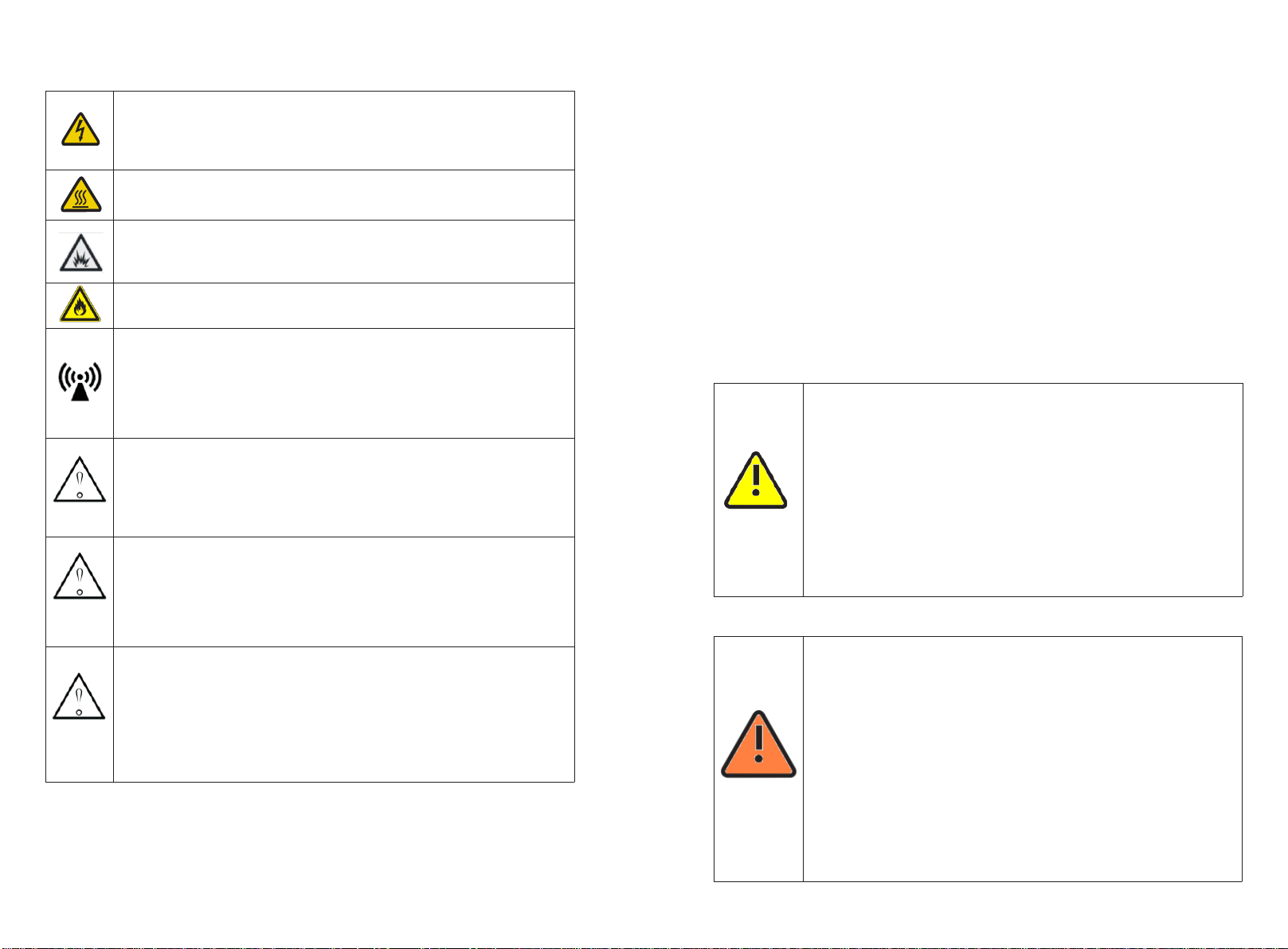
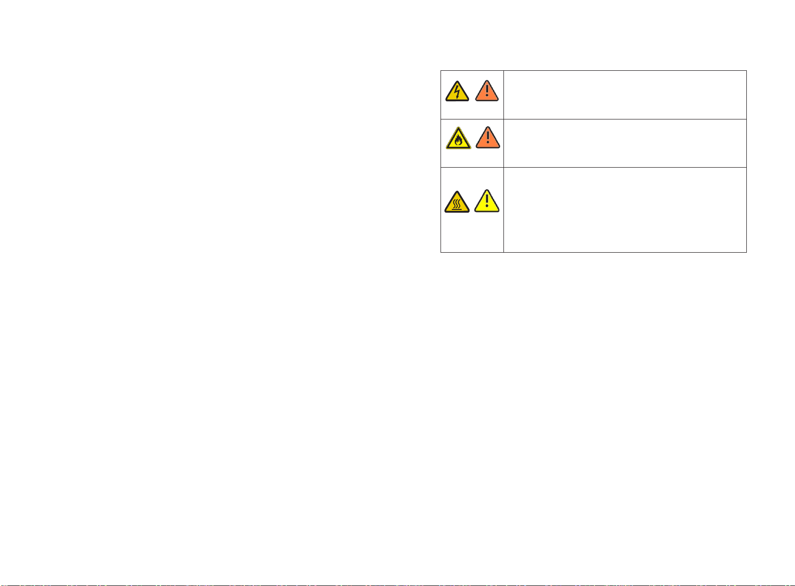
Danger to life due to lethal voltages!
Lethal voltages are present within the unit and on the power supply lines.
Therefore, only authorized electricians may install and open the unit. Even
when the unit is disconnected, high contact voltages may still be present
within the unit.
Danger of burn injuries due to hot enclosure parts!
During operation, the four sides of the enclosure lid and the heat sink may
become hot. Only touch the front enclosure lid during operation.
Electric arc hazards!
he product has large electrical potential differences between Its conductors.
Arc flashes can occur through air when high-voltage current flows. Do not
work on the product during operation.
Risk of fire!
Improper installation of the product may cause a fire.
Possible damage to health as a result of the effects of radiation!
In special cases, there may still be interference for the specified application
area despite maintaining standardized emission limit values (e.g. when
sensitive equipment is located at the setup locationor when the setup
location is near radio or television receivers).In this case, the operator is
obliged to take proper action to rectify the Situation. Do not stay closer than
8inch to the ARO-US for any length of time.
Grounding the PV generator!
Comply with the local requirements for grounding the PV modules and the
PV generator. Growatt recommends connecting the generator frame and
other electrically conductive surfaces in a manner which ensures continuous
conduction with ground these in order to have optimal protection of the
system and personnel.
Permanent connection!
The ARO-US may only be operated with a permanent connection to the
public power grid. The ARO-US is not intended for mobile use. Any other or
additional use is not considered the intended use.
The manufacturer/supplier is not liable for damage caused by such
unintended use. Damage caused by suchunintended use is at the sole risk of
the operator.
PV modules Capacitive Discharge Currents!
PV modules with large capacities relative to earth, such as thin-film PV
modules with cells on a metallic substrate, may only be used if their coupling
capacity does not exceed 1uF. During feed-in operation, a leakage current
flows from the cells to earth, the size of which depends on the manner in
which the PV modules are installed (e.g. foil on metal roof) and on the
weather (rain, snow). This "normal" leakage current may not exceed 50mA
due to the fact that the ARO-US would otherwise automatically disconnect
from the electricity grid as a protective measure.
NOTE
NOTE
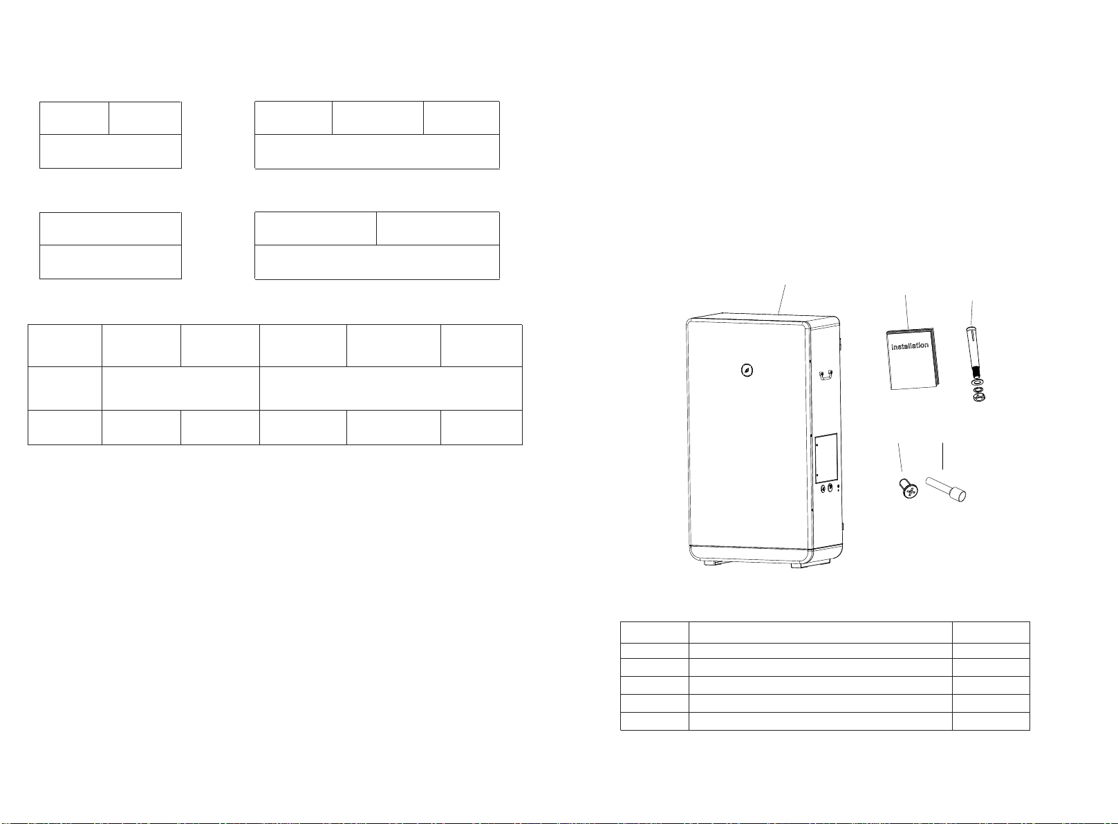
ARO-US
NOTE
ARO-US
2.4 Certified countries
With the appropriate settings, the unit will comply with the requirements specified in
the following standards and directives.
ØUl1973
Growatt can preset special grid parameters for other countries installation locations
according to customer requests after evaluation by Growatt. You can make later
modifications yourself by changing software parameters with respective
communication products. To change the grid-relevant parameters, an access code is
required; please contact Growatt support if needed.
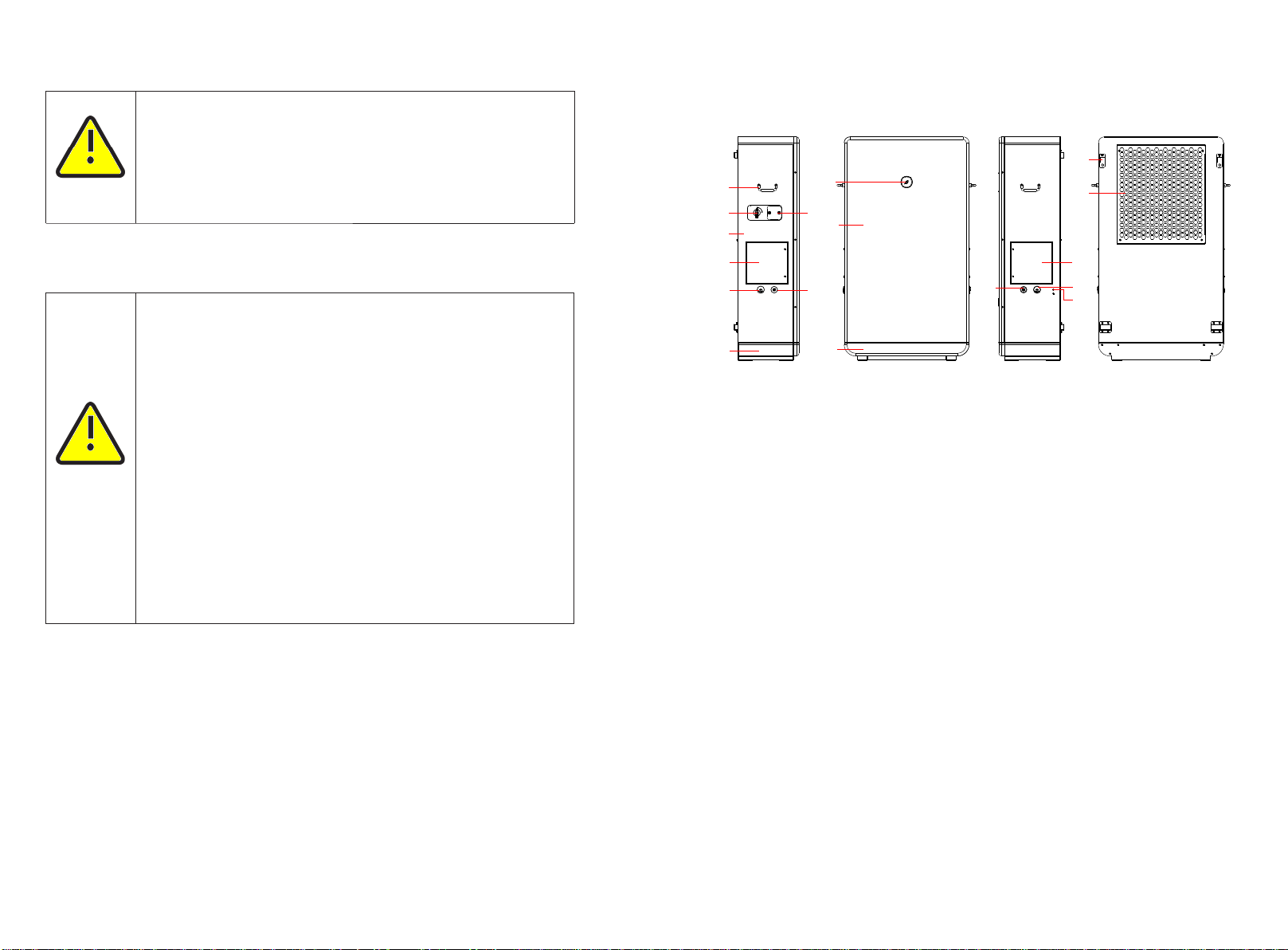
2.5 DC and AC disconnect
Isolate the ARO-US securely from the MIN TL XH-USusing DC Switch. DC and AC Switch shall
be able to disconnect all ungrounded conductors after installation.
2.5.1 Assembly Warnings
ØPrior to installation, inspect the unit to ensure absence of any
transport or handling damage, which could affect insulation
integrity or safety clearances; failure to do so could result in safety
hazards.
ØAssemble the ARO-US per the instructions in this manual. Use care
when choosing installation location and adhere to specified
cooling requirements.
ØUnauthorized removal of necessary protections, improper use,
incorrect installation and operation may lead to serious safety and
shock hazards and/or equipment damage.
ØIn order to minimize the potential of a shock hazard due to
hazardous voltages, cover the entire solar array with dark material
prior to connecting the array to any equipment.
WARNING
2.5.2 Electrical Connection Warnings
DANGER
ØThe components in the ARO-US are live. Touching live components
can result in serious injury or death.
lDo not open the ARO-US except the wire box by qualified persons.
lElectrical installation, repairs and conversions may only be carried
out by electrically qualified persons.
lDo not touch damaged ARO-US.
ØDanger to life due to high voltages in the ARO-US
lThere is residual voltage in the ARO-US. The ARO-US takes 20
minutes to discharge
lWait 20 minutes before you open the wire box.
ØPersons with limited physical or mental abilities may only work
with the Growatt ARO-US following proper instruction and under
constant supervision. Children are forbidden to play with the
Growatt ARO-US. Must keep the Growatt ARO-US away from
children.
6