Growatt GBLI Series User manual

0
6.5kWh Residential Energy Storage Battery Manual
Version: 1.1
Date: 2019-08-07

1
This document describes the application scenarios, installation, electrical connection,
commission and troubleshooting of 6.5kWh Residential Energy Storage Battery (hereinafter simply
put as battery). Before installing and operating battery, please ensure that you are familiar with
product features, functions, and safety precautions as provided in this document.
Warning and caution messages are listed in the document to remind users, installers and
maintainer of safe operation.
Symbol
Description
Indicates a potentially hazardous situation, if not avoided, could
result in serious injury or death.
Indicates a potentially hazardous situation, if not avoided, may
result in minor or moderate injury.

2
Table of Contents
1 Safety.............................................................................................................................................3
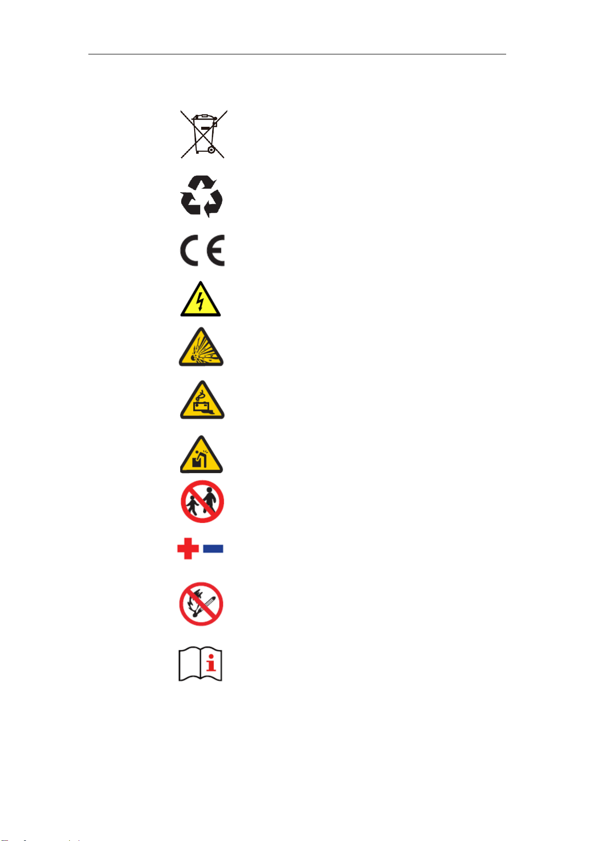
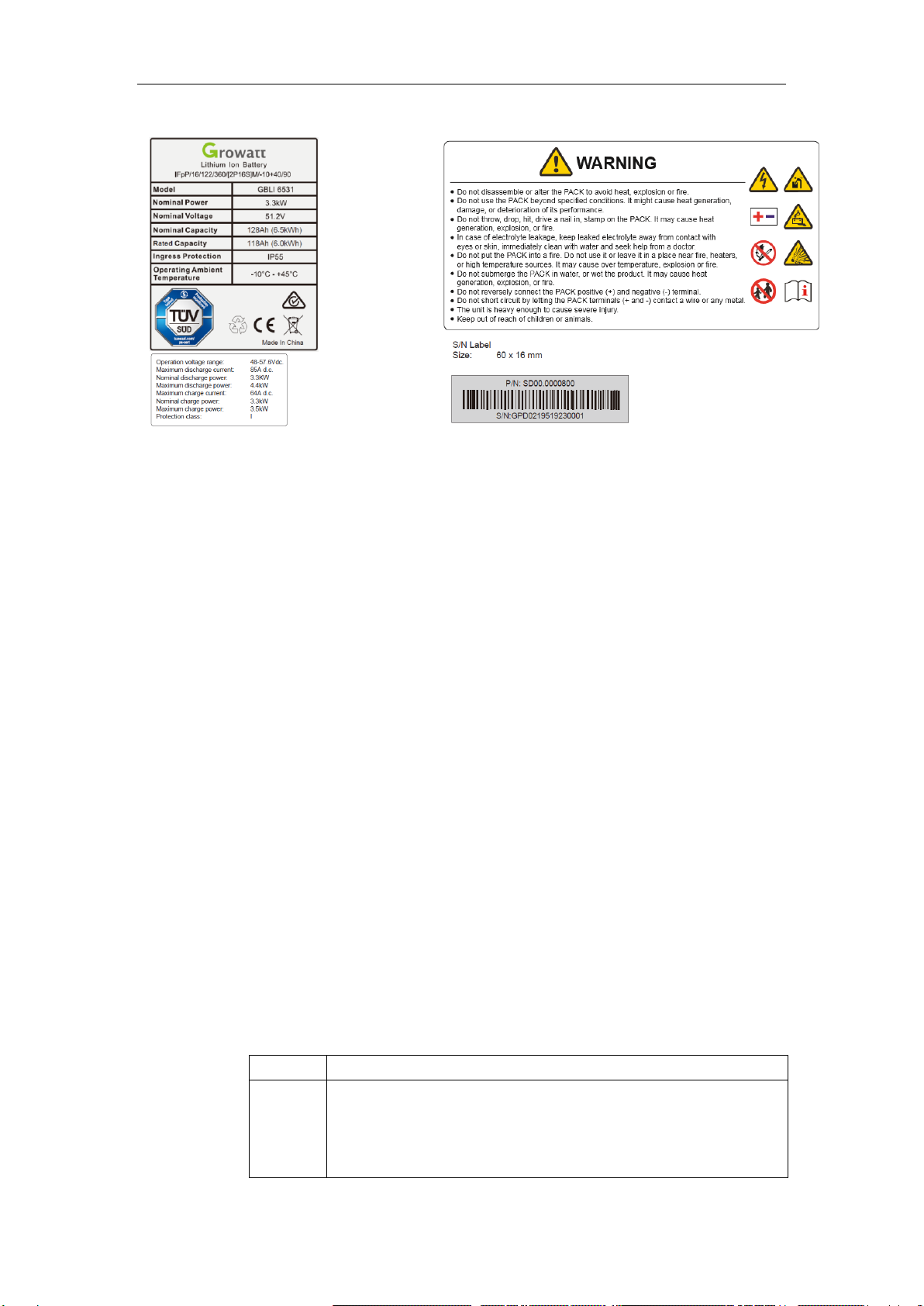
1.1 Warning Label.....................................................................................................................3
1.2 Precautions..........................................................................................................................4
1.3 Responses to Emergencies..................................................................................................4
1.4 Storage safety......................................................................................................................5
1.5 Transportation Safety..........................................................................................................5
2. Introduction to Product..............................................................................................................7
2.1 Intended Purpose.................................................................................................................7
2.2 Function ..............................................................................................................................7
2.3 Appearance..........................................................................................................................8
2.4 Technical Parameters...........................................................................................................9
3 Installation..................................................................................................................................10
3.1 Basic Installation Requirements........................................................................................10
3.2 Installation Required Tools ...............................................................................................11
3.3 installation Procedures......................................................................................................11
3.3.1 Wall Mounted Installation..............................................................................................12
3.3.2 Floor Standing Installation.............................................................................................14
4 Electrical Connection.................................................................................................................15
4.1 Preparation........................................................................................................................15
4.2 Electrical Connection Procedures......................................................................................15
5 Installation Steps under Parallel Connection..........................................................................17
6 Power on/off Battery..................................................................................................................19
6.1 LED Indication..................................................................................................................19
6.2 Power on Battery...............................................................................................................20
6.3 Power off Battery..............................................................................................................21
7 Maintenance ...............................................................................................................................22
7.1 Preparation........................................................................................................................22
7.2 Battery Replacement.........................................................................................................22
7.3 Firmware Upgrade ............................................................................................................22
7.4 Troubleshooting ................................................................................................................23

Safety
3
1 Safety
1.1 Warning Label
Do not dispose battery in household trash.
Recyclable.
Certification in European Union area.
Risk of electric shock.
Explosive gas.
Battery may leak corrosive electrolyte.
Battery is heavy enough to cause severe injury.
Keep battery away from children.
Do not reverse polarities.
Do not expose battery to flame.
Operate as specified by the manual.

Safety
4
Nameplate Label
1.2 Precautions
Risks of electrolyte leakage
Do not subject battery to strong impact.
Do not crush or puncture battery.
Do not open or mutilate batteries. Released electrolyte is harmful to the skin
and eyes.
Risks of fire
Do not expose battery to direct sunlight.
Avoid contact with conductive objects such as wires.
Keep battery away from fire source, inflammable, explosive and chemical
materials.
Do not dispose of batteries in a fire. The batteries may explode.
Risks of electric shock
Do not touch battery with wet hands.
Keep battery away from children and animals.
A battery can present a risk of electric shock and burns by high
short-circuited current.
Battery installation and wire connection must be operated by professionals.
Risks of damage
Keep distance to water source.
Do not subject battery to high voltage.
Place battery on a flat surface. Do not place any foreign object on top of
battery nor step on battery.
Battery-connected PCS should have reinforced insulation.
1.3 Responses to Emergencies
Event
Description and recommended actions
Leakage
Inhalation: leave the contaminated area right now.
Swallow: induce vomiting.
Contact with eyes: flush eyes with flowing water for 15 minutes.
Contact with skin: wash thoroughly with soap and water.

Safety
5
Immediately seek for medical intervention after taking emergency
measures.
Fire
Battery may catch fire when heated above 150℃. Please implement the
following actions:
1. Extinguish fire before the battery catches fire. ABC or carbon
dioxide extinguisher is recommended.
2. If the fire is too strong to put out, move battery to a safe place
before it catches fire.
3. If battery is on fire, evacuate people first before seeking help from
professional fire protection personnel.
4. If battery catches fire during charging, turn off the breaker
between battery and PCS when safety can be guaranteed.
Wet
battery
If battery became wet or has been submerged in water, do not access it.
Immediately contact your distributor for technical assistance.
Damage
Damaged battery is dangerous and must be handled with utmost care.
They are not usable for use and could pose a safety threat to people or
property. If battery is suspected to be damaged, stop any operation and
return it to distributor.
1.4 Storage safety
Place battery according to signs on packing case. Do not put battery upside
down or sidelong.
Store batteries in a place free from direct sunlight and rain.
Keep batteries at least two meters away from a heat source (such as a radiator).
Avoid contacting with corrosive and organic substances (including gas
exposure).
Batteries with deficiencies should be separated from normal batteries by setting
wall between or placing in difference fire protection zones.
Ambient temperature ranges between -30℃to 60℃during the first seven days,
and ranges between-20℃to 45℃within six months. Relative humidity ranges
between 5%RH-95%RH. Keep the storage area dry, clean and well ventilated.
In case of storage over six months, batteries should be recharged in the
following steps:
1. Identify batteries that need recharging;
2. Ensure batteries in power-off mode. Refer to Quick Guidance to complete
the installation and wire connection;
3. Set “CV=55V,CC=64A” and start recharging;
4. Recharge until LED2 flicks;
5. Leave circuit open and rest batteryfor five minutes. Check battery voltage.
If voltage is not less than 52 V, the recharging succeeds.
1.5 Transportation Safety
Battery has cleared UN38.3 (Section 38.3 of the sixth Revised Edition of the
Recommendations on the Transport of Dangerous Goods: Manual of Tests and Criteria) and

Safety
6
SN/T 0370.2-2009 (Part 2: Performance Test of the Rules for the Inspection of packaging for
Exporting Dangerous Goods). The battery is classified as class 9 dangerous goods, and is
subject to land and water transportation. It is mandatory to report to the airline company and
obtain approval before air transport.
Before transportation, press POWER button for two seconds and five LED
lights flicker for three times to power off battery.
During transportation, put battery flat, do not have battery stand or lean on
the floor to avoid possible crash.
Maintain temperature between -20℃to 45℃during the transportation.
Prohibit mixing up with explosive, inflammable or toxic objects.
Use van-type vehicle including container and metallic van-type vehicle.
Platform vehicle and convertible are prohibited.
Do not pile up foreign objects on the top of battery. Four batteries at most
can be piled up.
Maintain original packaging and keep labels complete and recognizable.
Prevent from direct sun exposure, rain, condensation and mechanical
damages.

Introduction to Product
7
2. Introduction to Product
2.1 Intended Purpose
The battery is a 6.5kWh LiFePO4 pack. It has a 48V battery module as the main power
supply unit which composed of 32 64Ah cells in two parallel and sixteen serial connect
(2P16S). Battery coordinates with PV, PCS, Grid and loads in the residential energy storage
system. The four typical application scenarios are as shown below:
2.2 Function
Compared with normal batteries, the battery is characterized with better charging and
discharging performance, longer cycle life and less self-discharging loss. The build-in BMS
can monitor battery operation status and alarm timely to avoid operation out of limit. Two
batteries can be parallel-connected to expand energy and power of energy storage system.
Battery realizes communication with PCS via CAN network port.
The energy produced by PV is
optimized to supply loads. The excess
energy is used to charge battery, then
export to grid.
Battery powers loads at nighttime when
there is no PV. If battery energy is
insufficient, it can supply loads together
with grid.
When grid falls, battery and PV can
power loads.
Battery can be charged by grid. Users are
suggested to store energy from grid to battery
when electricity price is relatively lower.

Introduction to Product
8
Monitoring: detect the voltage and temperature of cell, the voltage and current of battery.
SOC estimate: indicate the precise volume of remaining electricity.
Alarm: alarm when overvoltage, under voltage, overcurrent, over temperature or under
temperature occurs.
Protection: protect against over voltage, under voltage, over current, over temperature,
under temperature, cell fault and hardware failure.
Report: report alarm messages and operation data to PCS via CAN and RS485 network
ports.
Parallel connection: support a maximum of two batteries in parallel connection.
Power-off triggered by fault: battery powers off if level three under voltage, 0V cell or
parallel connection failure happens.
Forced power-off: when battery does not connect to mains supply, press POWER button for
two seconds and battery powers off.
Activation: input 45V~60Vvia P+/P- terminals, battery will be activated from off mode to
standby status.
2.3Appearance
The battery is an energy storage unit composed of cells, mechanical parts, battery
management system (BMS) as well as power and signal terminals. Product dimension (unit:
mm) and appearance are as shown below:
No.
label
Name
No.
Name
Function
1
POWER
POWER button
8
LED4
81%-100%SOC indication
2
COM1
Network port 1
9
LED3
61%-80%SOC indication
3
COM2
Network port 2
10
LED2
41%-60%SOC indication
4
-
Negative terminal
11
LED1
0%-40%SOC indication
5
+
Positive terminal
12
Safety
vent
A vent to release pressure
inside.
6
Grounding terminal
7
RUN/A
LM
Blue RUN light indicates normal operation.
Red ALM light indicates failure or protection status.

Introduction to Product
9
2.4 Technical Parameters
No.
Item
Specification
1
Nominal capacity/energy
128Ah/6.5kWh
Rated/usable capacity/energy
118Ah/6.0kWh
2
Typical voltage
51.2 V
Operating voltage
48V ~57.6V
3
Standard charging current
(25℃)
64A
Max. discharging current
(25℃,3s)
96A
Continual Max. discharging
current (25℃)——85A
85A
4
Rated discharging power
3.3kW
Max. discharging power
4.4kW
Peak discharging power
5kW/3S
Rated charging power
3.3 kW
Max. charging power
3.5 kW
5
Max. Short circuit current peak
2000A
6
Operating temperature range
-10℃~45℃
Optimal operating temperature
0℃~30℃
7
Storage conditions
Within 6 month after initial charge
temperature: -20℃~ +45℃
humidity: 5% RH -95%RH
8
Room temperature cycle
life(25°C)
≥6000 cycles/60%EOL
9
Cooling
Natural cooling
10
Dimension
W475*D133*H745 mm
11
Weight
58kg±1Kg
12
Installation
Wall-mounted installation/floor
standing installation
13
Ingress protection
IP55
14
Cell safety certification
IEC62619/UL1973
15
Battery safety certification
IEC62619/CE/RCM/UL1973/CEC
16
Transportation test standard
UN38.3+PI965(sea)
17
Network port
CAN2.0B*1CH; RS485*1CH
18
Maximum parallel-connected
batteries
Two batteries
19
Protective class
I
20
over voltage category
II
21
External bipoles circuit
breaker required for battery
output
80V, 100A, 2P

Installation
10
3 Installation
3.1 Basic Installation Requirements
Battery can be installed indoors or outdoors. Ensure the following conditions
are satisfied:
A deviation of -5o≤Ө≤5ois allowed for both installation against wall and floor.
Additionally, the distance between the bottom part of battery and floor should
not exceed 500mm. Please refer to figures below (√ means acceptable
installation and X unacceptable).
Do not place the battery upside down nor keep it flat as above.
Build sunshade & rain shelter to avoid direct exposure to sunlight and rain.

Installation
11
Keep the dirt or dust at a minimal level;
Do not install battery in a place where flood frequently occurs;
Do not install battery in highly humid area such as bathroom;
Ensure direct contact between battery shell and ambient air. Do
not cover or shield battery to avoid poor cooling.
3.2 Installation Required Tools
The following tools are required to install battery:
Drill
Crimper
Wire stripper
Screw driver
Cable wrench
Pencil
Tape measure
Multi-meter
Hydraulic plier
Insulated gloves
Safety goggle
Safety shoes
3.3 installation Procedures
Pre-installation Check
Check exterior package: before opening package, check for damages like holes, cracks or other
traces on exterior packing case. If any abnormity is detected, do not open
the package and contact your distributor.
Check deliverables: after opening package, check if deliverables are complete. If there is any
part missing or damaged, please contact your distributor.
Check and confirm the battery is powered off and breaker is open before any further step.
Accessory list:
Note: External bipoles circuit breaker required for battery output. An external bipoles dc
isolator is required.

Installation
12
StandardAccessories
Single battery
Parallel-connected batteries
Battery
1 PCS
2PCS
Terminal
Positive terminal 1PCS (Min. 3 AWG)
Negative terminal 1PCS (Min. 3AWG)
Network terminal 1PCS(Min. 26 AWG)
M6-OT 1PCS
M6 nut 1PCS
Positive terminal 2PCS (Min. 3 AWG)
Negative terminal 2PCS (Min. 3AWG)
Network terminal 3PCS(Min. 26 AWG)
M6-OT 2PCS
M6 nut 2PCS
Fastening
M8 expansion screw 2PCS
M8*H60 anchor bolt 2PCS
M8 expansion screw 4PCS
M8*H60 anchor bolt 4PCS
Manual
1 PCS
1 PCS
Warranty
card
1 PCS
1 PCS
Optional Accessories
Single battery
Parallel-connected batteries
Fastening
M8 expansion screw 2PCS
M8*H60 anchor bolt 2PCS
Gradienter 1PCS
M8 expansion screw 4PCS
M8*H60 anchor bolt 4PCS
Gradienter 1PCS
Bus bar
box
1PCS
Bracket
1PCS
2PCS
3.3.1 Wall Mounted Installation
The weight capacity of wall should exceed 4 times
weight of battery.
Keep the distance between bracket, wall and floor
as is shown (320mm, 320mm, 765mm).
Step 1 Confirm installation spot.
At least two persons participate the installation. One
person places the bracket on wall and ensure the
gradienter horizontal; the other person marks four spots
of screw driving.After confirming the spots to drive
screws, put down the bracket.

Installation
13
Step 2 Fix bracket to wall.
Choose alloy drill bit with a diameter of 12mm
and install it to a drill. Drill in the four spots that
have been located in step 1 and have at least
60mm drilling depth. Clean the soil and drive
expansion tube into the hole. One person puts the
bracket on wall and minds to keep gradienter
horizontal. The other person drives M8 screw
through the bracket into hole.
Step 3 Fix battery on bracket.
Rotate the left latch leftward and the
right latch rightward until they keep
perpendicular to the battery. Install
battery from the top down and lock the
connection part of battery with the
support plate of bracket.
Step 4 Insert power cable and network cable into
battery terminals.
Having confirmed fixed installation, plug
power cables into battery terminals (orange
positive terminaland black negative terminal).
Plug CAN network cable into the network
ports of PCS and battery. Please refer to
Section 4.2 for network making details.
Rotate the left latch rightward until the notch locks
limiting pin, rotate the right latch leftward until the
notch locks limiting pin too.
Leave a minimum clearance of 133mm before the front surface of battery.
In order to guarantee a stable connection between battery and bracket,
please visually check if the two upper joints are fixed. Try to move the
lower part of battery away from wall. The connection is proved qualified
if the battery cannot be moved at all. Otherwise, please connect the
battery and bracket again until confirming a fixed connection.

Installation
14
3.3.2 Floor Standing Installation
Step 1 Confirm installation spot.
Place batteryin the to-be installed area. Rotate the left latch
leftward and the right latch rightward until they are
perpendicular to the battery. Keep the distance between
wall and battery as shown (300mm, 300mm). Leave a
minimum clearance of 133mm before the front surface of
battery. Use pencil to mark where the notches of two
latches are and confirm the two drilling spots. Move
battery away.
Choose an alloy drill bit with a diameter of 12mm and install
it in the drill. Drill two holes in the spots that have been
confirmed in step 1. Keep the drilling depth as least 60mm.
Clean the soil and drive expansion tube into hole.
Step 3 Insert power cables and network cable
into battery terminals.
Check and confirm battery is well fixed
to wall. Plug the power cables into
battery terminals. Plug the CAN
network cable into network ports of
battery and PCS. Please refer to Section
4.2 for cable making details.
Step 2 Install battery.
Move battery back to the place confirmed in step 1.
Drive M8 screw through notch of latch into wall.

Electrical Connection
15
4 Electrical Connection
4.1 Preparation
4.2 Electrical Connection Procedures
Item
No.
Definition
COM1/
COM2
1
RS485B
2
RS485A
3
GND2
4
CANH
5
CAHL
6
GND2
7
WAKE-
8
WAKE+
Step 1 Connect grounding cable.
It is recommended to fasten grounding terminal
and grounding cable with M6 screw.
Step 2 Make power cables.
1. Strip cable sheaths for 20±0.5mm, with
orange positive cable and black negative
cable. Insert sealing, sealing nut and
protection cover along the cable as
shown.
2. Insert the copper wires all into the
joint sleeve.
4. Pull protection cover and
have connected terminal inside.
3. Press connecting part with a
hydraulic clamp; tighten up sealing,
sealing nut and joint sleeve.
Note: when uninstalling
battery, operator should
use a screwdriver to
pull up the marked spot
as shown.

Electrical Connection
16
Step 3 Make network cables.
1. Strip cable sheaths for 15±0.5mm first.
Insert sealing and sealing nut along the
cable.
2. Network cable adopts standard 8-core
cable. Reserve two wires, cut the other
six wires.
Make CAN network cable: insert the two
remaining wires into pin 4 and pin 5 of RJ45
plug. Ensure the two wires stay aligned and
keep consistent between wire color and pin.
Make RS485 network cable: insert the two
remaining wires into pin 1 and pin 2 of RJ45
plug. Ensure the two wires stay aligned and
keep consistent between wire color and pin.
3. Crimp the RJ45 plug with a wire crimper.
4. Connect RJ45 plug with joint sleeve, and
tighten up sealing, sealing nut and joint
sleeve.
Step 4 Insert power cables and network cable into battery terminals.
1. Measure battery voltage with a multi-meter and ensure the voltage output is 0V under power-off mode.
2. Plug one end of the power cables that have been made in Section 4.2 step 2 into DC breaker, and plug the
other end into the battery terminals.
3. Plug the CAN network cable that has been made in Section 4.2 step 3 into a network terminal of battery
(CMO1 or COM2), and plug the other end of CAN network cable into network port of PCS.

Installation Steps under Parallel Connection
17
5 Installation Steps under Parallel Connection
If voltage difference is measured more than 1V, the difference shall be adjusted to be less
than 1V either by charging the battery with lower voltage or discharging the battery with
higher voltage before conducting the parallel-connected installation.
Step 1 Install battery.
Power on two batteries in condition of no
load, measure their voltages with a
multi-meter and confirm the voltage
difference not more than 1V. After that, power
off two batteries and install them according to
the procedures specified in Section 3.3. Keep
the minimal distance between two batteries,
wall and battery, bus bar box and wall as
shown (unit: mm)
Step 2 Insert power cables into battery terminals.
Make the power cables of both batteries
based on Section 4.2 Step 2. Plug one end of
positive and negative terminals into DC
breaker. Respectively measure the positive
and negative terminal blocks of two batteries
with a multi-meter, and ensure the voltage
outputs under off mode are both 0V. After
that, plug the other end of power cables into
terminals on two batteries.
Step 3 Insert network cables into battery terminals.
Make RS485 and CAN network cables based
on Section 4.2 step 3. Connect two batteries
with the RS485 network cable, and connect
battery and PCS with the CAN network
cable. Specifically, Plug RS485 network
cable into one network port of each battery,
plug one end of CAN network cable into the
CAN network port of any battery, and plug
the other end into PCS network port.

Installation Steps under Parallel Connection
18
RS485 network cable only applies to the communication between two batteries, and CAN
network cable only applies to the communication between battery and PCS.
Ensure two batteries in parallel connection are from the same batch, same model and same
manufacturer. Do not mix an old battery with a new battery. Batteries undergone less than
300 cycles are defined as new batteries.

Power on/off Battery
19
6 Power on/off Battery
There are many technical contents involved in the electrification process, and technicians must go
through technical training and obtain certificates in compliance with local laws and regulations.
Please stand on dry insulating objects and do not wear metal objects such as watches, rings and
necklaces during operation. Insulating tools should be used.
Do not contact with two charged positions with a potential difference.
If other people are not allowed to operate, the prohibition sign should be hung on the distribution
equipment: "No closing, someone operating."
Make sure to turn off breaker before checking battery.
Measure battery voltage with a multi-meter and ensure voltage output under off mode is 0V.
If any abnormality is detected when powering on, immediately power off the battery. Proceed again
only after causes are confirmed.
6.1 LED Indication
LED light definition
Status
SOC
SOC indication
RUN/ALM
(green and
red lights)
Remark
LED1
LED2
LED3
LED4
LED5
charging
0%-25%
■(T=1s)
●
RUN light on and SOC lights flicker
26%-50%
■(T=2s)
■(T=1s)
●
51%-75%
■(T=3s)
■(T=2s)
■(T=1s)
●
76%-99%
■(T=4s)
■(T=3s)
■(T=2s)
■(T=1s)
●
100%
●
●
●
●
●
Discharging
100%-81%
●
●
●
●
●
80%-61%
●
●
●
●
60%-41%
●
●
●
40%-14%
●
●
13%-0%
●
★
LED1 flickers
Idle
0%-13%
●
★
LED1 flickers
14%-40%
●
●
41%-60%
●
●
●
61%-80%
●
●
●
●
81%-100%
●
●
●
●
●
Parallel
connection
Parallel
connection
succeeds
SOC indicates current remaining capacity
★
RUN light flickers for five times
when parallel connection succeeds.
Note: ★(ALM light flickers)●(ALM light remains on)
●(RUN light remains on)★(RUN light flickers)
This manual suits for next models
1
Table of contents
Other Growatt Camera Accessories manuals

Growatt
Growatt GBLI6531 User manual

Growatt
Growatt Hope 4.8L-C1 User manual

Growatt
Growatt ARK 2.5L-A1 User manual

Growatt
Growatt US2000 User manual

Growatt
Growatt ARO 6.6H-C1-US Series User manual

Growatt
Growatt AXE 5.0L Operating and maintenance instructions

Growatt
Growatt ARK 2.5L-A1 Operating and maintenance instructions

Growatt
Growatt AXE 5.0L User manual

Growatt
Growatt ARK 5.1-25.6XH-A1 User manual

Growatt
Growatt GBLI 6532 User manual