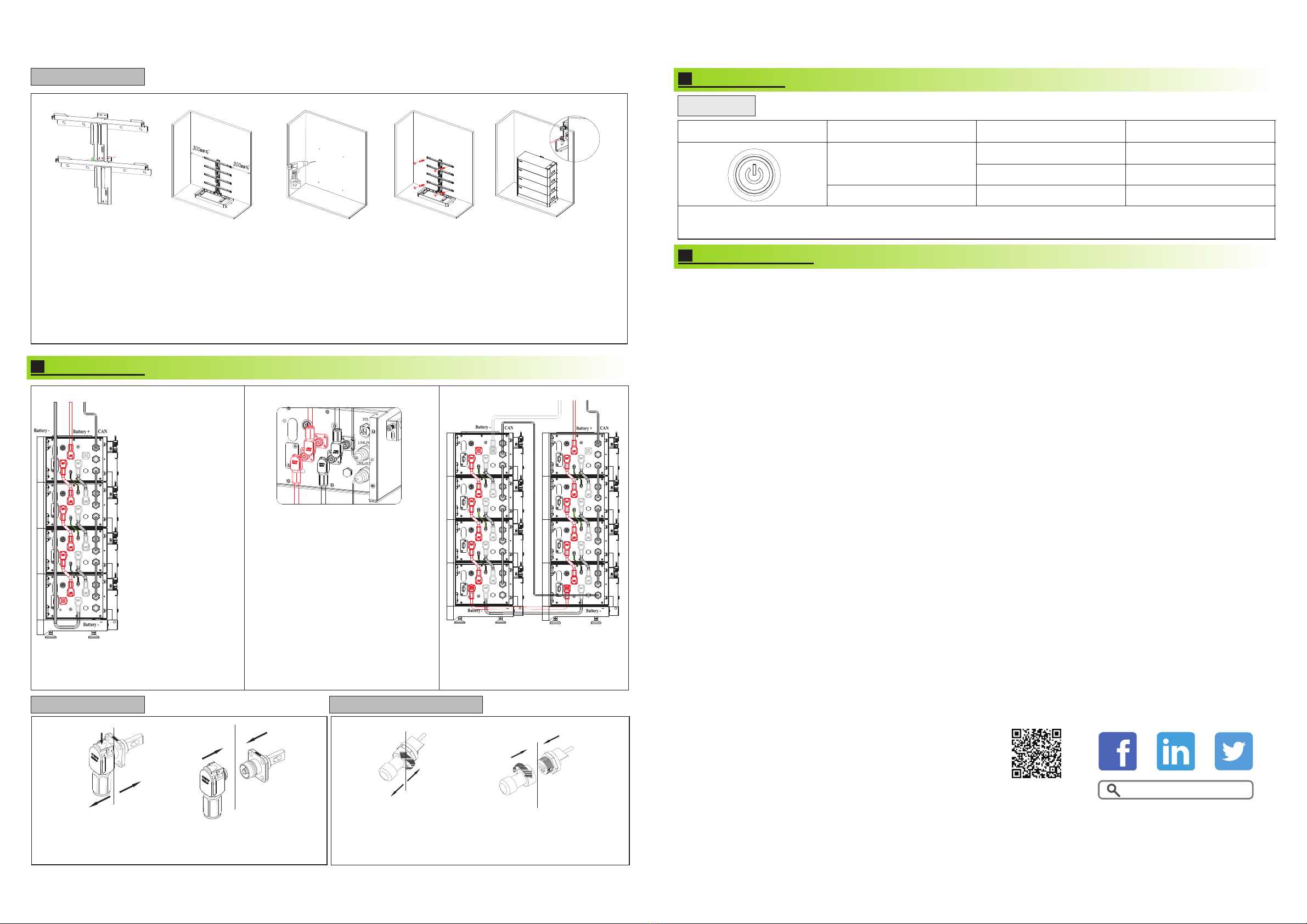
Note: When multiple battery modules are used in parallel connection, you only need to press one key of any module to start the system,
and also press one of the keys to shut down the battery system.
6.
Shenzhen Growatt New Energy Co., Ltd.
2F and 3F,Building 4,Jiayu Company Industrial Park,Xibianling,
Shangyu Village,Shiyan Street,Bao'an District,Shenzhen
+86 0755 2747 1942
www.ginverter.com
T
E service@ginverter.com
W
Download
Manual Growatt New Energy
GR-UM-205-A-00GR-UM-205-A-00
5.1 Power button
3.2.Installation procedure
1. Assemble the wall hangers together with M6 flange nut.
2.Place the mounting base where you want the battery to be mounted.
3.Place the wall hangers on the wall and match the base.
4.Mark the holes that need to be punched; Noted that only two ends of the top wall hanger and the bottom wall hanger need to be marked.
5.Remove the wall hangings and the base and drill a hole with a depth of 55mm at the mark with a drill of φ8.
6.Expand the bolt with a hammer into the hole in the wall, place the wall hangers and based, install the nut(including elastic flat pad)and
tighten the nut with a wrench.
7.Hang the ARK2.5L-A1 on the wall hangers.
8.Adjust the battery level with M6 external hexagon torque wrench.
9.Install the safety screws(M4x10 Combination screw) on both sides of top module.
Fig 6 Multiple ARK2.5L-A1 with base installation process
4.
5.
Electrical wiring
Key operation
4.1.Power line connection 4.2.Communication line connection
TO PCS
Wire
harness
side
Battery side
Wire
harness
side
Press Battery side Battery side
Communication
harness side
Battery side
Communication
harness side
Fig 8 Schematic diagram of power and
communication wiring harness connections
Fig 7 Parallel connection of four batteries
Fig 11 Disconnect power
terminals
Fig 10 Connect power
terminals
Fig 12 Connect Communication
terminal
Fig 13 Disconnect Communication
terminal
The parallel communication connection is from the LINK-OUT port
of the top module to the LINK-IN port of the next module shown in
Fig 7.
Press the position indicated in the figure above before discon-
necting the power terminal.
Service and contact
Note:
The battery is not allowed
to be installed in the runni-
ng state,and all the RUN
lights of battery modules
s h o u l d b e o f f b e f o r e
installation.
To ensure system security,
do not forget to install
ground wire.
For the power lines conne-
cted to PCS, the positive
power line is drawn from
the top battery module,
and the negative power
line is drawn from the
bottom battery module .
The switch connect PCS
to ARK 2.5L-A1,we recom-
mend the use of molded
case circuit breaker with
r a t e d w o r king v olta g e
greater than 500V and
r a t e d w o r k i n g cu r r e n t
greater than 125A.
To PCS
Fig 9: stacked
in two line
parallel connection
1.Before connecting the power wiring
harness, please pay attention to the
positive and negative terminals, the red
terminals are connected to the positive
terminals and the black terminals to the
negative terminals.
2.The PCS communication terminal is
used to communicate to the PCS. Link-in
terminals are used for signal inlet of
multiple parallel battery modules. Link-out
terminals are used for signal output of
multiple parallel battery modules. When stacked in two lines,you need to buy
the accessory of wires connecting two
stacks of battery systems. The connection
mode is shown in the fig 9.


