Growatt Hope 4.8L-C1 User manual

SHENZHEN GROWATT NEW ENERGY CO.,LTD
Hope 4.8L-C1 Lithium Iron Phosphate Battery
Residential Energy Storage System
Quick Guidance
Date: 2021-04-29

Read this Guidance carefully before installation to understand product features and
safety precautions.
!
WARNING
* Operators should be well trained to fully understand grid-connected photovoltaic power system and
national/regional standards.
* Installers must use insulating tools and wear safety equipment.
* Device damages caused by noncompliance with storage, transportation, installation and usage
requirements specied in Quick Guidance and Manual are not covered by Warranty.

1
1 Important Safety Information
Risks of electrolyte leakage
⁎Do not subject battery to strong impact.
⁎Do not crush or puncture battery.
⁎Prevent battery from falling. In case of fall, turn o the battery immediately and stop using it.
⁎Do not open or mutilate batteries. Released electrolyte is harmful to the skin and eyes.
Risks of re
⁎Do not expose battery to direct sunlight.
⁎Avoid contact with conductive objects such as wires.
⁎Keep battery away from re source, inammable, explosive and chemical materials.
⁎Do not dispose of batteries in a re.
Risks of electric shock
⁎Do not touch battery with wet hands.
⁎Keep battery away from children and animals.
⁎A battery can present a risk of electric shock and burns by high short-circuited current.
⁎Battery installation and wire connection must be operated by professionals.
Risks of damage
⁎Keep a distance to water source.
⁎Do not subject battery to high voltage.
⁎Place battery on a at surface. Do not place any foreign object on top of battery nor step on battery.
⁎Battery-connected power supply should have reinforced insulation.

2
2 Product Appearance
The battery is an energy storage unit composed of cells, mechanical parts, battery management system
(BMS) as well as power and signal terminals.
Table 2-1 Mechanical features
Parameter Value
Dimensions W442*D479*H128 mm (excluding brackets and terminals)
Weight ≤ 45 kg
Installation Rack-mounted installation/Stackable installation with brackets
Table 2-2 Ports and terminals
No. Label Name
1PCS PCS communication port
2Link-Out Network port for parallel connection
3Link-In Network port for parallel connection
4 DO1 DO2 Two-channel dry contact port
5SOC Display the battery capacity, and each indicator represents 25% SOC
6 ALM Display the alarm status of the battery
7 RUN Display the running status of the battery
8Power Power ON/OFF button
9+/- Positive and negative power terminals
10 Grounding terminal
11 Rack mount bracket 19-inch rack mount bracket, adjustable
12 Handle Fold-able handle
442
±
1.5
479 2
491
508.5 2
128
±
1.5
±
±
482.6
1 2 3 4 5 678 9 10
11
12

3
3 Package Items
Before installation, check carefully for any damages on the package and the products and inspect if all
accessories in the list are included. If any part is missing or damaged, please contact your distributor.
Battery Package Hope 4.8L-C1 Kit package
Item NO. Part Name Quantity Item NO. Part Name Quantity
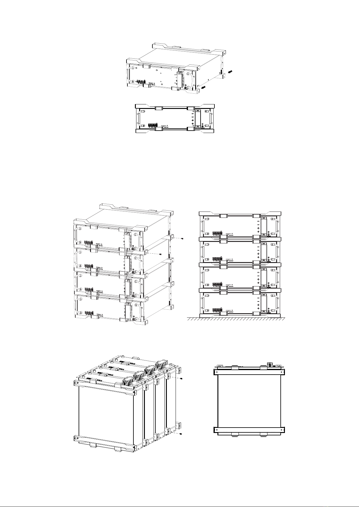
1Hope 4.8L-C1 Battery 1pcs 5Battery Bracket 4pcs
2 Crystal plug 2pcs 6 Screw bolt 4pcs
3Quick Guidance 1pcs 7 RNB-22-6 lug 4pcs
4Warranty Card 1pcs 8 Screw 4pcs
9Power+ Cable 1pcs
10 Power- Cable 1pcs
11 Network Cable A 1pcs
12 Network Cable B 1pcs
Warranty Card
To make a fault claim, please fully read and clarify warranty terms in advance. Then ask onsite engineer to fill the
information required in this card, sign and send back to Growatt or its authorized distributor.
1. Distributor name:
2. Battery system location:
3. Battery serial number:
4. Date of fault happened:
5. Fault description:
Cannot be turned on No communication Cannotbe charged
Cannot discharge ALM on Others
6. Inverter brand and model:
7. Real-time battery information shown on inverter or inverter monitor system APP:
Voltage: V;Current: A;SOC: %;Temperature: ℃
8. How long has the system been used?
Dead on arrival
Under 6 months 6 monthsto 1 year 1 year to 3 years
More than 3 years
9. When did the fault happen?
Morning Afternoon Nightfall
Midnight Other time
10. How often did the fault happen?
Once or twice Threetimes or more Everyda y
Other
11. If the customer can see the battery,please check the LED light status:
RUN (Blue or Green)
ALM (Red)
SOC lights (Blue or Green)
On
Off
Flickering
12. Battery power terminal voltage measured by multi-meter:
13. Please attach all necessary photos or videos, for instance, battery SN label and LED light as evidence to the fault
claim.
Pleaseattach all the information required above and send back to Growatt or the authorized distributor. Fail to submit
any required information may lead to a lack of information to process the claim.
Service Manager: Date:
SHENZHEN GROWATTNEW ENERGY CO.,LTD.
T:+86 0755 2747 1942
W: www.ginverter.com
Address: 2nd&3rd Floor, Building 4, Jiayu Industrial Zone, Xibianling, Shangwu
Village,Shiyan, B aoanDistrict, Shenzhen, P.R.China
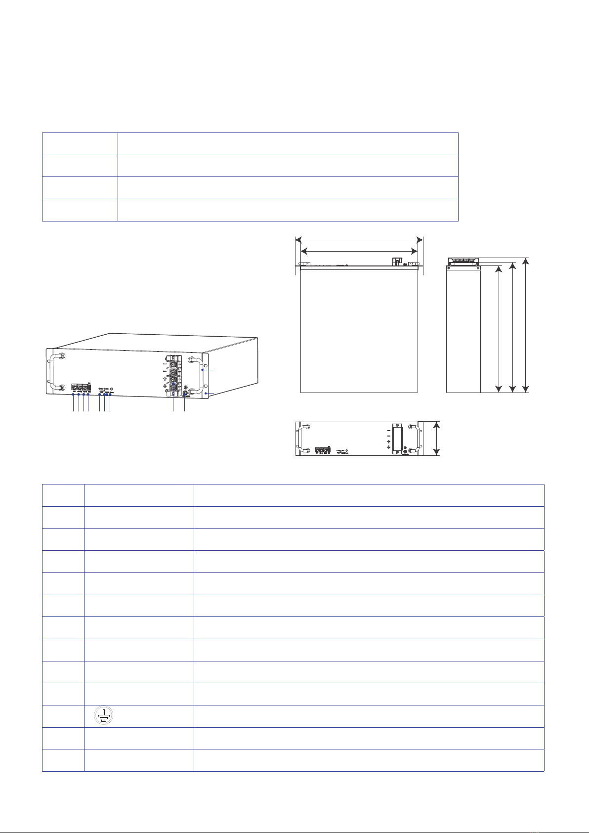
1 2 3 4
56 7 8 9 10 11 12

4
4 Tools and Protective Equipment
Heat gun Cross-head screwdriver Wire cutter
Wire stripper Hydraulic plier Tape measure
FUSED
FUSED
1000VMAX
10A 100mA COM
VΩ
OFF
V
A
A
V
Ω
Hz
%
Multi-meter
Insulated gloves Safety goggles Rubber boots
To prevent injury, always wear acid-resistant clothing, PVC gloves, goggles and rubber boots during
installation and operation.

5
5 Installation of Battery
It is recommended to install the battery into a cabinet and place it indoor. If you install it outdoor, select a
cabinet with a sucient IP rating. Build sunshade & rain shelter to avoid direct exposure to sunlight and
rain for outdoor application.
!CAUTION
⁎Do NOT expose battery into sunshine or rain directly.
⁎Keep the dirt or dust at a minimal level.
⁎ Do not install battery in a place where ood frequently occurs.
⁎Do not install battery in highly humid area.
⁎Ensure direct contact between battery shell and ambient air and do NOT cover or shield battery.
5.1 Battery Orientation
The battery supports stackable installation with brackets. At most 8 batteries can be athwart stacked.
Ensure that you install the battery in correct directions. Please refer to gures below (√ means acceptable
and X unacceptable).
5.2 Stackable Installation with Bracket Support
!CAUTION
Before installing battery, remove conductive ornaments such as watch, bracelet, and rings and wear protection
equipment.
Check and conrm the battery is powered o and battery breakers are turned o before any process.
Step 1 Prepare support brackets.

6
Step 2 Set the battery into 2 pcs of brackets from the rear.
Step 3 Stack battery packs with brackets and fasten screws.
At most 8 battery packs can be stacked in this way.
...
Max. 8 PACKs
The battery stack can be placed in standing position or panel upward.

7
6 Electrical Connection
The battery provides three network ports and four power terminals for electrical connection.
Terminals/Ports Type Cable Cross-Section Current Carrying Capacity
Grounding M6 16mm²
+/- M6 25mm² or 3AWG 100A
PCS/Link-In/Link-Out RJ45 24AWGX8
6.1 Prepare Cables
Before connecting the batteries, you need to prepare grounding wire with OT lugs to meet the
requirements of your applications.
!CAUTION
Cables can be made by yourself or purchased from qualied providers.
It is recommended to purchase nished power wire products according to the terminal specications of the battery.
If you make cables on your own, please ensure that the terminals are crimped properly.
Make grounding wires with OT terminals.
Step 1 Strip cable sheaths and put a piece of heat shrinking tube
along the wire. Grounding: 16 mm²
Step 2 Insert conductive wires into an OT terminal.
M6
Step 3 Crimp the OT terminal with a hydraulic plier.

8
Step 4 Use a heat gun to heat the heat shrinking tube.
6.2 Connect One Battery
!CAUTION
⁎ Ensure that battery is in o mode and battery breaker is turned o.
⁎Ensure that no cable is twisted after battery is wired.
After making the cables ready and equipping yourself with protective devices, connect cables to the
battery in the following way:
Step 1 Use an M6 screw to fasten the grounding wire to grounding terminal and x the other end to the
inverter directly.
Note that the cross-section of grounding wire is 16mm2.
Cross-head screwdriver
Step 2 Insert a network cable into battery port.
1. Plug one end of network cable A into the PCS port of battery, and plug the other end into the network
port of the inverter.
2. Insert two terminators (a crystal plug with pin 4 and pin 5 short circuited) into Link-Out and Link-In
respectively.

9
Terminator
Network cable A
Step 3 Connect power wires.
1. Fix the OT terminals of power wires to one pair of the +/- terminals of the battery.
2. Put back the plastic cover.
3. Fix the other ends to a breaker and then connect to the inverter.
!CAUTION
⁎ When connecting a power wire, ensure that its OT terminal is placed in the correct direction.
⁎ Do NOT stack two OT terminals onto one power interface.

10
Inverter
6.3 Connect Batteries in Parallel
!CAUTION
⁎ Ensure that all batteries are in o mode and battery breakers are turned o.
⁎Ensure that no cable is twisted after batteries are wired.
⁎ The batteries shall be manufactured within one year and have a cycle dierence less than 300.
Step 1 Conrm that the voltage dierence is not greater than 1V.
1. Power on the batteries without load and use a multi-meter to measure their voltages.
2. If the voltage dierence is greater than 1V, charge the battery with lower voltage.
3. Power o the batteries.
Step 2 Connect network cables.
1. Insert one end of network cable A into the PCS port of Battery 1 and the other end into the network
port of the inverter.
2. Insert a terminator (a crystal plug with pin 4 and pin 5 short circuited) into Link-In of Battery 1.
3. Use network cable B to connect the Link-Out port of Battery 1 and the Link-In port of Battery 2.
Connect the rest batteries in a similar way till the last one is connected.
4. Insert a terminator (a crystal plug with pin 4 and pin 5 short circuited) into Link-Out of Battery 4.

11
Battery 1
Battery 2
Battery 4
Inverter
Battery 3
Step 3 Connect grounding wires.
Connect the grounding terminal of each battery to the grounding bar.
Inverter
Battery 1
Battery 2
Battery 4
Battery 3
Grounding bar

12
Step 4 Connect power wires.
Connect the +/– terminals of each battery to the +/- of the junction box respectively and then connect
the junction box to the inverter.
Inverter
Grounding bar
Junction box

13
7 Operation and Commissioning
After the battery is installed and wired, operate and commission it to check if the battery works properly.
!CAUTION
When operating or commissioning the battery, please strictly follow the safety instruction below:
⁎Technicians must go through technical training and obtain certificates in compliance with local laws and
regulations.
⁎Please stand on dry insulating objects and do not wear metal objects such as watches, rings and necklaces
during operation.
⁎Use insulating tools and wear protective devices.
⁎ Do not contact with two charged positions with a potential dierence.
⁎ Hang a prohibition sign that stops people from turning on the breakers on the power distribution equipment
if needed.
⁎If any abnormality is detected, immediately power off the battery. Proceed again only after causes are
conrmed.
7.1 Power on Battery
Power on the battery in either of the following ways:
Keep the inverter on and turn on battery breaker(s). The battery(s) is activated after detecting a voltage
from the inverter.
Alternatively, hold the Power button on battery for over one second.
If LED1 to LED6 are lit on one by one and SOC indicators on all batteries indicate SOC correctly,
batteries are powered on successfully.
After the battery(s) is powered on, observe it for 15 minutes to conrm that it can charge and discharge
properly.
7.2 Power o Battery
Hold the Power button of the single battery or one battery in parallel connection for over two seconds.
LED1 to LED4 and LED6 icker for 2 times, and the battery(s) turns o.
!CAUTION
⁎ If a battery encounters undervoltage protection, it powers o ve minutes later.
⁎ If a battery encounters a communication abnormality or permanent fault, it powers o 15 minutes later.

All Rights Reserved © SHENZHEN GROWATT NEW ENERGY CO., LTD
SHENZHEN GROWATT NEW ENERGY CO., LTD
T: +86 0755 2747 1942
E: service@ginverter.com
W: www.ginverter.com
Address: 2nd&3rd Floor, Building 4, Jiayu Industrial Zone, Xibianling, Shangwu Village,
Shiyan, Baoan District, Shenzhen, P.R. China
Table of contents
Other Growatt Camera Accessories manuals

Growatt
Growatt US2000 User manual

Growatt
Growatt GBLI6531 User manual

Growatt
Growatt GBLI6532 User manual

Growatt
Growatt AXE 5.0L User manual

Growatt
Growatt ARO 6.6H-C1-US Series User manual

Growatt
Growatt ARK 2.5L-A1 User manual

Growatt
Growatt GBLI 6532 User manual

Growatt
Growatt ARK 5.1-25.6XH-A1 User manual

Growatt
Growatt ARK 2.5L-A1 Operating and maintenance instructions

Growatt
Growatt AXE 5.0L Operating and maintenance instructions