GrowSpan Gothic Pro 106314R User manual

1
GROWSPAN™GOTHIC PRO GREENHOUSES AND SYSTEMS
Revision date: 05.29.19
Photo may show a different but similar model.
STK# DIMENSIONS
106314R 34' W x 12' H x 40' L
106315R 34' W x 12' H x 48' L
106316R 34' W x 12' H x 72' L
106317R 34' W x 12' H x 96' L
©2019 Growers Supply
All Rights Reserved. Reproduction
is prohibited without permission.
GrowSpan™
Gothic Pro Greenhouses and Systems

GROWSPAN™GOTHIC PRO GREENHOUSES AND SYSTEMS
2Revision date: 05.29.19
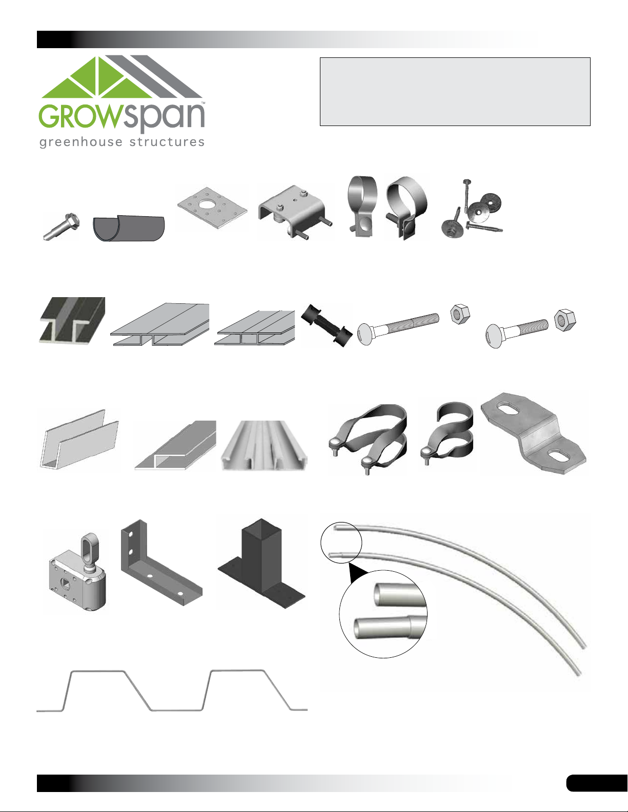
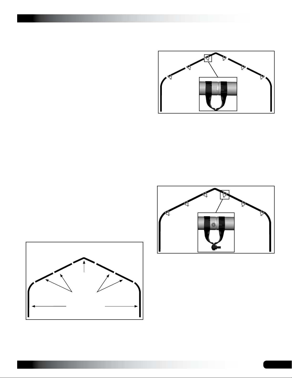
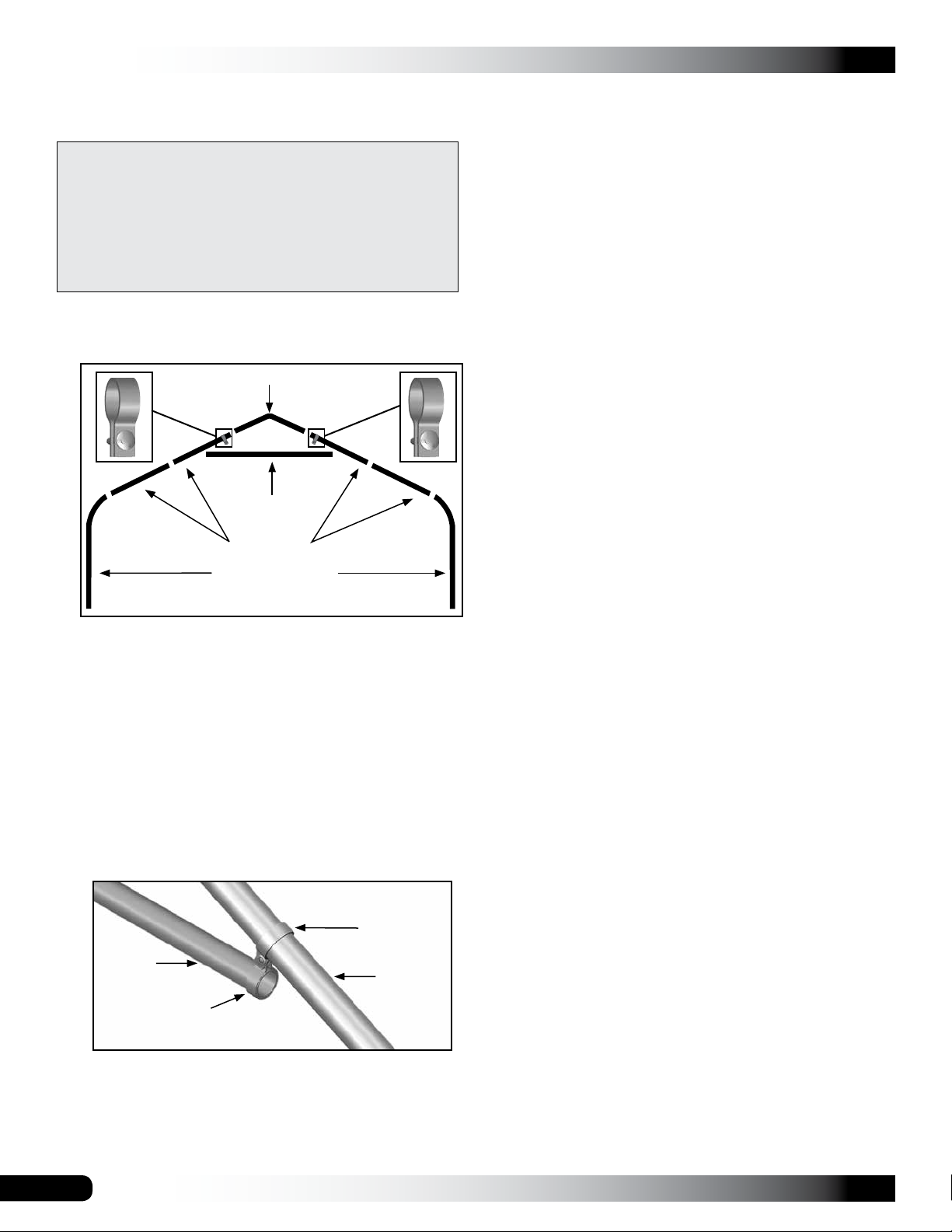
SQUARE TUBING INSTALLATION
Use the 102897 square tubing for all end wall framing. Use
the 104779 square tubing (plain ends) to secure overlap
seam between roof panels.
READ THIS DOCUMENT BEFORE YOU BEGIN.
Thank you for purchasing this GrowSpan™ greenhouse.
When properly assembled and maintained, this product will
provide years of reliable service. These instructions include
helpful hints and important information needed to safely
assemble and properly maintain the greenhouse. Please
read these instructions before you begin.
If you have any questions during the assembly, contact
Customer Service at 1-800-245-9881 for assistance.
SAFETY PRECAUTIONS
• Wear eye protection.
• Wear head protection.
• Wear gloves when handling metal tubes.
• Use a portable GFCI (Ground Fault Circuit Interrupter)
when working with power tools and cords.
• Do not climb on the greenhouse or framing during or
after construction.
• Do not occupy the greenhouse during high winds,
tornadoes, or hurricanes.
• Provide adequate ventilation if the structure is
enclosed.
• Do not store hazardous materials in the greenhouse.
• Provide proper ingress and egress to prevent
entrapment.
ANCHORING INSTRUCTIONS
Prior to assembling this greenhouse, please read the
MUST READ document included with the shipment.
WARNING: The anchor assembly is an integral part
of the greenhouse construction. Improper anchoring
may cause greenhouse instability and failure of the
structure. Failing to anchor the greenhouse properly
will void the manufacturer’s warranty and may cause
serious injury and damage.
LOCATION
Choosing the proper location is an important step before
you begin to assemble the structure.
The following suggestions and precautions will help you
determine whether your selected location is the best
location.
• Never erect the structure under power lines.
• Identify whether underground cables and pipes are
present before preparing the site or anchoring the
structure.
• Location should be away from structures that could
cause snow to drift on or around the building.
• Do not position the greenhouse where large loads
such as snow and ice, large tree branches, or other
overhead obstacles could fall.
• Always check local building codes before you begin.
SITE
After choosing a location, proper preparation of the site is
essential. The following site characteristics will help
ensure the integrity of the structure.
• A level site is required. The site must be level to
properly and safely erect and anchor the structure.
• If the site is not level, use footings to provide a secure
base to assemble the structure. Pre-cast concrete
blocks, pressure-treated wood posts, or poured
footings are all acceptable when properly used. (Some
shelters use ground posts or rafter feet.)
• Drainage: Water draining off the structure and from
areas surrounding the site should drain away from the
site to prevent damage to the site, the structure, and
contents of the structure.
WARNING: The individuals assembling this structure
are responsible for designing and furnishing all
temporary bracing, shoring and support needed during
the assembly process. For safety reasons, those who
are not familiar with recognized construction methods
and techniques must seek the help of a qualified
contractor.
ASSEMBLY NOTE: Install Tek screws using a clutched
drill driver running approximately 750 RPM while applying
approximately 50 lbs of force.
Do not use an impact driver to install Tek screws!

3
GROWSPAN™GOTHIC PRO GREENHOUSES AND SYSTEMS
Revision date: 05.29.19
ASSEMBLY PROCEDURE
Following the instructions as presented will help ensure
proper assembly of your greenhouse. Failing to follow
these steps may result in an improperly assembled and
anchored greenhouse and will void all warranty and
protection owner is entitled.
Steps outlining the assembly process are as follows:
1. Verify all parts are included in shipment. Notify
Customer Service for questions or concerns.
2. Read these instructions, the Must Read document, and
all additional documentation included with shipment
before you begin assembling.
3. Gather the tools, bracing, ladders (and lifts), and
assistants needed to assemble greenhouse.
4. Check weather before you install roof and
polycarbonate panels. Do not install panels on windy or
stormy days.
5. Re-evaluate location and site based on information and
precautions presented in documentation.
6. Prepare site (if applicable).
7. Assemble frame components in the order they are
presented.
8. Assemble frame including struts (if equipped).
9. Consult MUST READ document and properly anchor
assembled frame.
10. Install end wall framing.
11. Install, tighten, and secure end panels and doors.
12. Install main roof panels.
13. Read the care and maintenance information in next
column.
POLYCARBONATE PANELS
Do not allow panels to remain in direct sunlight with
protective film in place. Doing so will cause protective
film to become difficult if not impossible to remove before
installation.
Store panels indoors or cover with a light-colored
tarp until you are ready to install.
PANEL AND RIDGE CAP INSTALLATION NOTE
Depending on available equipment, it may be necessary to
construct a support structure to allow a person to reach top
of greenhouse from outside.
If a support structure has to be used, design structure to
support both the weight of structure and the person using it.
Use of a lift is strongly recommended.
CAUTION: Under no circumstances should support
structure allow any force or weight to be applied directly
to polycarbonate sheets! All supports must span
from rafter-to-rafter.
Consult a contractor if needed for additional information.
Take the necessary steps to protect polycarbonate panels.
POLYCARBONATE PANELS ARE NOT DESIGNED TO
SUPPORT WEIGHT.
NOTE: Position supports so they span from rafter-to-rafter
to protect panels. DO NOT use materials that will damage
or scratch panels. Cover panels to protect panel surface.
CAUTION: DO NOT place support structure directly
on polycarbonate panels; serious injury may occur.
Polycarbonate panels are not designed to support
excess weight.

GROWSPAN™GOTHIC PRO GREENHOUSES AND SYSTEMS
4Revision date: 05.29.19
REQUIRED TOOLS
The following list identifies main tools needed to
assemble shelter. Additional tools and supports may also
be required.
• Tape measure or measuring device; marker to mark
locations on the pipes
• Variable speed drill and power driver (cordless with
extra batteries works best)
• Metal-cutting saw; drill and drill bits
• Wrenches and socket set, or adjustable wrenches
• Scissors, utility knife, or tin snips; flat bar or putty knife
• Chalk line & caulk gun to apply sealant
• Hammers and gloves; adjustable and self-locking pliers
• Ladders, work platforms, and other machinery for lifting
designed to work safely at height of building
• Rope/cable for cover installation
UNPACK AND IDENTIFY PARTS
The following steps will ensure you have the necessary
parts before you begin.
1. Unpack the contents of the shipment and place where
you can easily inventory the parts. Refer to the Bill of
Materials/Spec Sheets.
2. Verify that all parts listed on the Bill of Materials/Spec
Sheets are present. If anything is missing or you have
questions, consult the Pictorial Parts Guide and all
diagrams for clarification, or contact Customer Service.
NOTE: At this time, you do not need to open the plastic
bags containing smaller parts such as fasteners or
washers (if equipped).
BASEBOARDS FOR FRAME — RECOMMENDED
These instructions describe installing a baseboard
(recommended) at ground level along each side of the
frame. Baseboard runs from front to back of frame.
This baseboard is not included and is customer supplied.
When installed properly the baseboard helps prevent
ground posts from sinking when anchored. Depending
on building, it also provides a surface to attach struts or
other building components. Secure baseboard using the
supplied FAH009B (1/4" x 4") bolts and FALB01B (1/4")
nuts.
Consult these instructions, or contact Customer Service for
additional information regarding baseboards.
Dotted line represents the anti-billow rope.
Example: Circles identify the ends of Rope #1.
ANTI-BILLOW ROPE INSTALLATION
TO PREVENT DAMAGE AND POSSIBLE INJURY,
INSTALL THE ANTI-BILLOW ROPES IN SHORT
LENGTHS ALONG EACH SIDE OF THE FRAME.
DO NOT INSTALL AS A SINGLE LENGTH TIED AT
EACH END OF THE BUILDING. DOING SO WILL
RESULT IN A LOOSE SIDE PANEL IF THE SINGLE
ROPE BREAKS DURING STRONG WINDS.
Rope
#1
Rope
#2
Rope
#3

5
GROWSPAN™GOTHIC PRO GREENHOUSES AND SYSTEMS
Revision date: 05.29.19
The following graphics and photos will help you identify the
different parts and show you how they are used. (Not all
parts are shown.)
Swaged
Unswaged
Swaged and Unswaged Rafter Sections
(not all pieces are shown)
FAH320B & FALB32B
Carriage Bolt & Hex Nut
102198
U-Channel Spring
CC6212
Fabric Clip
FA4482B
Tek Screw
104074
Square-to-Round Tube
Connect Bracket
FAH009B & FALB01B
Carriage Bolt & Hex Nut
104624
Square Tube Fitting
QH1330
Angle Bracket
104213
Aluminum
U-Channel Profile
104548
End Cap Profile
Doors/Fans/Vents
102570
Aluminum
Channel
Aluminum 8'
H-Channel Profile
102717
Gearbox
Drive
102569
Bearing
102921 & FA4484B
Neo-bonded Galvanized
Washers and Long Tek Screws
111928 and
111929
H-Channel -
Clear
104211
Double
U-Channel
QH1402 & QH1404
Band Clamps
102547
Cross Connector
102857
End Clamp
103496
Gear Box
103544
Mounting Plate
ASSEMBLY NOTE: Install Tek screws using a clutched
drill driver running approximately 750 RPM while applying
approximately 50 lbs of force.
Do not use an impact driver to install Tek screws!

GROWSPAN™GOTHIC PRO GREENHOUSES AND SYSTEMS
6Revision date: 05.29.19
H-CHANNEL INSTALLATION INSTRUCTIONS
The new H-channel design requires installation of the at side facing out with channel side toward
the building. Some diagrams and photos in this document show installation of original H-channel with
channel side facing out. Design of new H-channel does not allow channel-side out installation.
Use the diagrams on this page to install H-channel with at side facing out.
ATTENTION: Use only 1-1/2" Tek screws to attach H-channel to building frame. Do not use
shorter screws. They will not hold. Do not use washers on Tek screws when installing
H-channel.
ATTENTION: Install all twin-wall polycarbonate panels with UV-protected side toward the sun.
UV-protected side
toward sun.
Install 1-1/2" Tek screws through
H-channel into building frame.
H-Channel
Center Groove
Flat side toward the sun.
Flat
Side
Channel

7
GROWSPAN™GOTHIC PRO GREENHOUSES AND SYSTEMS
Revision date: 05.29.19
End Rafter
Interior
Rafter
Baseboard is
supplied by
customer.
Ground
Level
ATTENTION: Position purlins evenly during the
frame assembly. Use the rafter pipe joints as
guides when installing the end clamps, cross
connectors, and purlins.
Purlins
Ground
Post
Chord
GrowSpan™
Gothic Pro Greenhouses
and Systems
OVERVIEW
See illustration below to identify main parts of greenhouse.
1. Locate required parts for each assembly procedure.
2. Assemble rafters and frame. Anchor frame.
3. Assemble and install end walls.
4. Prepare and attach end panels.
5. Prepare and attach roof panels.
6. Attach roll-up side panels and anti-billow ropes.
7. Install doors.

GROWSPAN™GOTHIC PRO GREENHOUSES AND SYSTEMS
8Revision date: 05.29.19
LAY OUT THE BUILDING SITE
After the site is prepared, lay out the building site.
Taking these steps before assembling the shelter saves
time and ensures that the structure is positioned as
desired.
Ground posts must be driven to the proper depth. Width of
the shelter is measured from the center of one ground post
to the center of the remaining ground post.
SQUARE THE SITE
Gather the Parts:
• Ground Posts
• 5/16" x 2-1/2" Machine Bolts
• 5/16" Nuts
1. Identify a corner where a ground post will be positioned
and drive the first ground post into the ground.
NOTE: Insert the ground post driver into the top of
the ground post to protect the post and drive the post
into the ground. The top of the post will be one (1) foot
above the finished grade when properly driven.
3. Use a transit or line level to drive the second corner
post to the same depth as the first ground post.
4. Sting a line at least as long as the building from the first
stake at 90°.
NOTE: A transit can be used to ensure an accurate 90°
angle, or the 3-4-5 rule can be used. Refer to diagram.
Using multiples of 3-4-5 such as 6-8-10 or 12-16-20
helps to maintain an accurate 90° angle.
5. After squaring the position of the building, measure
the length (center-to-center) and drive the next corner
ground post.
6. Repeat the same step for the last corner post.
NOTE: The distance measured diagonally between
corner posts must be equal for the building to be
square.
7. Check all dimensions (and adjust if needed) before
driving the remaining posts to the required height.
8. After all corner posts are accurately installed, tie a
string line between the tops of the corner ground posts
on the same side of the shelter. The string is used to
identify the tops of all remaining ground posts. The
string must remain tight and level.
9. Use a tape measure to mark the 48" on-center
locations of the remaining ground posts.
10. Drive the remaining ground posts into the ground at the
required 48" on-center width and the height identified
by the string.
NOTE: Verify that the holes in the ground posts are in
the proper position and that each post is plumb and
driven to the correct depth.
11. Continue with the Rafter Assembly steps that follow.
ATTENTION: Position the pre-drilled holes facing to the
inside/outside of the shelter so they can be aligned with
the bolt holes in the rafter legs.
To align the bolt holes in the ground posts with those
in the rafter after driving the ground posts, insert a
tapered rod or pry bar into a ground post bolt hole and
turn the post using the rod or pry bar.
2. After the first corner ground post is in place, string a
line the width of the building (center-to-center) and
drive the second ground post into the ground just
enough to hold it in place.
Outside of
Shelter
Inside of
Shelter
Ground
Post

9
GROWSPAN™GOTHIC PRO GREENHOUSES AND SYSTEMS
Revision date: 05.29.19
ASSEMBLING THE GOTHIC PRO GREENHOUSE
FRAME COMPONENTS
After the site is prepared and an inventory of parts is
complete, continue with the rafter assembly.
NOTE: All rafter assemblies consist of rafter tubes and
purlin clamps. Consult the rafter diagram in the Quick
Start section of these instructions before and during the
rafter assembly process.
Assistance is required to assemble the greenhouse frame.
RAFTER ASSEMBLY
Gather the Parts:
• Rafter pipe (#34G190SS403)
• Rafter pipe (#34G190SS401D)
• Rafter pipe (#190S081)
• Chord pipe (#166P120)
• Band clamps (#QH1402 & #QH1404)
• End clamps (#102857)
• Tek screws (# FA4482B)
• Nut setter 3/8'' x 2-9/16 magnetic
END RAFTER ASSEMBLY
The end rafters include purlin end clamps and band
clamps. Install the purlin end clamps before the different
pipes of the rafters are connected. The band clamps for the
side struts are installed when the two (2) end rafters are set
onto the ground posts.
1. Select the seven (7) pipes needed to assemble the first
end rafter and arrange on a level surface.
2. Slide six (6) end purlin clamps (three on each side of
the peak) over the rafter pipes. Position all end clamps
at the rafter pipe joints. Position the end clamps as
shown.
NOTE: Position all purlin clamps at the rafter pipe
joints. Consult the Quick Start section for additional
information.
3. After slipping the clamps over the rafter pipes, insert
the swaged end of the rafter pipes into the plain ends
of the pipes to assemble the rafter.
4. Once the rafter is assembled, reposition the purlin
clamps over the pipe joints and install a Tek screw
through the rafter pipes to secure each joint.
IMPORTANT: To prevent damage to the cover and end
panels (if equipped), position the Tek screws so the
heads do not contact the cover when it is installed.
5. Repeat steps for to assemble the remaining end rafter
and set both end rafters aside.
End clamp as seen from inside the assembled frame.
(#34G190SS401D)
(#34G190SS403)
(#190S081)

GROWSPAN™GOTHIC PRO GREENHOUSES AND SYSTEMS
10 Revision date: 05.29.19
FRAME ASSEMBLY
After all ground posts are driven in place and rafters are
assembled, assemble the frame.
NOTE: The baseboards (strongly recommended) shown in
the diagrams throughout these instructions are not included
and must be supplied by the customer. Contact Customer
service at 1-800-245-9881 to purchase baseboards, or for
additional information.
ASSEMBLE AND PRE-MARK THE PURLINS
The following steps describe one way to speed the
assembly process and eliminate the need to measure each
purlin as it is installed. Pre-marking the purlins ensures that
an accurate spacing of the rafter assemblies is achieved
and maintained during assembly.
Gather the Parts:
• Pipe 1.315'' x 75'' swaged (#131S075)
• Pipe 1.315'' x XX'' plain (#131P0XX)
• Marker and tape measure
NOTE: The purlins are part of the assembled frame and
run perpendicular to the rafter assemblies. Each purlin
consists of 1.315" x 75" (#131S075) swaged pipes (number
is determined by shelter length) and one (1) 1.315" x XX"
(#131P0XX) plain pipe.
ATTENTION: The XX" represents the remaining length
required to reach the end of the shelter. Consult the Spec
Sheet for part identification.
1. Select the required pipe sections for one purlin and
connect these by inserting the swaged ends of the
pipes into the plain ends until the entire purlin is
assembled.
NOTE: Assemble the purlins in a location that is
accessible during the assembly of the frame, but will
not interfere with the process of lifting and setting the
rafters.
2. Verify that each pipe joint is properly seated.
NOTE: These pipes must be separated during the
assembly procedure. Do not fasten them together at
this time.
3. For the 48" rafter spacing, measure forty-eight and
three-quarters inches (48-3/4") from one end of the
assembled purlin and mark the distance on the pipe.
NOTE: This first measurement is three-quarters (3/4)
of an inch longer than the on-center rafter spacing
to account for the length of purlin pipe that extends
through the end purlin clamp of the first end rafter.
RAFTER ASSEMBLY (continued)
(#34G190SS401D)
(#166P120)
(#34G190SS403)
(#190S081)
INTERIOR RAFTER ASSEMBLY
Complete the following steps for the interior rafters.
1. Select the pipes for the first interior rafter assembly.
IMPORTANT: Install cross connectors during the frame
assembly. End clamps are not used for interior rafters.
2. Slide one (1) band clamp (#QH1404) onto each of the
upper straight pipes on both sides of the peak pipe.
3. Connect rafter pipes and secure each joint with a Tek
screw.
4. Center the chord at the peak of the assembled rafter,
add a band clamp (#QH1402) to each end, and attach
these band clamps to the band clamps on the rafter.
Secure the band clamps to the pipes using a Tek screw
when the chord is in position.
ATTENTION: ATTACH CHORD TO INTERIOR
RAFTER ONLY. Do not install chords on end rafters.
5. Once rafters are assembled, assemble the frame.
Band Clamp
(#QH1404)
Band Clamp
(#QH1402)
166P120
Interior Rafter
IMPORTANT: If rafter support kits were purchased
for all or some of the interior rafters, do not install
the 116P120 chord pipe at the peak (see below)
during the assembly of the interior rafters. These
are not used when support kits are installed.
Review the support kit instructions to install those
components during rafter assembly.

11
GROWSPAN™GOTHIC PRO GREENHOUSES AND SYSTEMS
Revision date: 05.29.19
FRAME ASSEMBLY (continued)
1. From the location marked in the previous step,
measure forty-eight inches (48") and make another
mark on the assembled purlin.
2. Continue to mark the purlin in 48" intervals until all
locations are marked. These marks help to maintain
the 48" on-center rafter spacing of the shelter during
assembly.
3. Repeat this procedure until all assembled purlins are
marked.
4. After assembling all rafters and pre-marking the purlins,
assemble the frame.
ASSEMBLE THE FRAME
After all ground posts are driven in place, rafters are
assembled and purlins pre-marked, assemble the frame.
Gather the Parts:
• All rafter assemblies and pre-marked purlins
• Band clamps (#QH1404)
• Cross connector (#102548)
• 5/16" x 2-1/2" Machine bolts and 5/16" nuts
• Lifts, ladders, and assistants
• Rope or cable
1. Carefully stand the first end rafter, slide a band clamp
onto each rafter leg, and place the leg pipes on the first
set of ground posts.
Brace the rafter in place to keep it straight. Depending
on the frame size, a lift and additional assistants may
be needed. Consult Quick Start section for details.
Rafter shown differs in design.
2. Secure the leg pipes to the ground posts using the
5/16" x 2 1/2" machine bolts and nuts.
Rafter shown differs in design.
ATTENTION: Stand the rafter so the nuts and bolts of
the end clamps are to the inside of the frame.
3. Use rope or cable to keep the rafter in position.
4. Carefully position the first interior rafter in place and
secure the leg pipes to the ground posts.
Rafter shown differs in design.
1st Interior Rafter
End Rafter
Inside of
Shelter
Outside of
Shelter
Rafter
Ground
Post
Band
Clamp

GROWSPAN™GOTHIC PRO GREENHOUSES AND SYSTEMS
12 Revision date: 05.29.19
FRAME ASSEMBLY (continued)
5. As the second rafter is steadied, remove one section of
pipe from one assembled purlin.
NOTE: Work from the end of the purlin where the
first measurement was taken during the pre-marking
procedure.
6. Insert the purlin pipe through an upper end clamp of
the end rafter and through a cross connector placed in
the same position on the interior rafter. Consult Quick
Start section for purlin location per frame.
7. Align the plain end of the purlin with the center of the
end rafter and rotate the purlin pipe so that the first
mark is visible (near the clamp of the interior rafter).
8. Tighten the end clamp and secure it to the rafter with a
Tek screw.
9. Install Tek screw through end clamp and into the purlin
pipe.
Purlin
End Rafter
10. Move to the interior rafter and align the mark on the
purlin with the center of the rafter to maintain the proper
spacing.
Interior Rafter Align mark with
center of rafter.
Purlin
11. Verify that the rafter spacing is forty-eight inches (48")
on-center (adjust as needed) and tighten the cross
connector.
12. Secure the cross connector to the rafter using a Tek
screw. See Quick Start section if needed.
13. Repeat Steps 6-12 to install the first section of each
purlin assembly for the first two rafters.
14. Choose another interior rafter assembly and set it
in position. DO NOT USE THE REMAINING END
RAFTER.
15. Secure the rafter legs to the ground posts as previously
described and steady the rafter.
16. Remove another section of purlin pipe from each pre-
marked purlin assembly and attach these to the rafter.
17. Verify that the distance between the rafters is 48"
center-to-center. Adjust the rafter forward or backward
as needed to maintain this dimension.
Interior Rafter
End Rafter
Do not allow the
purlin to extend
beyond the end
rafter.
End rafter view Interior rafter view
34' wide
(center-to-center)

13
GROWSPAN™GOTHIC PRO GREENHOUSES AND SYSTEMS
Revision date: 05.29.19
18. Secure the purlin pipe joint with a Tek screw.
19. Repeat the above steps as needed to stand and secure
the remaining interior rafters and purlins to complete
the frame assembly.
20. Slide a band clamp onto each leg of the remaining
end rafter, secure the rafter to the ground posts, and
attach the purlins to it. Verify that the end clamps are
positioned with the nut and bolt to the inside of the
assembled frame. Refer to the Quick Start section and
previous diagrams if needed.
NOTE: If the last end rafter is plumb and the purlin
extends beyond the end of the rafter, cut the last
section of purlin pipe to the required length.
FRAME ASSEMBLY (continued)
Dashed line shows
ground level.
Frame length may differ from actual frame.
21. Once all rafters are set and all purlins are in place and
secure, return to each pipe splice of each purlin and
verify that a Tek screw is installed. Install a Tek screw if
needed.
22. Remove any temporary bracing (if needed) and install
the baseboards and the side struts.
BASEBOARD INSTALLATION — RECOMMENDED
After installing all panels, installing a baseboard is
recommended. Minimum size is 2" x 6". Length
determined by building length. Materials for
baseboards are supplied by the customer.
Fasteners to secure baseboards to frame are included
with building.
A baseboard (2" x 6" minimum) helps keep ground posts
properly seated after anchors are installed.
BASEBOARD INSTALLATION (RECOMMENDED )
Gather parts:
• 2" x 6" (minimum) treated or recycled plastic lumber
(supplied by customer).
• 1/4" x 4" Carriage bolts and 1/4" Nuts (included)
The following procedure describes one way to install the
baseboards. Size and type of baseboard may require
additional installation steps.
Ground
Level
Inside of
Shelter
Outside of
Shelter
ATTENTION: Never attach two boards to the same ground
post. All baseboard splices should be between rafters as
shown above.
Use a short section of baseboard to secure separate
baseboards at a splice. Customer supplies all materials
to secure all baseboard splices.
General installation steps:
1. Position baseboard as shown and clamp or hold in
place against ground posts.
2. From inside the greenhouse, drill 5/16" holes through
ground posts, panels, and baseboard. (Ground posts
may come pre-drilled.)
3. Secure with 1/4" x 4" carriage bolts and nuts. Insert
from outside.
Depending on baseboard dimensions, countersink bolt
holes in baseboard as needed to allow bolts to reach
through all components.
4. Continue by installing side struts. See next page.

GROWSPAN™GOTHIC PRO GREENHOUSES AND SYSTEMS
14 Revision date: 05.29.19
SIDE STRUT INSTALLATION
There are four (4) side struts for the shelter. These struts
are positioned between the end rafters and the first interior
rafter on each side of the shelter.
Complete these steps to install the four (4) side struts:
Gather the Parts
• Struts
• Band clamps (#QH1404)
• Lag screw or nut and bolt (supplied by customer)
1. Locate one strut and position it between one end rafter
leg and the leg of the first interior rafter as shown
below.
Strut
End Rafter
Interior
Rafter
Baseboard is required
for this procedure.
Customer supplies the
baseboard.
Ground Level
2. Attach one end of the strut to the band clamp as shown
in the diagram below.
Strut
End Rafter
Band Clamp
3. Attach the remaining end of the strut to the baseboard
using a lag screw or nut and bolt (not included). See
the diagram that follows for location.
NOTE: A baseboard provides a place to attach each
strut and helps keep the ground posts at the required
depth. The customer is responsible for providing a
baseboard for this frame. If no baseboard is present,
attach the strut to the ground post using a Tek screw or
other customer supplied fasteners.
4. Repeat the above steps to attach the remaining side
struts to the shelter.
5. After securing the struts, verify that all clamps are
secured with a Tek screw to the rafters.
6. Verify that each pipe splice (purlin and rafter) is
secured with a Tek screw.
7. Complete the next procedure to anchor the assembled
frame.
ANCHOR THE ASSEMBLED FRAME
At this point, anchor the greenhouse frame. Consult the
MUST READ document for anchoring information and
suggestions. Please call customer service at 1-800-245-
9881 for additional anchoring information.
CAUTION: The anchor assembly is an integral part of
the greenhouse construction. Improper anchoring may
cause instability and failure of the structure to perform
as designed. Failing to anchor the shelter properly
will void the manufacturer’s warranty and may cause
serious injury and damage.
Photo shows the strut attached
to the inside of the customer-
supplied baseboard.
Attach strut
as shown.
End
Rafter
Ground Level
Baseboard
NOTE: Head of bolt on the band clamp must face the
toward the outside of the shelter.

15
GROWSPAN™GOTHIC PRO GREENHOUSES AND SYSTEMS
Revision date: 05.29.19
END WALL INSTALLATION
The steps to install the end walls for the greenhouse
include the following:
1. Install end wall framing. (See the diagrams in the Quick
Start section at the back of these instructions. Read the
installing accessories note below.)
2. Prepare polycarbonate end panels and attach.
3. Assemble doors and attach.
INSTALL END WALL FRAMING (Front and Back)
Site variations and different methods for anchoring the
greenhouse may require slight changes to be made to
these instructions. It is the responsibility of the owner/
builder to adapt these instructions as needed to adjust for
these and other differences.
A NOTE ABOUT INSTALLING THE END WALL
FRAMING FOR OPTIONAL HEATERS, VENT FANS, AND
MOTORIZED SHUTTERS (if equipped):
Optional accessories such as heaters, vent fans and
motorized shutter units are typically installed in the end
walls of this greenhouse. Additional horizontal framing
(included) is installed between the vertical end wall frame
tubes to mount these accessories. The spacing shown for
the end wall supports on the end frame diagrams may be
too narrow for the installation of some larger accessories.
Diagrams do not show framing for the accessories.
When framing the end wall, consult the installation
instructions for the accessories (if equipped), or measure
the width of the accessory to accurately space and position
the end frame tubes.
Consult the panel installation diagrams in the Quick Start
section to identify the verticals that can be moved.
MOVE ONLY THE VERTICAL SUPPORTS LABELED
AS NON-CRITICAL.
Before installing any greenhouse accessory, adhere to the
following:
• Consult the end frame diagrams before installing the
accessory horizontal framing.
• Move only those verticals labeled as "NON-CRITICAL"
on the end frame diagrams when deciding where to
install the additional horizontal framing for accessories.
• Consult the diagrams in the Quick Start section
showing the polycarbonate panel locations and the
locations of the aluminum trim and profile before
repositioning any end wall vertical.
• DO NOT REPOSITION THE END WALL VERTICALS
USED AT THE SEAM OF TWO (2) POLYCARBONATE
PANELS.
• Always consult the installation guides that shipped
with the accessory for additional precautions,
recommendations, and safety requirements.
• Before installing any electrical accessory, consult a
professional electrician for precautions and additional
assistance.
• For gas heaters, a professional, qualified service
technician must install the unit.
Complete these steps to install the accessory framing:
1. Based on the installation requirements and precautions
of the accessory, choose a location in the end wall to
mount the accessory, and cut a 1.5" x 1.5" frame tube
to the required length for framing.
2. Attach these horizontal frame tubes between the
vertical frame tubes of the end wall (at the required
height determined by the installation instructions
included with that accessory) using angle brackets.
INSTALL THE END WALL FRAME
Refer to the end frame diagrams (Quick Start section).
The materials and parts needed to assemble the end wall
frame include:
• Square tube (#102897): Full and cut-to-length.
• Angle brackets (#QH1330) & Band clamp (#QH1404)
• Square tube fitting (#104624)
• Square-to-round tube connect bracket (#104074)
• Carriage bolt (#FAH320) and Nut (#FALB32B)
• Tek screws (#FA4482B)
1. Locate the square metal tubing for the base tube of the
end wall. The base tube consists of 99" swaged tubes
and one (1) short section cut from a 102897square
tube. See Quick Start section for clarification.
2. Insert the swaged ends of the tubing into the plain ends
to connect the pieces, measure, and cut to length.
3. Position this assembled base tube on the ground
between the legs of the end rafter at the front of the
greenhouse and anchor it in place. This base tube will
be directly below and in line with the end rafter.

GROWSPAN™GOTHIC PRO GREENHOUSES AND SYSTEMS
16 Revision date: 05.29.19
4. Secure the base tube between the legs of the end
rafter using an angle bracket and Tek screws.
INSTALL THE END WALL FRAME (continued)
The bracket
shown in this
diagram can
be installed
with either its
short section
(as shown) or
the long section
attached to the
ground post.
Base Tube
Ground
Post
5. On the base tube surface facing the inside of the
greenhouse, install a short Tek screw at each joint and
then locate and mark the center of the base tube.
6. Consult the End frame diagram (Quick Start section)
and mark the rough opening for the width of the double
door assembly.
7. Place the band clamps on the end rafter above the
door as shown below. DO NOT TIGHTEN THE BOLTS
AT THIS TIME.
ATTENTION: The frame shown below may differ from
the end wall frame. Consult the diagrams in the Quick
Start section to view the frame for this shelter.
8. Select the tubing for the two vertical frame supports for
the sides of the double door. Each support includes:
9. Measure the distance between the top of the base tube
and band clamp (Step 7) to determine the length of the
first vertical section of the door frame tube.
10. Choose one (1) square tube (#102897), insert the
swaged end of the long tube into the plain end of
another tube and tap with a hammer to properly seat
the tubes at the joint.
11. On this assembled frame member, mark the length
determined in Step 9 (above) and subtract the amount
needed to account for the square-to-round tube
connect bracket, which is attached to the top of the
frame tube. See the diagram that follows.
12. Select a square-to-round tube connect bracket and
attach the bracket to one end of the vertical frame
member. Use a 5/16" drill bit to drill a hole through the
tube and attach the bracket to the tube using a nut and
carriage bolt.
13. Repeat Steps 9-12 for the remaining vertical frame
member for the door.
14. With the square-to-round tube connect bracket
attached to the top of each vertical door frame tube,
use the bolt in the band clamp to attach the bracket to
the band clamp. DO NOT TIGHTEN AT THIS TIME.
NOTE: The heads of the bolts for each clamp are to the
outside (or front/back) of the greenhouse. At this point,
the two vertical door frame members should be loosely
attached to the end rafter assembly.
• One (1) long 99" section of square tubing (#102897
swaged end)
• One (1) short section of square tubing. This is cut
from a swaged end tube (#102897).
• One (1) square-to-round tube bracket (#104074)
End Rafter
Square-to-
Round Tube
Connect
Bracket
Front (or outside)
of the greenhouse
Vertical Door
Frame Tube

17
GROWSPAN™GOTHIC PRO GREENHOUSES AND SYSTEMS
Revision date: 05.29.19
15. Using the marks on the base tube for the rough
opening for the door, attach the bottom of each vertical
frame member to the base tube using an angle bracket.
Consult the end frame diagram.
INSTALL THE END WALL FRAME (continued)
16. With the vertical door frame tubes attached at the
bottom and loose at the top, measure each frame
member to locate the height of the rough door opening
and mark the location on the inside of the door frame.
Consult the End Frame Diagrams Quick Start section
located at the back of these instructions.
Frame shown may differ from actual frame.
17. Using a level (or other means), verify that one vertical
door frame tube is plumb and tighten the band clamp
bolt to lock the first door frame member in place.
18. Choose the square tube for the door frame header and
cut the swaged end to the proper length for the width of
the rough door opening.
19. Using two angle brackets, attach the header tube to
the end wall assembly between the vertical door frame
tubes as shown.
Inside dimensions are shown. Diagrams may show a
different frame used for illustration purposes only.
20. Verify that both door frame verticals are plumb and
recheck the width of the rough door opening at the top
and bottom. Adjust if needed.
21. Cut the metal tube for the short, end wall supports
(positioned between the header and the end rafter) and
attach as shown in the following diagram.
92-1/4" 92-1/4"
Mark Here
Height of rough
door opening
Header
Height of rough
door opening
92-1/4"
96-3/4"
Width
Door Opening
Angle Bracket
Mark
Base Tube
Center of
Door Frame
Tube

GROWSPAN™GOTHIC PRO GREENHOUSES AND SYSTEMS
18 Revision date: 05.29.19
22. Use the end frame diagram to determine the number of
remaining vertical end frame supports and place one
band clamp on the end rafter for each of the remaining
vertical supports. Use the diagram for the location of
these clamps.
23. Using the end frame diagrams (Quick Start section),
measure and mark (on the base tube) the locations of
the remaining vertical end wall supports.
24. Choose the parts for each remaining vertical support
for the end wall framing. Each vertical support consists
of the following parts:
INSTALL THE END WALL FRAME (continued)
25. Use the steps presented earlier in these instructions
and the end frame diagrams to measure and cut each
section of square tubing for the remaining vertical
frame members.
ATTENTION: Remember to subtract the amount
needed to account for the square-to-round tube
connect bracket that will be attached to the top of each
remaining frame member.
26. Choose a square-to-round tube connect bracket and
attach the bracket to one end of the vertical frame
member. Use a 5/16" drill bit to drill a hole through the
tube and attach the bracket to the tube using a nut and
carriage bolt.
• Square tube: Longer verticals may require an
additional shorter length cut from a longer tube.
• One (1) square tube fitting (#104624) to attach the
support to the base tube of the end wall assembly.
• One (1) square-to-round tube connect bracket
(#104074) to attach the tubing to the band clamp
on the end rafter.
Front (or outside)
of the greenhouse
Square-to-
Round Tube
Connect
Bracket
Band Clamp
Position all screws, bolts
and clamps so they will
not damage the end wall
panels when panels
are attached to the
end wall frame.
End Rafter
27. With the square-to-round tube connect bracket
attached to the top of the frame member, place a
square tube fitting on the bottom of the frame member.
28. Align the center of the assembled frame member with
the center mark on the base tube and attach the top of
the frame member to the band clamp on the rafter. Do
not tighten.
29. Verify that the vertical end wall frame member is plumb
and use the short Tek screws to secure the square tube
fitting to the base tube.
Center Mark
30. Tighten the top band clamp and install a short Tek
screw through the clamp and into the rafter.
31. Repeat the procedure as needed to assemble and
install the remaining vertical end wall supports.
32. Return to the bottom of each frame member and install
a short Tek screw through the backside of each tube
fitting to secure the end frame support to the tube
fitting.
33. Once each end wall is assembled, return to each band
clamp and pipe splice of each base tube and verify that
a Tek screw is installed. Install a Tek screw if needed.
Inside view
of end rafter

19
GROWSPAN™GOTHIC PRO GREENHOUSES AND SYSTEMS
Revision date: 05.29.19
INSTALL END WALL FRAMING (BACK)
The greenhouse end walls (front and back) are identical
except as noted below and on the end frame diagrams.
If the back wall includes the optional double door kit
(additional purchase required), repeat the End Wall
Installation procedure and install the framing for the
remaining end wall.
If the back wall does not include an optional double door
kit, consult the end frame diagram to install the vertical
frame members.
Vertical dashed lines show where additional frame tubes
are installed when the optional double door is not used.
Consult the end frame diagram for additional information.
1. Read the note regarding the installation of optional
accessories at the beginning of the end wall installation
section.
2. Cut the 102897 tubes to the required length and attach
to the end wall framing.
3. Attach the frame supports at the top and bottom as
previous described.
Ground Level
Secure all polycarbonat panels as shown in the diagrams
and photos below.
GLAZING PANEL
8MM POLYCARBONATE
PANEL SPLICE "H" CHANNEL
TEK SCREW
END WALL FRAME TUBE
END WALL FRAME TUBE
TEK SCREW & NEO-BONDED WASHER
Use a Tek screw and washer to secure panel to end wall
frame. Do not crush panel when installing screws.
Diagram shows basic panel installation and fasteners used
to secure polycarbonte panels.

GROWSPAN™GOTHIC PRO GREENHOUSES AND SYSTEMS
20 Revision date: 05.29.19
END PANEL INSTALLATION
After the end wall framing is attached to the greenhouse,
attach the polycarbonate panels to the end wall framing.
The steps that follow describe one way to complete the end
wall panel installation.
The materials and parts needed to assemble the End
Panels include:
• Polycarbonate panels and white vent tape
• Aluminum U-Channel profile (#104213)
• Aluminum 8' H-Channel profile
• Tek screws (#FA4484B)
• Neo-bonded galvanized washers (#102921B)
Read the following information before starting:
• U-Channel profile is used to finish the roll-up side
edges of the polycarbonate panels.
• H-Channel profile is used to join two (2) separate
polycarbonate panels at the seam.
• Tek Screws and galvanized washers are used to
secure aluminum channel and panels to end wall
frame.
• Install the polycarbonate panels with the UV-protected
side to the outside. Mark this side with a marker if
needed after removing the protective film.
ATTENTION: The protective film must be removed
from the polycarbonate panels. Allowing the film to
remain intact and in direct sunlight will make the film
difficult if not impossible to remove.
• During preparation, rest the edges of the panels on
cardboard or other material to protect them from dirt
and damage.
• Seal the bottom edge of the panels with white vent
tape.
• Consult the polycarbonate panels (Quick Start section)
for the location and lengths of each panel. The
diagrams are located at the back of these instructions.
ATTENTION: Panels must be position as shown on the
panel diagrams. Using a panel in the incorrect place can
affect the placement of subsequent panels. In addition, the
amount of aluminum profile used between panels and to
finish the panel edges may not be adequate if additional
seams are created. Begin at the door end of the building.
NOTE: Install all accessories (fans, vents, heaters, etc.)
after installing all polycarbonate sheets.
Complete the following general steps to install the end wall
panels.
1. Consult the panel location diagrams, select one
polycarbonate panel, begin at the edge of the opening
for the double door, and work to the outside edge of the
end wall.
See the X in the diagram below for the first panel.
NOTE: Remove the protective film. When needed, an
upper panel is cut to length after attaching it to the end
wall frame and rafter.
Always remove the protective film and mark and install
the UV-protected side to the outside of the greenhouse.
Mark UV Side X
2. Apply white vent tape to the bottom of the lower panel
and then install the aluminum U-channel profile to the
edge of the panel adjacent to the door as shown on the
Polycarbonate Panels diagram.
EXCESS
TRIMMED AND
USED HERE
EXCESS
TRIMMED AND
USED HERE
Dashed line and small arrows (above) show where to
install the white vent tape. Do not install tape in any
other location on any other end panels.
X
This manual suits for next models
3
Table of contents
Other GrowSpan Lawn And Garden Equipment manuals

GrowSpan
GrowSpan 105163F User manual

GrowSpan
GrowSpan 113577 User manual

GrowSpan
GrowSpan 115021 User manual

GrowSpan
GrowSpan Gothic Pro Series User manual

GrowSpan
GrowSpan 106202 User manual

GrowSpan
GrowSpan 108207 User manual

GrowSpan
GrowSpan Gothic Premium H Series User manual

GrowSpan
GrowSpan 105169F User manual

GrowSpan
GrowSpan Estate Elite 104609 User manual

GrowSpan
GrowSpan 105158F User manual