2
• Male threads between the 2 suction tube
(19) parts
• Male threads on the suction tube (19) end
that fits into the pump inlet.
2. Now hand tighten the elbow (10) to the pump
outlet. Once the elbow (10) can no longer be
hand tighten, take the adjustable spanner &
tighten the elbow (10) by about half a turn.
Open end of the elbow (10) should be facing
away and not in the direction of the motor (1).
3. Take the bung adaptor (14) & hand tighten it
onto the 2" drum opening. Bung adaptor (14)
has a large 2" thread & a small 1-1/2" thread. 2"
thread goes into the drum, whereas the 1-1/2"
thread is for connecting the bung adaptor (14)
to the pump.
4. Connect the two halves of the suction tube
(19). Now connect the suction tube (19) to the
pump inlet and hand tighten it.
5. Lift the pump from the handle and insert the
suction tube (19) into the drum through the 2"
opening on the drum. Use the convenient spin
collar (13) mounted at the pump inlet to fasten
the pump onto the Bung adaptor (14).
6. Ensure that there is about 2" (50 mm) gap
between the bottom of the tank / drum & inlet
of the suction tube (19) allowing easy entry of
media into the suction tube (19).
7. Take about 30 ml of oil being dispensed &
pour it into the pump outlet through the elbow
(10). This will ensure that the gear (7) stays
lubricated & makes it easier for the pump to
prime.
8. Take the hose (20) & connect one threaded
end to the elbow (10) at the pump outlet. Hose
(20) has a hex nut at the threaded end which
can be tightened to the elbow (10) using
adjustable spanner.
9. Connect the other end of the hose (20) to the
ball valve (21).
10. Connect the discharge spout (22) to the ball
valve (21).
11. Turn the toggle switch (24) to ‘OFF’ (up)
position and connect the power cable (23) to
the AC power socket.
12. The pump is now ready for use.
In-line pump installation
This pump can additionally be mounted on a wall
for in-line operation. This is particularly done in a
shop environment where the pump may be used
with waste oil.
Note: For waste oil application, pump already has
a strainer installed at the bottom of the suction
tube (19).
Pump can be installed using a mounting bracket
(not provided, but can be ordered separately).
This bracket is a simple right angle bracket with
two mounting holes that uses the motor (1)
mounting holes on one side of the motor (1) to
attach it to the bracket. The bolts (6) used to
SAFETY INFORMATION
• Keep the work area clean and dry. Damp or
wet work areas can result in injury.
• Store idle equipment. When not in use, tools
and equipment should be stored in a dry
location to inhibit rust
• Use the right tool for the job. Do not attempt
to force small equipment to do the work of
larger industrial equipment.
• Do not modify this equipment and do not use
this equipment for a purpose for which it was
not intended.
• Check for damaged parts. Before using this
product, carefully check that it will operate
properly and perform its intended function.
Replace damaged or worn parts immediately.
WARNING!
• Read and understand all instructions. Failure to
follow all instructions listed above may result in
electric shock, fire and/or serious injury.
PACKAGE CONTENT
DESCRIPTION QUANTITY
Pump & motor assembly fitted with power cable 1
Suction tube (2 parts) 1
Bung adaptor 1
Elbow 1
Hose 1
Ball valve 1
Discharge spout 1
PTFE tape 1
O.I.P.M. 1
TOOLS NEEDED
• Adjustable spanner
BEFORE INSTALLATION
• Eyes protection: Wear a protective mask or
protective eyewear.
• Skin protection: Avoid repeated and
prolonged contact of fluids with the skin by
wearing impermeable protective gloves.
• Check that the product has not suered any
damage during transport or storage. Clean the
inlet and outlet openings, removing any dust
or residual packing material.
• Keep the pump away from heat and sharp
edges. Check the pump for wear and make
certain that all connections are secure.
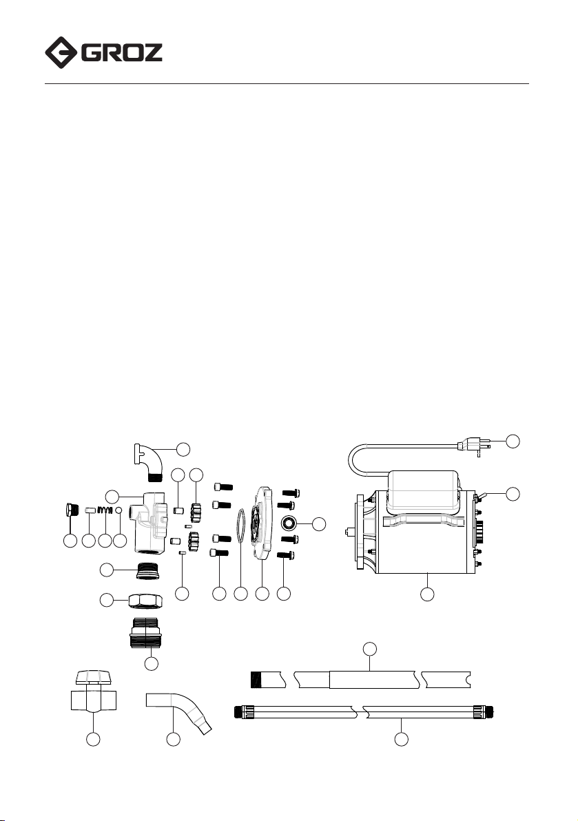
INSTALLATION
(Refer “EXPLODED VIEW”)
1. Wrap around PTFE tape on the following male
threaded joints. This will ensure a leak-proof
connection
• Male threads on the elbow (10)
• Male threads on the fitting ends of the hose
(20)
OPM.indd 2 12-09-19 4:02:14 PM