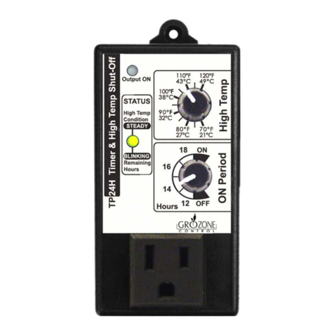
Grozone Control TP24H User manual

www.grozonecontrol.com
USER GUIDE
TP24H
24-Hour mer
with High Temp Shut-Off

SAFETY NOTICE
3
PRODUCT DETAILS 4
INSTALLATION & OPERATION
8
SETTINGS
9-10-11
OPTIONAL SETTINGS 12-13
QUICK TROUBLESHOOTING GUIDE
14-15
COMPLETE TROUBLESHOOTING GUIDE
16-17
WARRANTY & CUSTOMER SERVICE
18-19
GENERAL DESCRIPTION 5-6-7
TABLE OF CONTENTS

3
SAFETY NOTICE
IMPORTANT SAFETY INSTRUCTIONS
SAVE THESE INSTRUCTIONS
DANGER
TO REDUCE THE RISK OF FIRE OR ELECTRIC SHOCK,
CAREFULLY FOLLOW THESE INSTRUCTIONS.
To reduce the risk of electric shock, disconnect power to the 120V
electrical outlet before installing or removing the unit. When removing the
electrical wall plate, it may fall across plug pins or become displaced.
To reduce the risk of electric shock, this product has a grounding type plug
that has a third (grounding) pin. This plug will only fit into a grounding
type power outlet. If the plug does not fit into the outlet, contact a
qualified electrician to install the proper outlet. Do not change the plug in
any way.
3

4
PRODUCT DETAILS
Operaon and Specificaons
Temperature setpoint between 70°F and 120°F (21°C to 49°C).
6- temperature probe works from +32°F to +212°F (0°C to 100°C).
On mes range from 12, 14, 16 and 18 hours.
On/Off Status at power up is adjustable.
Internal 24-hour Clock precision : Less than 30 minutes per year.
Internal 24-hour Clock will maintain On/Off cycles for a minimum of 48
hours during a power outage.
Electrical Specificaon: See the rang label on your product.
4

5
GENERAL DESCRIPTION
The TP24H is a 24-hour mer with high temp shut-off designed to control
lighng systems, two 600 Was ballast or one 1000W ballast at 120V with
ON cycles from 12 to 18 hours.
Delay
A 20-minute Output ON delay is acve when:
· 120V power is applied to the TP24H OR when power returns aer a pow-
er outage. See "Note 1"
· A high temperature condion is met. If the room cools down in less than
20 minutes, the output will remain OFF unl the 20-minute delay has
completely elapsed.
When the output remains "standby" during count down, the Output ON led
is flashing. To stop the delay immediately, turn lower knob to ON (wait for
the output to turn ON), then reset it to a value between 12 and 18 hours.
No Delay
If the unit has been unplugged and the baery has fully discharged (note 1),
the TP24H will restart without delay at power up. In this case, the ON/OFF
cycles has been lost and must be reset as described in the "Installaon &
Operaon" Secon.
Note 1: The internal rechargeable baery retenon me lies between 48 and 96
hours. The baery is fully recharged 30 minutes aer the power has been ap-
plied to the TP24H.
5
6
Status LED
ON: The Status Led turns on when a High Temperature condion is met.
OFF: The Status Led turns off when the lower knob is in ON or OFF posi-
on.
BLINKING: The Status Led is blinking to indicate the remaining me
(number of hours le in the current cycle).
The Status Led will be BLINKING during the ON or the OFF cycle to indicate
the remaining me (in hours) unl the beginning of next cycle (transion
from ON to OFF or from OFF to ON). The indicator is blinking in mulple of
5 pulses.
Examples:
· To indicate 7 hours remaining
The Status Led will blink in this sequence: 5 pulses, one short pause, 2
pulses and one long pause, repeatedly.
· To indicate 3 hours remaining
The Status Led will blink in this sequence: 3 pulses and one long pause,
repeatedly.
GENERAL DESCRIPTION
Note: If the Status Led indicates a remaining me of 3 hours, it means the actual
remaining me is between 2 and 3 hours. During the last hour, the STATUS blinks
only once between each long pause.
6

7
Output ON LED
ON: The Output ON Led is ON when there is power applied to the 120V
front panel output.
OFF: The Output ON Led is OFF when there is no power applied to the
120V front panel output (during OFF cycles or when a high temperature
condion is present).
Flashing: The Output ON Led will flash when it should be ON but it is
maintained OFF during the 20-minutes ON delay.
GENERAL DESCRIPTION
7

8
INSTALLATION & OPERATION
Values Seng
Plug into 120 VAC outlet (see security noce on page 1).
Place the sensor at desired locaon.
Connect your equipment in the front panel outlet (MAX 15A).
High Temp
Installaon is now complete
Output On
ON Period
8

9
A. Unplug unit.
SETTINGS
B. Set lower knob to ON.
C. Plug in the unit and wait 2 seconds.
Cycles Seng
To start a new ON cycle
D. Set lower knob from
18 to 12 hours.
9

10
A. Unplug unit.
SETTINGS
B. Set lower knob to OFF.
C. Plug in the unit and wait 2 seconds.
Cycles Seng
To start a new OFF cycle
D. Set lower knob from
12 to 18 hours.
10

11
SETTINGS
High Temperature Sengs
The output will turn OFF as soon as the ambient temperature reaches
this seng. The output will turn back ON when the ambient tempera-
ture has cooled down by 5°F (or 10°F, see "Oponal Seng") or when
the output remained OFF for a minimum of 20 minutes.
· Set the upper knob to desired
High temperature limit.
11

12
A. Unplug the unit.
Set both knobs fully clockwise.
B. Within 5 seconds, plug in the
unit then set both knobs fully
counter clockwise.
C. "Output ON" light indicator
turns ON.
TP24H is now in 5°F cool down
OPTIONAL SETTINGS/5°F COOL DOWN
Change to 5°F cool down
The TP24H has been set to perform in 5°F Setback (cool down).
12

13
A. Unplug the unit.
Set both knobs fully counter
clockwise.
B. Within 5 seconds, plug in the unit
then set both knobs fully
clockwise.
C. "Output ON" light indicator
turns OFF.
TP24H is now in 10°F cool down
OPTIONAL SETTINGS/10°F COOL DOWN
Change to 10°F cool down
13

14
Wait 2 seconds
and then turn
the lower knob
to 12H
Quick Troubleshoong Chart
Product Model: TP24H
BEFORE YOU START
· Unplug UNIT
· Plug load into UNIT*
· Set lower knob to ON (fully clockwise)
· Set upper knob to 120°F (fully clockwise)
Yes Status indicator
is blinking 12
mes (5-5-2)
A
B
C D
Plug-in the unit
Product
Defecve
Output ON indicator
& load are OFF
No
Turn lower knob to 18H
Output ON
indicator & load
are ON
QUICK TROUBLESHOOTING GUIDE
= Steps
14

15
Turn upper
knob fully
clockwise
(120°F)
Status indicator
is blinking 18
mes (5-5-5-3)
Turn lower
knob fully
counter clock-
wise
(OFF)
Turn lower
knob to 12H
Warm up temp probe
in your hand
QUICK TROUBLESHOOTING GUIDE
*Before test, check if load is
working properly.
Output ON &
status indicators
turn OFF
Nothing
happens
Output ON indica-
tor turns OFF &
status indicator
turns ON
Output ON & status
indicators are steady
ON or OFF
Output ON &
status indicators
are flashing
Product
Defecve
Product
Good
E F G H
I
J
Turn upper
knob fully
counter clock-
wise
(70°F)
No
Yes
Output ON & status
indicators stay ON
Output ON
indicator & load
turn OF
Output ON indicator
& load stay OFF
Product
Defecve Product
Defecve
15

16
COMPLETE TROUBLESHOOTING GUIDE
24-Hour Timer with High Temp Shut-off
TP24H
1 – Before you start
2 – Test
***IMPORTANT: READ AND FOLLOW THESE INSTRUCTIONS BEFORE
STARTING THE TEST.
· DO NOT CONNECT UNIT BEFORE STEP 1 OF THE TEST.
· CONNECT A LOAD INTO THE UNIT.
· TURN LOWER KNOB FULLY CLOCKWISE (ON).
· TURN UPPER KNOB FULLY CLOCKWISE (120°F)
STEPS HANDLING AND TEST DESCRIPTIONS EXPECTED RESULTS
1
Output ON Led and Front Outlet
check
· Plug the unit into any 120V outlet
or power bar.
The Output ON light
indicator and the load
will turn ON.
2
Status Led check
· Turn the lower knob to 12H.
· Turn the lower knob to 18H
The Status light indicator
will blink 12 mes (5-5-
2).
The Status light indicator
will blink 18 mes (5-5-5-
3).
16

17
COMPLETE TROUBLESHOOTING GUIDE
STEPS HANDLING AND TEST DESCRIPTIONS EXPECTED RESULTS
3
Lower knob check
· Turn lower knob fully counter
clockwise (OFF).
· Turn lower knob to 12H.
The Output ON light
indicator and the Status
light indicator will turn
OFF.
The Output ON light
indicator and the load will
turn ON.
4
Upper knob and Temperature probe
check
· Warm up the temperature probe
in your hand and turn the upper
knob fully counter clockwise (70°
F).
· Turn the upper knob fully
clockwise (120°F).
The Output ON light
indicator will turn OFF
and the Status light
indicator will turn ON.
The Output ON light
indicator and the Status
light indicator will flash
(20-minute delay).
17

18
WARRANTY & CUSTOMER SERVICE
DO YOU HAVE A PROBLEM WITH YOUR CONTROLLER ? PLEASE READ
THESE INSTRUCTIONS CAREFULLY AND SAVE THEM FOR FUTURE
REFERENCE.
1. I think my controller is damaged, or it simply does not work as
indicated in the user guide, what should I do?
· Please refer to the troubleshoong steps. Follow these instrucons
carefully, step by step. The controller should work as described in the
“Expected results” column of the Complete Troubleshoong Guide.
Do you need assistance on execung the Troubleshoong steps?
1. Contact us at 1-855-262-1800
2. Send us an EMAIL at ser[email protected]
3. VISIT our Technical Support Center at
www.grozonecontrol.com/techsupport.html
Technical Support is available Monday through Friday, from 8:00 AM to
8:00 PM, Eastern Time.
18

19
2. I’ve been through the troubleshoong steps. What do I do if I meet a
problem at any of these steps? Is my product covered by the
WARRANTY?
· Grozone controllers are covered by a 3-year warranty (*). We will
replace any DAMAGED PRODUCT WITH A BRAND NEW PRODUCT.
· Covered or not covered? We do not authorize the replacement of fully
working products nor altered (tampered) products. The Troubleshoong
steps will help you idenfy a damaged product. Do not hesitate to
contact us or contact your retailer to make sure the controller is not fully
working or damaged before returning it to the store.
· My product is not fully working or damaged, I want a replacement unit:
in order to get a replacement product, you MUST return all modules
and applicable accessories to the retailer. To avoid being charged for
the accessories, be sure to include all pieces. Thanks for your
cooperaon.
· Any Grozone Control product that is returned with obvious signs of user
neglect will not be covered by the warranty. Grozone Control exercises
the right to make final decisions in these maers.
(*)The warranty period begins from the date of purchase at the retail level.
The retailer/consumer must keep their proof of sale/purchase. Otherwise,
Grozone Control will consider the manufacturing date to apply the warranty
coverage.
IMPORTANT MESSAGE TO RETAILERS
Retailers must call Grozone Control to get authorisaon to replace the
defecve product and a RMA number.
1-855-262-1800
WARRANTY & CUSTOMER SERVICE
19

Other manuals for TP24H
1
Table of contents
Languages:
Other Grozone Control Timer manuals

Grozone Control
Grozone Control CY3 User manual

Grozone Control
Grozone Control CY1 User manual

Grozone Control
Grozone Control CY3 Operating instructions

Grozone Control
Grozone Control Cyclestat-3 CY3 User manual

Grozone Control
Grozone Control CY1 User manual

Grozone Control
Grozone Control TP24H User manual