Grundig GCA-C2357V User manual

GCA-C2357V.123.1.26.09.2013
Owner's Manual
EN
© ASP AG
Analogue Cameras
GCA-C2357V 1/4" CCD Vandal Resistant Dome Camera AFZ 3.8~38
mm ICR 28 IR LED 700L ext.


Content:
1. Important Safety Instructions 1
2. Package Contents 2
3. Installation 2
4. Installation 3
1. 3-Axis Gimbal Adjustment 4
5. Control Stick 3
1. OSD Control 3
2. Zoom & Focus Adjustment 3
6. OSD Menu 4
1. FOCUS
2. EXPOSURE
3. WHITE BAL (White Balance)
4. DAY&NIGHT
5. BACKLIGHT
6. DNR (Digital Noise Reduction)
7. IMAGE ADJ
8. SPECIAL 12
9. RESET 17
10. EXIT 17
1. Important Safety Instructions
Be sure to use only the standard adapter that is specified in the specification sheet.
Using any other adapter could cause fire, electrical shock, or damage to the product.
Incorrectly connecting the power supply may cause explosion, fire, electric shock, or
damage to the product. Do not connect multiple products to one single adapter.
Exceeding the capacity may cause abnormal heat generation or fire.
1
English

Do not place conductive objects (e.g. screwdrivers, coins or any metal items) or
containers filled with water on top of the product. Doing so may cause personal injury
due to fire, electric shock, or falling objects.
If any unusual smells or smoke comes out of the unit, stop using the product. In this
case, immediately disconnect the power source and contact the service center.
Continued use in such a condition may cause fire or electric shock.
If this product fails to operate normally, contact the nearest service center. Never
disassemble or modify this product in any way. (GRUNDIG is not liable for problems
caused by unauthorised modifications or attempted repair.)
To prevent fire or electric shock, do not expose the inside of this device to rain or
moisture.
2. Package Contents
These parts are included:
3. Installation
Do not install this product in a location subject to high temperature (over 55°C), low
temperature (below -25°C), or high humidity. Doing so may cause fire or electric shock.
Keep out of direct sunlight and heat radiation sources. This may cause fire.
Do not install the unit in humid, dusty or sooty locations. Doing so may cause fire or
electric shock. Install it in a place with good ventilation.
When installing the unit, fasten it securely and firmly. A falling unit may cause personal
injury.
2English

If you want to relocate the already installed product, be sure to turn the power off and
then move or reinstall it.
4. Part Names
3English

4.1. 3-Axis Gimbal Adjustment
5. Control Stick
5.1. OSD Control
- Pressing the SET UP stick: Accesses the menu mode or confirms the setting.
- UP / DOWN: Chooses the desired menu.
- LEFT / RIGHT: Sets up the value of the selected menu and changes the settings.
5.2. Zoom & Focus Adjustment
- UP / DOWN: Sets the zoom.
- LEFT / RIGHT: Sets the focus.
4English

6. OSD Menu
1. Press the SET UP stick to access the menu mode.
2. Select the desired feature by using UP/DOWN.
3. If there is a setting for this feature on the right side of the screen, use LEFT/RIGHT to
switch between the settings and confirm your choice by pressing the stick. If an ENTER
arrow (↵) is displayed, press the stick to access the according submenu.
4. In the sub-menus, please press with the stick on RETURN to return to the previous
menu.
5. To exit the menu, please press the stick on EXIT in the main menu.
FOCUS: Here you can configure the focus
and zoom setting.
EXPOSURE: This function is used to
control the light exposure.
WHITE BAL: You can control the white
balance under different lighting conditions
here.
DAY&NIGHT: This function is used to improve the camera's sensitivity at night or when
the brightness level of the ambient environment is low.
BACKLIGHT: You can control the highlight and backlight compensation here.
DNR: This noise reduction function is to decrease the noise which can be generated
under low light conditions.
IMAGE ADJ: You can set different picture related settings like mirroring, sharpness, hue
and gain.
SPECIAL: Configures camera related functions and data.
RESET: This function is for resetting the camera to factory default.
EXIT: Here you can exit the menu.
6.1. FOCUS
Here you can configure the focus and zoom setting.
5
English

FOCUS MODE [AUTO, INTERVAL,
MANUAL, ONE-PUSH]:
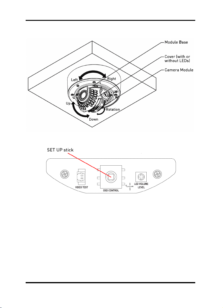
- AUTO: The focus will be permanently on.
Increase or decrease the optical zoom
(ZOOM) or the digital zoom (D-ZOOM)
using the UP and DOWN directions of the
SET UP stick. Through enabling D-ZOOM
(ON), the digital zoom will be activated once
the optical zoom comes to an end. The
focus will automatically be adjusted when
the lens zooms in or out.
- INTERVAL: The focus will be adjusted according to the time interval set in AF.
INTERVAL.
- ONE-PUSH: Focus will be just once automatically adjusted, after the zoom position
was changed. Increase or decrease the optical zoom (ZOOM) or the digital zoom (D-
ZOOM) using the UP and DOWN directions of the SET UP stick. Press the SET UP stick
once the desired image quality is obtained.
- MANUAL: Increase or decrease the optical zoom (ZOOM) or the digital zoom (D-
ZOOM) using the UP and DOWN directions of the SET UP stick. Press the SET UP stick
once the desired image quality is obtained. The focus can be manually adjusted,
independent of the moving zoom.
D-ZOOM [ON, OFF] :
Set the digital zoom to ON or OFF.
ZOOM START [1~8] :
Set the start position of the zoom lens from 1 to 8.
ZOOM STOP [8~120] :
Set the end position of the zoom lens from 8 to 120.
ZOOM SPEED [SLOW, NORMAL, HIGH, QUICK] :
Adjust the zoom speed, choose one of the 4 speed options (SLOW, NORMAL, HIGH,
QUICK).
MIN. DIST [10CM, 50CM, 1M, 2M, 3M, 5M, 10M, INF] :
Adjust the minimum object distance, the adjustable range is from 10cm to endless (INF).
AF INTERVAL [3 SEC ~ 255 SEC] :
Please see FOCUS MODE > INTERVAL.
ZOOM POS INIT [ON, OFF] :
The camera moves to the set ZOOM position when the power is turned on and an initial
ZOOM position has been set.
6.2. EXPOSURE
This function is used to control the light exposure.
6English

BRIGHTNESS [0~100] :
Sets the value of auto exposure operations.
As the value increases, the screen gets
brighter.
SHUTTER [x265, x128, x64, x32, x24, x16, x14, x12, x10, x8, x6, x4, x2, AUTO, OFF,
FLK, 1/250, 1/500, 1/1000,1/2000, 1/5000, 1/10000, 1/20000, 1/50000, 1/100000] :
Control the image brightness by adjusting the shutter speed.
AGC (Auto Gain Control) [HIGH, MANUAL, OFF, LOW, MEDIUM] :
This function is used to create brighter images.
- HIGH: Wide range gain value adjustment.
- MANUAL: Select the gain value range under MANUAL AGC (-3dB~28dB).
- OFF: Disabled.
- LOW: Narrow range gain value adjustment.
- MEDIUM: Medium range gain value adjustment.
IRIS [AUTO, MANUAL] :
- AUTO: The iris is automatically activated upon illumination.
- MANUAL: This option is used for manual iris configuration. Select a value from 0 to 255
under MANUAL IRIS.
MANUAL AGC:
Please see AGC > MANUAL.
MANUAL IRIS:
Please see IRIS > MANUAL.
SENS-UP LIMIT [OFF, x1~x256] :
This feature ensures clear images at night or under low light conditions.
6.3. WHITE BAL (White Balance)
This function is used to control the white balance under different lighting conditions.
Adjusting the setting calibrates the camera for correct and natural colour rendering.
7
English

MODE [ATW, AWB, AWC→SET,
INDOOR, OUTDOOR, MANUAL] :
- ATW: Select this mode when the colour
temperature is between 1,800˚K and
10,500˚K.
- AWB: This function is used to search for
colours that match the ambient environment
well. Select this mode when the colour
temperature is between 3,000˚K and
7,000˚K.
- INDOOR: Select this mode when the colour temperature is about 3,100˚K (indoor light).
- OUTDOOR: Select this mode when the colour temperature is about 5,100˚K (outdoor
light).
- AWC→SET: To find the optimal luminance level for the current environment, point the
camera towards a sheet of white paper and press the SET UP stick. If the environment
changes, re-adjust this setting.
- MANUAL: Select this option to fine-tune the White Balance manually. Set the White
Balance first by using the ATW or the AWC mode. After that switch to MANUAL mode,
fine-tune the White Balance and then press the SET UP stick.
NOTE:
The White Balance may not work properly under the following conditions. If that is the
case, select the AWC mode (automatic mode).
1. When the colour temperature of the environment surrounding the subject is out of the
control range (e.g. clear sky or sunset).
2. When the ambient illumination of the subject is dim.
3. When the camera is directed towards a fluorescent light or is installed in a place
where the illumination changes dramatically, the White Balance operation may become
unstable.
6.4. DAY&NIGHT
This function is used to improve the camera's sensitivity at night or when the brigthness
level of the ambient environment is low.
MODE [AUTO, COLOR, BW, EXTERNAL] :
- AUTO: This mode switches to ‘Colour’ in a
normal environment, but switches to ‘B/W’
mode when the ambient illumination is low.
To set up the switching time for AUTO
mode, press the SET UP stick. In B/W
mode, you can turn the BURST signal ON
or OFF.
8English

- COLOR: The picture will be always displayed in colour.
- BW: The picture will be always displayed in black & white. In BW mode, you can turn
the BURST signal ON or OFF.
- EXTERNAL: Day and Night can be distinguished by the external output.
DWELL TIME [0SEC~60SEC] :
You can select here the duration of the change from day to night mode and night to day
mode.
D→N LEVEL [0~255] :
Adjust the DAY→NIGHT switch level from 0~255 by moving the SET UP stick to the left
or right direction.
N→D LEVEL [0~255] :
Adjust the NIGHT→DAY switch level from 0~255 by moving the SET UP stick to the left
or right direction.
BURST:
In BW mode, you can turn the BURST signal ON or OFF.
SMART IR:
This option controls the IR LED (bright portion base), saturation is not expected.
When selecting ↵, the following submenu will appear.
- MODE [ON, OFF] :
Activate the SMART IR function by
selecting ON.
- GAIN [1~100] :
The gain can be adjusted from 1 to 100.
- H. START (0~14): Here you can set the starting position of the area from the side.
- V. START (0~14): Here you can set the starting position of the area from the top.
- WIDTH (0~15): Here you can set the horizontal size of the area.
- HEIGHT (0~15): Here you can set the vertical size of the area.
NOTE:
When the SMART IR setting is ON, the functions D-WDR, HSBLC, and BLC cannot be
used in B/W mode, but only in colour mode.
6.5. BACKLIGHT
This function is used for backlight and highlight compensation.
9
English

MODE [OFF, D-WDR, BLC, HSBLC] :
- OFF: Deactivated.
- D-WDR: This function provides intelligent
light level control to overcome even strong
backlight conditions.
- BLC: BLC is used to counterbalance the screen image by increasing the brightness so
that a subject which appears dark due to a strong backlight can be displayed in more
detail.
- HSBLC (Highlight Suppression Back Light Compensation): This function is used to
surpress or mask a strong light source (for example, headlights of cars during night-
time) so that other subjects can be seen in more detail.
LEVEL:
Depending on which option you have chosen under MODE, you can set different levels
here. For BLC Mode, you can choose a compensation level from LOW, MIDDLE or
HIGH. For HSBLC mode, you can set the sensitivity trigger level between 0 and 100. For
D-WDR mode, you can set the WDR level between 0 and 15.
AREA:
When choosing BLC under MODE, you can enter the AREA sub-menu by pressing the
SET UP stick. The following sub-menu will then appear.
Here you can set the area of the BLC.
> H. START (0~14): Here you can set the
starting position of the area from the left.
> V. START (0~14): Here you can set the
starting position of the area from the top.
> WIDTH (0~15): Here you can set the
horizontal size of the area.
> HEIGHT (0~15): Here you can set the
vertical size of the area.
When choosing HSBLC under MODE, you can enter the AREA sub-menu by pressing
the SET UP stick. The following sub-menu will then appear.
10 English

Here you can set the area of the HSBLC.
> HBLC (ON, OFF): You can turn the HBLC
ON or OFF.
> H. START (0~14): Here you can set the
starting position of the area from the left.
> V. START (0~14): Here you can set the
starting position of the area from the top.
> WIDTH (0~15): Here you can set the
horizontal size of the area.
> HEIGHT (0~15): Here you can set the
vertical size of the area.
DISP. MODE [NIGHT, ALL DAY] :
When HSBLC is chosen, you can set here when this function should be activated.
- ALL DAY: HSBLC will always be on.
- NIGHT: HSBLC will only be active in night mode.
6.6. DNR (Digital Noise Reduction)
This function is used to improve the picture quality by filtering the noise which is
generated under low bright light conditions. You can set different levels here.
3DNR MODE [OFF, ON, SMART] :
- OFF: Deactivated.
- ON: The compensation proportion will be
adjustable from 0 to 255 under 3DNR
LEVEL.
- SMART: The DNR level will be
automatically changed, depending on the
movement. The compensation proportion is
adjustable from 0 to 255 under 3DNR
LEVEL.
3DNR LEVEL [0~255] :
Please see SMART and ON under 3DNR MODE.
3DNR SENSE [0~100] :
When SMART is set under 3DNR MODE, you can set here a level between 0 and 100.
FDNR MODE [MANUAL, AUTO, OFF] :
Here you can set the FDNR (Fog Digital Noise Reduction) to OFF, MANUAL or AUTO.
The FDNR function improves the clarity of the image taken in poor conditions such as
fog, smoke, rain or snow.
FDNR LEVEL [0~31 or 0~10] :
If MANUAL is set under FDNR MODE, you can set here a level between 0 and 31. If
AUTO is set under FDNR MODE, you can set here a level between 0 and 10.
11
English

FDNR COLOR [0~10] :
If FDNR MODE is set to MANUAL, you can set here the colour level of FDNR from 0 to
10.
FDNR EDGE [0~10] :
If FDNR MODE is set to MANUAL, you can set here the edge enhancement of FDNR
from 0 to 10.
NOTE:
If the 3DNR function is used, the cancellation of the noise will be excellent. The higher
the compensation proportion is raised, the better the effect of noise cancellation will be,
but a ghost effect may also occurr.
6.7. IMAGE ADJ
This function is used to adjust the picture that is displayed on the screen.
FREEZE [OFF, ON] :
The FREEZE function allows to hold the
image of the camera.
REVERSE [OFF, H-REV, HV-REV, V-REV]:
Mirrors the video signal horizontally,
vertically, or both.
NEGATIVE [OFF, ON] :
This function is used to invert the colours in the picture.
SHARPNESS [0~31] :
This function is used to adjust the sharpness of the displayed image.
MONITOR:
Here you can adjust a few settings regarding the monitor you use.
When selecting ↵, the following submenu will appear.
12 English

- MODE [LCD, CRT] :
> LCD: Select this option when you use an
LCD monitor.
Then you can adjust the gamma, pedestal
level and blue/red gain setttings.
> CRT: Select this option when you use a
CRT monitor.
Then you can adjust the gamma, pedestal
level and blue/red gain setttings.
- GAMMA [0.05~1.00] :
Adjust the GAMMA level between 0.05 and 1.00.
- PED LEVEL [0~63] :
Adjust the PED level between 0 and 63.
- COLOR LEVEL [0~255] :
Adjust the saturation level between 0 and 255.
6.8. SPECIAL
This menu is for configuring various camera settings.
To enter the submenus of the functions, select ↵on the right.
6.8.1. CAM TITLE
This menu is used to assign a unique name
to a camera. You can enter up to 20
alphanumeric or special characters for the
CAM TITLE.
Using the four directions of the SET UP
stick, switch between the characters. Press
the SET UP stick to make a desired figure.
DISPLAY [OFF, ON] :
Select ON if you want to display the camera title in the picture/on the screen.
CLEAR [OFF, ON] :
Select ON if you need to delete the letters.
POSITION:
Select ↵and press the SET UP stick to be able to move the display position of the
CAMERA ID. To exit this setting, press the SET UP stick.
13
English

6.8.2. COMM ADJ
This function is for setting up the communication information.
CAM ID [000-255] :
Choose a desired ID for this camera.
PROTOCOL [VISCA, LG-NEW,
SAMSUNG, PELCO-D, ALL] :
Set up the protocol. When you choose ALL,
you can use all protocols.
BAUDRATE [2400, 4800, 9600, 19200,
38400] :
Choose a desired value for the baudrate.
UTC DELAY [0-255]:
Here you can set a time interval for the input of the UTC signal.
6.8.3. LANGUAGE
The language is set to ENG (English).
6.8.4. MOTION
This function is used to detect moving objects in the monitored area.
AREA MODE [OFF, ON] :
Select ON to be able to set and activate the
motion detection areas.
AREA SEL [AREA 1~4] :
Select a monitoring area out of the 4
monitoring areas and set the options below
for the selected monitoring area.
DETECT MODE [ON, OFF] :
Select ON to activate the selected monitoring area.
14 English

H. START [0~240] :
Here you can set the starting position of the area from the left.
V. START [0~128] :
Here you can set the starting position of the area from the top.
WIDTH [0~240] :
Here you can set the horizontal size of the area.
HEIGHT [0~128] :
Here you can set the vertical size of the area.
SENSITIVITY [0~100] :
Here you can set the sensitivity of the motion detection. When the value is high, even
small movements can be detected.
ALARM OUT [OFF, OSD&AREA, AREA, OSD] :
- OFF: Deactivated.
- OSD&AREA: When motion is detected, "MD" will blink in the top right corner of the
screen, and also the detection area will be displaying the motion on the screen by a
flickering yellow block.
- AREA: When motion is detected, the detection area will be displaying the motion on the
screen by a flickering yellow block.
- OSD: When motion is detected, "MD" will blink in the top right corner of the screen.
6.8.5. PRIVACY
This function is used to mask specific areas within the frame of the camera.
MODE [OFF, ON] :
Select ON to be able to set and to activate
the privacy areas.
MASK SEL [AREA1~8] :
Select a mask out of the 8 mask areas and
set the options below for the selected mask.
MASK DISPLAY [ON, OFF] :
Select ON to activate the setting for the selected mask area.
AREA SET:
Here you can adjust the size and form of the mask area.
When selecting ↵, the following submenu will appear.
15
English

- P/T LOCK [ON, OFF] : Choose OFF to be
able to change the vertical/horizontal
position of the mask area under TILT POSI
and ZOOM POSI.
- WIDTH [0~80] : Here you can set the
width of the mask area.
- HEIGHT [0~60] : Here you can set the
height of the mask area.
- PAN POSI [-200~200] : If P/T LOCK is set to OFF, you can set here the horizontal
position of the mask area.
- TILT POSI [-220~220] : If P/T LOCK is set to OFF, you can set here the vertical
position of the mask area.
- ZOOM POSI: Here you can zoom in the picture, the mask size will be changed
accordingly.
- MASK RESET [ON, OFF] : When choosing ON, the mask will be minimised to a
certain size and will be dragged to the middle of the screen.
COLOR [0~15] :
Choose one of the 16 colours for the mask areas.
TRANSPARENCY [0~3] :
Choose one of the 4 transparency levels for the mask areas.
MASK RESET [ON, OFF] :
When choosing ON, the mask will be minimised to a certain size and will be dragged to
the middle of the screen.
6.8.6. OSD DISPLAY
This function is for determining what information will be displayed on the screen.
CAM ID [ON, OFF] :
The RS-485 address will be displayed.
ZOOM MAG [ON, OFF] :
In case of lens operation, the zoom
magnification level will be displayed for 5
sec.
ZOOM BAR [ON, OFF] :
In case of lens operation, the zoom bar will
be displayed for 5 sec.
16 English

FUNC. OSD [ON, OFF] :
In case of lens operation, the zoom/focus operation status will be displayed as "ZF" for 5
sec.
INIT. LOGO [ON, OFF] :
When ON is selected, the firmware version will be displayed when the camera is turned
on.
6.8.7. LSC
This function is for compensating the quantity of light differences of the center of the
lens and the periphery.
MODE [ON, OFF] :
Turn the lens shading compensation ON or
OFF.
LSC GAIN [0~255] :
The lens shading compensation gain is
adjustable from 0 to 255.
H. CENTER [-128~127] :
Choose the horizontal center level for the lens shading compensation. If you change the
value of H. CENTER and V. CENTER, the center point will be moved.
V. CENTER [-128~127] :
Choose the vertical center level for the lens shading compensation. If you change the
value of H. CENTER and V. CENTER, the center point will be moved.
6.8.8. PRESET
This function is used for a quick and easy setup according to the installation environment.
POSITION [IR MODE, INDOOR,
OUTDOOR, LOW LIGHT, HALL WAY,
CUSTOM, SPEED DOME] :
Here you can choose one of the 7 possible
preset modes. Please refer to the table
below that shows the settings for the preset
modes.
17
English

Preset Settings :
RECALL:
First you need to load the settings for the preset mode that you selected under
POSITION. Move the SET UP stick in the right direction and wait until CALLED is
displayed. Then the settings for the selected preset mode are loaded.
SAVE [ON, OFF] :
When CUSTOM is selected under POSITION, you can make the settings for your own
customised mode and then you can save here your settings when you select ON.
CLEAR [ON, OFF] :
When CUSTOM is selected under POSITION, you can clear here the settings that were
made for the CUSTOM mode when you select ON.
6.9. RESET
All settings will be restored to factory default.
6.10. EXIT
Exits the menu setting.
18 English
Table of contents
Other Grundig Digital Camera manuals

Grundig
Grundig GSC 530 User manual

Grundig
Grundig GSC 110 User manual

Grundig
Grundig GD-CT-AC2805B User manual

Grundig
Grundig GSC 510 User manual

Grundig
Grundig GBW-G0116X User manual

Grundig
Grundig GSC 100 User manual

Grundig
Grundig PICCA DMC 5200 User manual

Grundig
Grundig PICCA DMC 5100 User manual

Grundig
Grundig GD-CI-AC2615M User manual

Grundig
Grundig Livance LC 1100 User manual