LED ROADWAY LIGHTING
INSTALLATION INSTRUCTION MANUAL AND
MAINTENANCE FOR LED ROADWAY LIGHTING
USER INSTRUCTION
* GRUPPE LIGHTING had taken the outmost care in design and manufacture of its products
in order to guarantee as far as possible, maximum safety and risk-free operation when
used correctly. Nevertheless, in compliance with accident prevention laws, users are
required to ensure that all personnel responsible for the installation, handling use and
sale of products are totally familiar with the information supplied by the company and
fully acquainted with any necessary precautionary, must be made available, as and
when required to any company or persons engaged in the installation of
GRUPPE LIGHTING products.
GENERAL
* This luminaire is designed for outdoor lighting service, and should not be used in areas
of limited ventilation , or in high ambient temperatures. Best result will be obtained if
installed and mantained according to the following recommendations.
UNPACKING
*
This luminaire has been properly packed so that no parts should have been damaged
during transit. Inspect to confirm.
CAUTION: Glass must be protected from surface chips and scratches.
Even minor surface damage will reduce the breakage resistance to
a fraction of its initial strength
.
WARNING
* Installation should be performed by a qualified electrician in compliance with these
instructions and applicable standards.
* Disconnect the mains power supply before installing or replacing the lamp.
* Make sure that the rated voltage of the lamp is compatible with the supply voltage.
* Make sure that the lamp is compatible with the ambient conditions in which it must
operate.
* Make sure that the mains supply circuit is equipped with protection devices.
* The safety of the fitting is guaranteed only by the proper use of the following instruction,
so we recomment to keep them.
* Before using the network's connection during lamps setting or replacement make sure to
take the tension off.
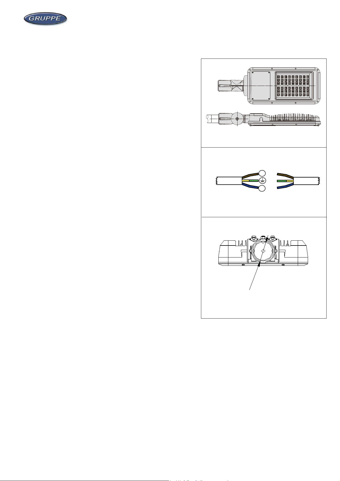
POLE MOUNTING ( FIGURES 1 & 2 & 3 )
* Put pole into the slipfitter area marked in the "A" .
* Level the luminaire and tighten internal clamp screws alternatively
up to a torque between 13,3 and 15,1 Nm. (Fig 3)
* Fix the supply cable through the cable entry E and connect wires to the plug in/out
connector terminal. (Fig 2)
FIG 2
FIG 3
FIG 1
Specifications are subject to change without prior notice
Page 1
Cable Connection
* Mounting Height = 6 ~ 12m
N
L
Ø 60
MODEL : Percorso


