GS STAUFF OCS User manual

Local Solutions For Individual Customers Worldwide
Manual
Oil Condition Sensor OCS
and Accessories
STAUFF OCS-Manual-EN.indd 1 18.06.2014 10:27:57

The companies of the STAUFF Group assumes any legal liability or responsibility for the accuracy, completeness, or usefulness of any information,
product or process disclosed in this document.
Reference herein to any specic commercial product, process, service by trade name, trademark, manufacturer, or otherwise, does not constitute or
imply its endorsement, recommendation, or favouring by STAUFF.
Subject to change without prior notication.
Content
1. Overview .......................................................................................................................................................................................................................6
2. Oil Quality Index.............................................................................................................................................................................................................7
2.1. Introduction............................................................................................................................................................................................................7
2.2. Oil Degradation ......................................................................................................................................................................................................7
2.3. OQI Value vs Loss Factor Percentage ......................................................................................................................................................................7
2.4. Traffic Lights ..........................................................................................................................................................................................................7
2.5. Numbering/Levels ..................................................................................................................................................................................................7
2.6. Clean Point (Start Point)..........................................................................................................................................................................................8
2.7. Loss Factor Percentage and OQI Value....................................................................................................................................................................8
2.8. Scaling ..................................................................................................................................................................................................................8
3. Oil Condition Sensor Type OCS - Technical Data .............................................................................................................................................................9
3.1. Safety Notes...........................................................................................................................................................................................................9
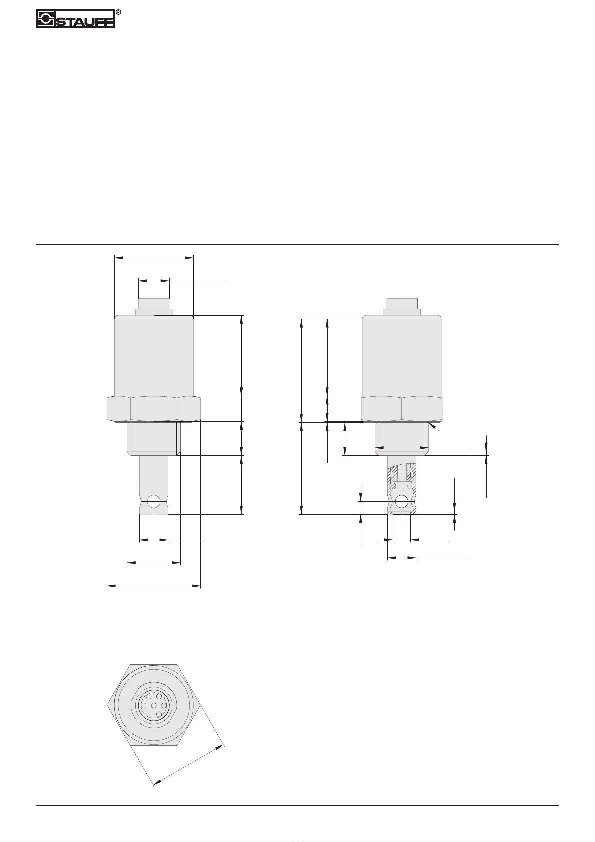
3.2. Dimensions ............................................................................................................................................................................................................9
3.3. Mechanical Installation..........................................................................................................................................................................................10
3.4. Precautions ...........................................................................................................................................................................................................10
3.5. Choosing the Sensor Mounting Location................................................................................................................................................................10
3.6. Fitting Method – Summary ....................................................................................................................................................................................10
3.7. Cleaning and Maintenance ....................................................................................................................................................................................10
4. Oil Condition Sensor Type OCS - Electrical Specifications ..............................................................................................................................................11
4.1. Electrical Installation .............................................................................................................................................................................................11
4.1.1. Power Supply.............................................................................................................................................................................................11
4.1.2. Wiring Diagram..........................................................................................................................................................................................11
4.2. 4 ... 20 mA Output.................................................................................................................................................................................................12
4.2.1. Sensor Output............................................................................................................................................................................................12
4.2.2. Oil Condition ..............................................................................................................................................................................................12
4.2.3. Oil Temperature .........................................................................................................................................................................................13
4.2.4. Sensor Calibration .....................................................................................................................................................................................13
4.3. RS485 Communications ........................................................................................................................................................................................13
2www.stauff.com
STAUFF OCS-Manual-EN.indd 2 18.06.2014 10:27:57

www.stauff.com 3
4.4. CANbus.................................................................................................................................................................................................................13
4.4.1. Introduction ...............................................................................................................................................................................................13
4.4.2. Wiring........................................................................................................................................................................................................13
4.4.3. Communications Objects ...........................................................................................................................................................................14
4.4.3.1. Bit Rate.......................................................................................................................................................................................14
4.4.3.2. SYNC Event.................................................................................................................................................................................14
4.4.3.3. Transmit PDO1 ............................................................................................................................................................................14
4.4.3.4. NMT Start-up and heartbeat........................................................................................................................................................14
4.4.3.5. Receive SDO...............................................................................................................................................................................14
4.4.3.6. Transmit SDO ..............................................................................................................................................................................14
4.4.4. Object Dictionary Communication Profile ...................................................................................................................................................14
4.4.4.1. Object Dictionary Device Profile – Analogue Input Function Block................................................................................................16
4.5. Modbus.................................................................................................................................................................................................................17
4.5.1. Hardware...................................................................................................................................................................................................17
4.5.2. Configurable Parameters............................................................................................................................................................................18
4.5.3. Communication Mode................................................................................................................................................................................18
4.5.4. Message Framing ......................................................................................................................................................................................18
4.5.4.1. Function Codes ...........................................................................................................................................................................18
4.5.4.2. Query..........................................................................................................................................................................................19
5. Oil Condition Display Type OCD .....................................................................................................................................................................................22
5.1. Overview...............................................................................................................................................................................................................22
5.2. Electrical Installation .............................................................................................................................................................................................22
5.3. Mechanical Installation..........................................................................................................................................................................................22
5.3.1. Dimensions................................................................................................................................................................................................23
5.4. Reading Values......................................................................................................................................................................................................24
5.4.1. Oil Condition ..............................................................................................................................................................................................24
5.4.2. Oil Temperature .........................................................................................................................................................................................24
5.5. Sensor Calibration .................................................................................................................................................................................................24
5.5.1. Resetting the Zero Point.............................................................................................................................................................................24
5.6. Data Logging.........................................................................................................................................................................................................25
5.7. Technical Details ...................................................................................................................................................................................................25
6. USB Interface Type OCS I-USB Interface ........................................................................................................................................................................26
STAUFF OCS-Manual-EN.indd 3 18.06.2014 10:27:57

7. OCS Software ...............................................................................................................................................................................................................27
7.1. Installation ............................................................................................................................................................................................................27
7.1.2. Removal ....................................................................................................................................................................................................28
7.2. Start-up ................................................................................................................................................................................................................29
7.3. Main Screen..........................................................................................................................................................................................................29
7.3.1. Device Explorer..........................................................................................................................................................................................30
7.3.1.1. Automatic Search........................................................................................................................................................................30
7.3.1.2. Refresh All ..................................................................................................................................................................................30
7.3.1.3. Collapse All .................................................................................................................................................................................30
7.3.1.4. Expand All...................................................................................................................................................................................30
7.3.1.5. Device Types...............................................................................................................................................................................30
7.3.2. Main Screen - Oil Condition Sensor Type OCS ............................................................................................................................................31
7.3.2.1. Current Display ...........................................................................................................................................................................31
7.3.2.1.1. Oil Condition / Oil Temperature ...................................................................................................................................31
7.3.2.1.2. Zero Sensor................................................................................................................................................................31
7.3.2.2. Stored Readings..........................................................................................................................................................................32
7.3.2.2.1. Clear Readings ...........................................................................................................................................................32
7.3.2.2.2. Export.........................................................................................................................................................................33
7.3.2.3. Quick Trend.................................................................................................................................................................................33
7.3.2.3.1. Save Image ................................................................................................................................................................34
7.3.2.4. Configuration ..............................................................................................................................................................................34
7.3.2.4.1. Sensor Details ............................................................................................................................................................35
7.3.2.4.2. Communication ..........................................................................................................................................................35
7.3.2.4.3. Current Oil..................................................................................................................................................................35
7.3.3. Main Screen - Oil Condition Display Type OCD ...........................................................................................................................................37
7.3.3.1. Current Display ...........................................................................................................................................................................37
7.3.3.1.1. Oil Condition / Oil Temperature ...................................................................................................................................37
7.3.3.1.2. Zero Sensor................................................................................................................................................................37
7.3.3.2. Configuration ..............................................................................................................................................................................37
4www.stauff.com
STAUFF OCS-Manual-EN.indd 4 18.06.2014 10:27:57

www.stauff.com 5
7.3.3.3. Download Data ...........................................................................................................................................................................38
7.3.3.3.1. Data Logging Details ..................................................................................................................................................38
7.3.3.3.2. Set Date and Time ......................................................................................................................................................38
7.3.3.3.3. Set Logging Interval....................................................................................................................................................38
7.3.3.3.4. Downlaod All ..............................................................................................................................................................39
7.3.3.3.5. Download Last ‘n’.......................................................................................................................................................39
7.3.3.3.6. Delete All....................................................................................................................................................................40
7.3.4. File ............................................................................................................................................................................................................41
7.3.4.1. Update Oil Database ...................................................................................................................................................................41
7.3.4.2. Exit .............................................................................................................................................................................................41
7.3.5. Print ..........................................................................................................................................................................................................42
7.3.6. Setup.........................................................................................................................................................................................................42
7.3.6.1. Options .......................................................................................................................................................................................42
7.3.6.1.1. Data Capture ..............................................................................................................................................................42
7.3.6.1.2. Time Interval...............................................................................................................................................................43
7.3.6.1.3. Auto Detect Sensors ...................................................................................................................................................43
7.3.7. Help...........................................................................................................................................................................................................43
7.3.7.1. About ..........................................................................................................................................................................................43
7.3.7.2. View Activity Log.........................................................................................................................................................................44
7.3.7.2.1. Clear Log....................................................................................................................................................................44
7.3.7.2.2. Export.........................................................................................................................................................................45
7.3.7.2.3. Refresh.......................................................................................................................................................................45
7.3.7.2.4. Close..........................................................................................................................................................................45
7.4. Technical Support..................................................................................................................................................................................................46
7.4.1. Installing Updates ......................................................................................................................................................................................46
7.4.2. Updating the Oil Database..........................................................................................................................................................................46
7.4.3. Company Logos.........................................................................................................................................................................................46
7.4.4. Log File and Readings File Location ...........................................................................................................................................................46
This software is designed to work with Windows XP, Windows Vista, Windows 7 and Windows 8 both 32 bit and 64 bit only.
STAUFF OCS-Manual-EN.indd 5 18.06.2014 10:27:57

1. Overview
The STAUFF Oil Condition Sensor OCS allows real time reporting of the condition of the oil in virtually any piece of equipment which uses oil.
The OCS sensor utilises sophisticated electronics to indicate the current condition of oil relative to the initial condition of new oil.
Based on the OCS sensor output, the oil drain down intervals may be extended on large industrial equipment where the cost of replacing and monitoring
the oil is expensive. The OCS sensor triggers an investigation into the quality of the oil, preventing the need for expensive routine maintenance.
The STAUFF Oil Condition Sensor OCS can reduce the overall operating cost of machinery through the removal of routine inspections, waste oil disposal
and subsequent renewal.
The OCS sensor sensor is designed to be easy to use in a variety of congurations depending on the monitoring equipment to which you would like to
interface. It uses a simple four wire connection to connect to its power supply and output the oil condition and temperature on individual 4 ... 20 mA
current sink outputs, with an additional two wires if you would like to use an RS485, CANBus or Modbus interface to connect to an external device.
6www.stauff.com
STAUFF OCS-Manual-EN.indd 6 18.06.2014 10:27:57

2. Oil Quality Index
2.1. Introduction
All industries have a various ways to describe oil wear and oil condition, for example some would talk about percentage of life used, other would
look at hours left or perhaps only consider the TAN/TBN crossover point but there are many more.
To make it far easier to monitor and trend the overall oil condition, regardless of your current method, we have introduced the “Oil Quality Index”.
2.2. Oil Degradation
The “Oil Quality Index” has been designed to be easy to understand, to give a very good level of accuracy and to create a common language for
describing overall oil wear and oil condition, which can also be combined with other methods such as ISO cleanliness levels and laboratory test results.
It is important to understand that oil degradation is exponential and the “Oil Quality Index” reects this.
2.3. OQI Value vs Loss Factor Percentage
The underlying value which the sensor is recording for the oil condition is the Loss Factor Percentage which is then converted into an OQI value, this is
explained later.
2.4. Trafc Lights
First and foremost the OQI scale offers a trafc light view of oil condition, so there is a green section, an amber section and a red section to illustrate „OK“,
„Warning“ and „Alarm“ respectively.
OK
Alarm
Warning
2.5. Numbering/Levels
To enable accurate monitoring and trending of the oil condition these three sections of the Oil Quality Index are then divided up, giving you 13 green levels,
4 amber levels and 3 red levels.
OK
Alarm
Warning
The QOI levels are then numbered from 1 to 20, starting at the rst green level.
www.stauff.com 7
STAUFF OCS-Manual-EN.indd 7 18.06.2014 10:27:58

2.6. Clean Point (Start Point)
We now have to consider the starting point for an oil, the Clean Point (Start Point) for most oils will generally be between 3 and 5 on the OQI scale.
The actual value will depend on a number of factors but most importantly how pure the base stock is and what additive packages have been included.
Clean Point
From this point as the oil begins to deteriorate the value will increase.
Please note that the reason why we do not start at 1 on the OQI scale for a brand new clean oil, as some oils can be improved by using sophisticated online
or ofine ltration, therefore an oil can also improve on the OQI scale, as well as deteriorate.
2.7. Loss Factor Percentage and OQI Value
The OCS sensor is looking Loss Factor Percentage to determine how degraded or worn as oil is.
When we start with a clean oil we will have a Loss Factor Percentage of approximately 0 % and then as the oil changes and degrades this Loss Factor
Percentage will increase.
For most applications an oil would be considered to be moving towards its “end of life” when we see a Loss Factor Percentage of 25 % and then the oil
would be considered at the “end of life” when we reach a Loss Factor Percentage of 30 % or above.
The Loss Factor Percentage value is then converted into an OQI value using the table below:
2.8. Scaling
Oil wear is not linear, it tends to follow more of an exponential curve, therefore any initial change in wear and/or contamination will tend to be fairly slow,
however as the wear and/or contamination increases the rate of at which the oil degrades will become faster and faster.
With this in mind the OQI scale is linear within the green level (1-13) but we reduce the amount of change required by half for the amber level (14-17) and
red level (18-20).
8www.stauff.com
STAUFF OCS-Manual-EN.indd 8 18.06.2014 10:27:59

3. Oil Condition Sensor Type OCS
– Technical Data
3.1. Safety Notes
Please pay attention to following safety notes:
►OCS sensor should not be used near combustible gases or liquid.
►Never reassemble, repair or tamper with the OCS sensor.
►Ensure that the supply voltage is within the specied range.
►Ensure the load currents do not exceed the rated value.
►Check all the wiring for correct connection before powering the unit.
►Ensure the sensor case is earthed.
3.2. Dimensions
31,5
1.24
Ø36,7
1.44
Ø21
.83
Ø11,3
.44
Ø11,3±0,1
.44
Ø7±0,1
.28
Ø5±0,1
.20
36±0,1
1.42
29
.91
13,4
.53
10
.39
31,6
1.24
Ø12
.47
Ø31
1.22
39,9±0,1
1.57
29,5±0,1
1.16
0,4±0,1
.2
10±0,1
.39
1,5x45°
.06x45°
13±0,1
.51
1±0,1
.04
Undercut 1mm radius
to root diameter
1/2" BSP
All dimensions in mm / inch.
www.stauff.com 9
STAUFF OCS-Manual-EN.indd 9 18.06.2014 10:27:59

3.3. Mechanical Installation
The standard thread is (BSP) G1/2 requiring an M32 spanner for installation.
3.4. Precautions
Please read these instructions before installing the oil condition sensor. The OCS sensor has been designed as robust as possible, however it is
liable to damage through mistreatment.
The following must be noted:
►Install the OCS sensor into the equipment before attempting electrical/wiring connections.
►To avoid thread damage do not use with taper ttings.
►Do not attempt to screw or tighten the OCS sensor using the body. Always use the “Hex” head with the correct size spanner.
►Do not twist the cable relative to the sensor head.
►Keep away from sharp edges which may cut into the cable.
►Do not bend the cable, minimum bend radius = 50 mm (1.97 in).
►Where possible, keep the cable away from sources of heat, (such as an engine block), and electrical interfaces.
3.5. Choosing the Sensor Mounting Location
The performance of the sensor will be enhanced through careful consideration of the mounting location. The following guidelines should be followed:
►The OCS sensor should not be mounted in the bottom of a sump since the measuring head may become restricted preventing correct operation.
►Dynamic oil ow is necessary; do not mount in places where the oil is likely to stagnate or be static, since the oil in the OCS sensor needs to be
representative of the whole system.
►When the oil condition sensor is mounted in a pipeline, please ensure that the sensor will not restrict ow.
►When mounting the oil condition sensor in a lubrication system, for maximum performance, please ensure the sensor is located prior to the oil lters,
oil coolers etc. to ensure oil is representative of the whole system.
3.6. Fitting Method – Summary
►Decide on an appropriate location for installation.
►The system to be tted with the OCS sensor will have the lubricant drained sufciently for tment.
►Install the OCS sensor head into the selected location/position, being careful not to over tighten.
►Route the cable, xing (cable ties) at appropriate intervals. Avoid sharp edges and hot surfaces.
►Connect the OCS sensor to the chosen interface: 4 ... 20mA, computer/PLC, CAN or optional display.
3.7. Cleaning and Maintenance
Please follow this procedure to clean the OCS sensor:
►Clean any excess oil from the measuring head by spraying Loctite 7063 cleaner (or any other low residue cleaner which will dissolve oil):
►Into each of the ve holes at the measuring head.
►Blow out any excess cleaner (by compressed air).
►Rinse the measuring head in distilled water.
►Blow dry the measuring head using a hot air gun (set to a low temperature (~+60 °C to +80 °C / +140 °F to +176 °F)) for one minute to ensure no
solvent or moisture remains.
Please note that the OCS sensor does not require cleaning once it has been installed.
10 www.stauff.com
STAUFF OCS-Manual-EN.indd 10 18.06.2014 10:27:59

4. Oil Condition Sensor Type OCS
– Electrical Specications
4.1. Electrical Installation
The connections and recommended wire colours are as follows:
►Pin 1 - Yellow (4 ... 20 mA – Oil Condition).
►Pin 2 - White (4 ... 20 mA – Oil Temperature).
►Pin 3 - Red (+9 ... +30 V DC Power Supply).
►Pin 4 - Black (0 V and Power Supply common).
►Pin 5 - Blue RS485 (A).
►Pin 6 - Green RS485 (B).
4.1.1. Power Supply
Power up the OCS sensor using a suitable DC supply of between 9 and 30 V DC., ensuring the correct polarity on pins 3 and 4.
4.1.2. Wiring diagram
www.stauff.com 11
STAUFF OCS-Manual-EN.indd 11 18.06.2014 10:28:00

4.2. 4 ... 20 mA Output
4.2.1. Sensor Output
The OCS sensor outputs both oil condition and oil temperature.
4.2.2. Oil Condition
The oil condition is given as a Loss Factor Percentage and the output is linearly scaled as follows:
►Oil Condition - Between -20 % (4 mA) and +60 % (20 mA).
The Loss Factor Percentage can easily be converted to the OQI scale using the table below:
For simplicity a clean oil should be around 8 mA, for a warning use 13 mA for warning and then 14 mA for an alarm.
Any value below 4 mA represents a fault.
12 www.stauff.com
OCS Output
STAUFF OCS-Manual-EN.indd 12 18.06.2014 10:28:00

Any value below 4mA represents a fault.
4.2.4. Sensor Calibration
All calibration is now done via the PC/Laptop software. The software belongs to the scope of delivery.
4.3. RS485 Communications
If you would like to use the defaults RS485 communications please contact STAUFF for more information.
4.4. CANbus
To select CANbus as the preferred communication method, please use the PC/Laptop Software.
4.4.1. Introduction
This OCS sensor implements a fully functional CANbus interface using a subset of the CANopen protocols and standards. The prole is based on the CAN in
Automation Standard Prole CiA DS 404 V1.2.
4.4.2. Wiring
Sensor connections are as per the standard unit except that pin 6 is CANH and pin 5 is CANL.
Pin 1 – Yellow – Current Loop – NOT REQUIRED
Pin 2 – White – Current Loop – NOT REQUIRED
Pin 3 – Red – V+
Pin 4 – Black – GND
Pin 5 – Blue – CANL
Pin 6 – Green – CANH
4.2.3. Oil Temperature
The oil temperature is given in degrees Celsius and the output is linearly scaled as follows:
►Temperature - Between -30 °C /-22 °F (4 mA) and +130 °C / +266 °F (20 mA).
The table below gives the detail of the oil temperature output:
www.stauff.com 13
OCS Output
STAUFF OCS-Manual-EN.indd 13 18.06.2014 10:28:00

4.4.3. Communications Objects
The recommended method for reading process data is for the Master to issue the SYNC event periodically, following which the sensor will reply using the
TPDO object. The 8 bytes of data returned represent 2 consecutive 32 bit oating point values, for the Oil Temperature (rst four bytes) and the Oil Condition
(second four bytes). These follow the usual convention of a 1 bit sign, followed by an 8 bit exponent, followed by a 23 bit mantissa (signicant).
Note that in CAN the byte order is reversed within each 32 bit sequence, so when reading the temperature, D3 contains the sign bit and part of the exponent,
D2 the rest of the exponent and part of the mantissa and D1 and D0 the rest of the mantissa.
The following communications objects are currently implemented:
4.4.3.1. Bit Rate
This OCS sensor is congured to communicate at 125 kbits/s; it is currently not recongurable to other bit rates.
4.4.3.2. SYNC Event
COBID 0x080: SYNC event: the sensor will issue a TPDO1 response to a SYNC event – see below.
4.4.3.3. Transmit PDO1
COBID 0x182: Transmit PDO1 which returns Oil Temperature and Oil Condition in response to a SYNC event from the CANbus master device.
4.4.3.4. NMT Start-up and heartbeat
COBID 0x702: NMT start up and heartbeat: The sensor will power up to a pre-operational state and issue an initial heartbeat event. It will then wait for the
master to respond with an NMT start object and will then go into the operational state and begin standard communications.
4.4.3.5. Receive SDO
COBID 0x602: Receive SDO:
4.4.3.6. Transmit SDO
COBID 0x582: Transmit SDO:
4.4.4. Object Dictionary Communication Prole
INDEX
(HEX)
SUB-
INDEX
NAME TYPE ACCESS DEFAULT COMMENT
1000 00 Device Type U32 RO 0x000E0194 DSP404 analog output, input & digital output
1001 00 Error Register U8 RO 0x00 (NO ERRORS IMPLEMENTED)
Error Register denition (index 0x1001); 0 = no error, 1 = error:
B0: Global Error
B1: unused
B2: unused
B3: Temperature Error
B4: CAN Communication Error
B5: Oil Quality Error
B6: unused
B7: unused
14 www.stauff.com
STAUFF OCS-Manual-EN.indd 14 18.06.2014 10:28:00

INDEX
(HEX)
SUB
INDEX
NAME TYPE ACCESS DEFAULT COMMENT
1005 00 COB-ID SYNC U32 RO 0x80
1008 00 Manufacturer Device
Name
VIS STR RO Oil Condition Sensor Sales Code
1009 00 Manufacturer Hardware
Version
VIS STR RO “V9.0” Build Version
100A 00 Manufacturer Software
Version
VIS STR RO “V1.12” Software Version
100C 00 Guard Time U16 RO 20000
100D 00 Life Factor U16 RO 1
1018 Identity Object
00 Number of entries U8 RO 0x4
01 Vendor ID U32 RO 0x32F STAUFF Vendor ID
02 Product Code U32 RO 111021 STAUFF Sales Code
03 Revision No. U32 RO 0900
04 Serial No. U32 RO STAUFF S/No.
INDEX
(HEX)
SUB
INDEX
NAME TYPE ACCESS DEFAULT COMMENT
1800 Transmit PDO parameter
00 Number of entries U8 RO 0x5
01 COB-ID used by PDO U32 RW 0x180 0x180 + Node-ID
02 Transmission Type U8 RW 0x1 0x01 = SYNC or 0xFF = ASYNC
03 Inhibit Time U16 RW 0x0
04 Reserved U8 RW 0x0
05 Event Timer U16 RW 0x3E8 1000 ms
1A00 Transmit PDO1 mapping
00 Number of entries U8 RO 0x02
01 PDO mapping for the 1st
application object to be mapped
U32 RW 0x61300320 Oil Condition as I32: 0x91300320
Oil Condition as F32 0x61300320
Oil Condition status as I8: 0x61500308
02 PDO mapping for the 2nd
application object to be mapped
U32 RW 0x61300120 Oil Temperature as I32: 0x91300120
Oil Temperature as F32: 0x61300120
Oil Temperature status as I8: 0x61500108
Sensor Temperature as I32: 0x91300220
Sensor Temperature as F32:0x61300220
Sensor Temp statuts as I8: 0x61500208
www.stauff.com 15
STAUFF OCS-Manual-EN.indd 15 18.06.2014 10:28:01

INDEX
(HEX)
SUB
INDEX
NAME TYPE ACCESS DEFAULT COMMENT
1F80 00 NMT startup U32 RW 0x0x
0x0x: NMT master must start NMT slave.
0x1x: NMT slave will then enter Pre-operational state
(initialization) followed by Operational state automatically on
successful initialization.
Note: x = 0 for RS232, 1 for RS485, 2 for CAN
INDEX
(HEX)
SUB
INDEX
NAME TYPE ACCESS DEFAULT COMMENT
4000 00 Serial Type U8 RW 0x01 0 for RS232, 1 for RS485, 2 for CAN. Note: NMT startup is stored in
the same variable; bit 0x10 forces self startup.
4001 00 Sensor Address U8 RW 0x02 Node ID for CAN, Sensor Address for other serial interfaces
4002 00 Baudrate U8 RO 0x00 NUR 9600 Baud
4003 00 CAN Bitrate U8 RO 0x05 NUR 125kb/s
4.4.4.1. Object Dictionary Device Prole – Analogue Input Function Block
INDEX
(HEX)
SUB
INDEX
NAME TYPE ACCESS DEFAULT COMMENT
6110 AI Sensor Type
00 Number of entries U8 RO 0x3
01 AI Sensor Type 1 U16 RO 0x64 100 = temperature sensor
02 AI Sensor Type 2 U16 RO 0x64 100 = temperature sensor
03 AI Sensor Type 3 U16 RO 0x2710 10000 = oil condition sensor
(mfr dened)
6124 AI Input Offset
00 Number of entries U8 RO 0x1
01 AI Input Offset 3 F32 RW Oil Condition Cal. Zero voltage
6125 AI Autozero
00 Number of entries U8 RO 0x01
01 AI Input Autozero 3 U32 WO Autozero Oil Condition
6126 AI Scaling Factor
00 Number of entries U8 RO 0x01
6127 AI Scaling Offset
00 Number of entries U8 RO 0x05
6130 AI Input PV
00 Number of entries U8 RO 0x03
01 AI Input PV1 F32 RO Oil Temp. Value
02 AI Input PV2 F32 RO Sensor Temp. Value
03 AI Input PV3 F32 RO Oil Condition Value
16 www.stauff.com
STAUFF OCS-Manual-EN.indd 16 18.06.2014 10:28:01

6132 AI Decimal Digits PV 0: integer scaled as is
1: integer scaled *10
2: integer scaled *100 etc.
00 Number of entries U8 RO 0x03
01 AI Dec. Digits PV1 U8 RW 0x02 Oil Temp. Integer Scaling
02 AI Dec. Digits PV2 U8 RW 0x02 Sensor Temp. Integer Scaling
03 AI Dec. Digits PV3 U8 RW 0x02 Oil Condition Integer Scaling
6148 AI Span Start
00 Number of entries U8 RO 0x03
01 AI Span Start 1 F32 RO Oil Temp. Min Range
01 AI Span Start 2 F32 RO Sensor Temp. Min Range
01 AI Span Start 3 F32 RO Oil Cond. Min Range
6149 AI Span End
00 Number of entries U8 RO 0x03
01 AI Span End 1 F32 RO Oil Temp. Max Range
01 AI Span End 2 F32 RO Sensor Temp. Max Range
01 AI Span End 3 F32 RO Oil Cond. Max Range
61A0 AI Filter Type 0: unltered
1: exponential average
00 Number of entries U8 RO 0x01
01 AI Filter Type 1 U8 RO 0x01 Exponential average
61A1 AI Filter Constant
00 Number of entries U8 RO 0x01
01 AI Filter Const. 1 U8 RO 0x07 1/(2^<Filter Const)* new sample
9130 AI Input PV
00 Number of entries U8 RO 0x03
01 AI Input PV1 I32 RO Oil Temp. Value
02 AI Input PV2 I32 RO Sensor Temp. Value
03 AI Input PV3 I32 RO Oil Condition Value
9148 AI Span Start
00 Number of entries U8 RO 0x03
01 AI Span Start 1 I32 RO Oil Temp. Min Range
01 AI Span Start 2 I32 RO Sensor Temp. Min Range
01 AI Span Start 3 I32 RO Oil Cond. Min Range
9149 AI Span End
00 Number of entries U8 RO 0x03
01 AI Span End 1 I32 RO Oil Temp. Max Range
01 AI Span End 2 I32 RO Sensor Temp. Max Range
01 AI Span End 3 I32 RO Oil Cond. Max Range
4.5. Modbus
To select Modbus as the preferred communication method, please use the PC/Laptop software and consult STAUFF.
4.5.1. Hardware
The STAUFF serial communication uses an RS485 multi-drop interface.
www.stauff.com 17
STAUFF OCS-Manual-EN.indd 17 18.06.2014 10:28:01

4.5.2. Congurable Parameters
The serial conguration must be set to 8 bits with no parity and will communicate at 9600 baud. The OCS sensor operates in a slave mode with a default ID
of 1 which can be preset to suit on register 14, with the serial device which controls the communications (e.g. the monitoring computer) acting as master and
issuing commands to which the slave will reply. OCS sensor will not transmit any data except in response to a command from the master, and will expect no
further commands until the last command has been replied to.
4.5.3. Communication Mode
OCS sensor supports communication using the OCS proprietary protocol which uses RS485 in ASCII mode (not covered by this document), and Modbus RTU
protocol which uses RS485 in Hex mode. The suitable method of communication can be set by presetting register 15 to:
►TDS RS485 1
►ModBus RTU 2
4.5.4. Message Framing
Message start with a silent interval of at least 3.5 character times then the rst eld transmitted is assumed to be the device address.
Following the last transmitted character, a similar interval of at least 3.5 character times marks the end of the message. A new message can begin after
this interval.
The entire message frame must be transmitted as a continuous stream. If a silent interval of more than 1.5 character times occurs before completion
of the frame, the receiving device ushes the incomplete message and assumes that the next byte will be the address eld of a new message.
Similarly, if a message starts earlier than 3.5 character times following a previous message, the receiving device will consider it a continuation of the
previous message. This will set an error, as the value in the nal CRC eld will not be valid for the combined messages.
A typical message format is shown below.
Start 3.5 Characters
Address 8 Bits
Function 8 Bits
Data 16 Bits
CRC 16 Bits
End 3.5 Characters Time
4.5.4.1. Function Codes
04 (0x04) Read Input Registers
18 www.stauff.com
STAUFF OCS-Manual-EN.indd 18 18.06.2014 10:28:01

www.stauff.com 19
4.5.4.2. Query
This reads the contents of input registers in the slave. The query message species the starting register and number of registers to be read.
Information needed to be read from the probe is kept in registers:
PARAMETERS REGISTERS DECIMAL REGISTERS HEX
Ambient Temperature 0 00
Oil Temperature 1 01
Oil Condition 2 02
Instrument Address* 14 0E
Serial Type* 15 0F
Maximum Temperature 16 10
Version Number 17 11
*Note that these two parameters only are returned as 16 bit integer values; all other values use the NVidia (half format) 16 bit oating point format as
described below.
Here is an example of a request to read a single register starting at register 1 (ambient temperature) of device slave 1.
FIELD NAME EXAMPLE (HEX)
Slave Address 01
Function 04
Starting Address Hi 00
Starting Address Lo 00
No. of Registers Hi 00
No. of Registers Lo 01
CRC Check 600A
Response
The register data in the response message are packed as two bytes per register, with the contents right justied within each byte.
For each register, the rst byte contains the high order bits and the second contains the low order bits.
Here is an example of a response to above query to read a single register, starting at register 0, ambient temperature.
FIELD NAME EXAMPLE (HEX)
Address 01
Function 04
Byte Count 02
Data Hi 4E
Data Lo 5A
CRC 0CAB
06 (0x06) Write Single Register
STAUFF OCS-Manual-EN.indd 19 18.06.2014 10:28:01

Query
The Write command species the register reference to be preset and allows the remote conguration of channel and system settings for management
of the unit’s operation, and modication for use in monitoring. The registers which hold the conguration parameters are:
PARAMETERS REGISTERS DECIMAL REGISTERS HEX
Zero Calibration 3 03
Instrument Address 14 0E
Serial Type 15 0F
Here is an example of a request to preset register 14 (instrument address) of device slave 1 to change it to devices slave 4:
FIELD NAME EXAMPLE (HEX)
Slave Address 01
Function 06
Starting Address Hi 00
Starting Address Lo 0E
No. of Registers Hi 00
No. of Registers Lo 04
CRC Check E9CA
Response
The normal response is an echo of the query, returned after the register contents have been preset.
Here is an example of a response to above query to preset register 14, instrument address to 4.
FIELD NAME EXAMPLE (HEX)
Slave Address 01
Function 06
Starting Address Hi 00
Starting Address Lo 0E
No. of Registers Hi 00
No. of Registers Lo 04
CRC Check E9CA
17 (0x11) Report Slave ID
Returns information about the slave device. Currently returns only the Version No. of the probe rmware.
20 www.stauff.com
STAUFF OCS-Manual-EN.indd 20 18.06.2014 10:28:01
Table of contents
Other GS Accessories manuals