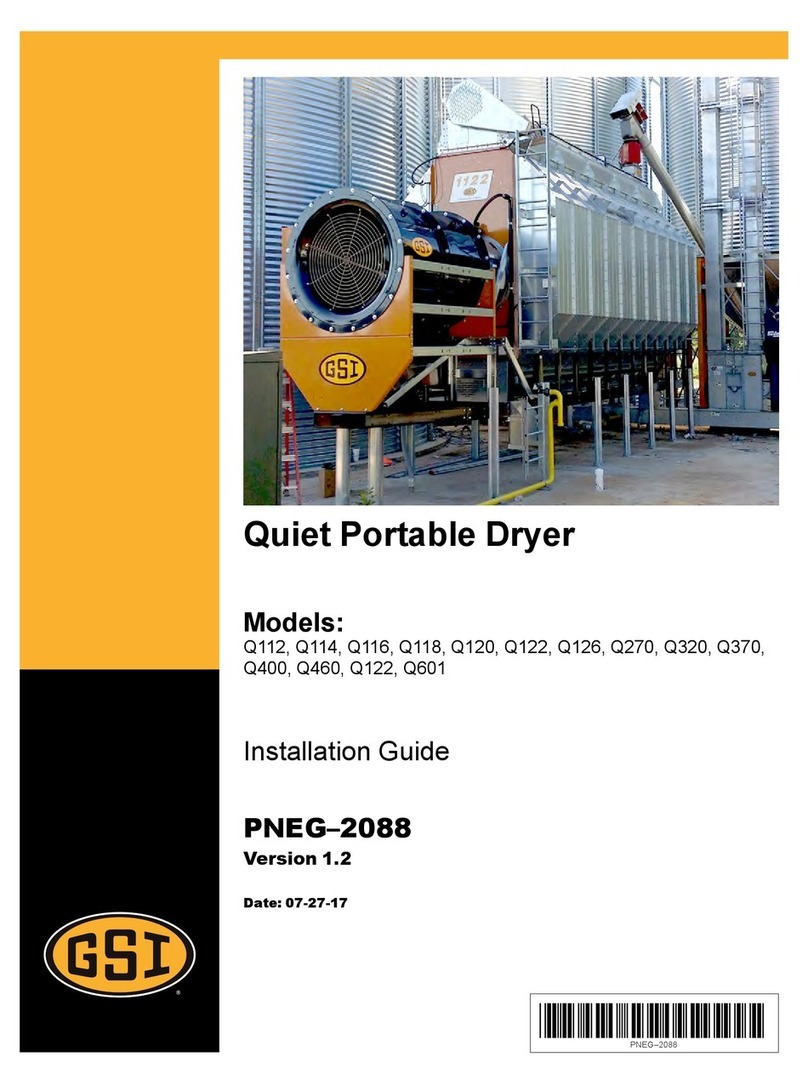
GSi 2314 User manual

PNEG-1622
2 and 3 Module Vision X-Stream
Portable Dryer
Operators Manual
PNEG-1622
Date: 04-17-14

2 PNEG-1622 2 and 3 Module Vision X-Stream Dryers

Table of Contents
PNEG-1622 2 and 3 Module Vision X-Stream Dryers 3
Contents
Chapter 1 Introduction ..........................................................................................................................................5
Dryer Operation ..................................................................................................................................... 5
Operating Precautions .......................................................................................................................... 5
Chapter 2 Safety .....................................................................................................................................................7
Safety Guidelines .................................................................................................................................. 7
Emergency Stop Switch ........................................................................................................................ 8
Chapter 3 Safety Decals ........................................................................................................................................9
Chapter 4 Specifications .....................................................................................................................................13
Dryer Specifications ............................................................................................................................ 13
Dryer Foundation ................................................................................................................................ 15
Chapter 5 Vision Control Panel ..........................................................................................................................21
Control Power Switch .......................................................................................................................... 21
Fan Switch .......................................................................................................................................... 21
Heater Switch ...................................................................................................................................... 21
Load Auger Switch .............................................................................................................................. 22
Unload Switch ..................................................................................................................................... 22
Outside Light Switch ........................................................................................................................... 22
Start Switch ......................................................................................................................................... 22
Stop Switch ......................................................................................................................................... 22
Chapter 6 Vision Touch Screen Display ............................................................................................................23
Boot Screen ........................................................................................................................................ 23
Default Operation Screen .................................................................................................................... 23
Select Data Log Sample Time ............................................................................................................ 24
Optional Operation Screen .................................................................................................................. 25
Setting the Timers ............................................................................................................................... 26
Setting the Temperatures .................................................................................................................... 28
The Setup Screen ............................................................................................................................... 29
Viewing the Owners Manuals on the Display Screen ......................................................................... 32
Viewing the Dryer Shut Down History ................................................................................................. 33
Chapter 7 Test Firing ...........................................................................................................................................34
Dryer Pre-Season Checks .................................................................................................................. 34
Inspect the Metering Rolls ................................................................................................................... 34
Check Control Panel Switches ............................................................................................................ 34
Electrical Power .................................................................................................................................. 34
Control Power Switch .......................................................................................................................... 34
Start Switch ......................................................................................................................................... 34
Fuel Check .......................................................................................................................................... 34
Load Auger .......................................................................................................................................... 35
Unload Auto Operation ........................................................................................................................ 35
Unload Manual Operation ................................................................................................................... 35
Meter Roll Operation ........................................................................................................................... 35
Fan Switches ....................................................................................................................................... 35
Burner Safety ...................................................................................................................................... 36
Burner Test Fire .................................................................................................................................. 36
Dryer Shut Down ................................................................................................................................. 38
Emergency .......................................................................................................................................... 38

Table of Contents
4PNEG-1622 2 and 3 Module Vision X-Stream Dryers
Chapter 8 Dryer Operation ..................................................................................................................................39
Dryer Start-Up and Operation Full Heat Drying .................................................................................. 39
Drying Temperatures .......................................................................................................................... 39
Dryer Shut Down ................................................................................................................................. 39
Initial Setup Parameters ...................................................................................................................... 39
Timer and Delay Settings .................................................................................................................... 39
Setting the Temperatures .................................................................................................................... 40
Start-Up ............................................................................................................................................... 40
Continuous Flow Drying Mode Using Regulation of Grain Temperature ............................................ 41
Continuous Flow Drying Mode using Regulation of Moisture: 5 MR SP ............................................. 48
Continuous Flow Drying Mode using Regulation of Moisture: Variable MR Speed ............................ 52
Chapter 9 Drying Time Tables ............................................................................................................................54
2000 Series Continuous Flow Full Heat .............................................................................................. 54
2000 Series Continuous Flow Dry and Cool ....................................................................................... 54
3000 Series Continuous Flow Full Heat .............................................................................................. 55
3000 Series Continuous Flow Dry and Cool ....................................................................................... 55
Chapter 10 Illustration .........................................................................................................................................56
Supply Line (LP Shown) .................................................................................................................... 56
LP Fan/Heater Pipe Train .................................................................................................................. 57
LP Vaporizer Coil Adjustment ............................................................................................................ 58
NG Fan/Heater Pipe Train ................................................................................................................. 58
Fan/Heater Control Box ..................................................................................................................... 59
Top Auger Drive ................................................................................................................................ 59
Discharge Safety Switch .................................................................................................................... 60
Meter Roll Speed Sensor .................................................................................................................. 60
Upper Control Box ............................................................................................................................. 61
Control Panel (Rear) .......................................................................................................................... 62
Lower Control Box (Back Panel) ....................................................................................................... 63
Chapter 11 Service ...............................................................................................................................................64
Seasonal Inspection and Service ...................................................................................................... 64
Lubrication Procedure ....................................................................................................................... 65
Fan Blade Removal and Installation .................................................................................................. 66
Removing the Fan Blade Assembly .................................................................................................. 66
Installing the Fan Blade Assembly .................................................................................................... 67
Fan Motor Removal ........................................................................................................................... 70
Heater Parts Removal and Installation .............................................................................................. 71
Metering Roll Servicing ...................................................................................................................... 71
Main Controls .................................................................................................................................... 72
How to Clear a Jammed Metering Roll .............................................................................................. 72
Fan and Heater Generated Errors ..................................................................................................... 73
Input/Output Generated Errors .......................................................................................................... 75
Master Display Generated Errors ...................................................................................................... 76
Vision Diagnostics ............................................................................................................................. 78
Display Input/Output Testing ............................................................................................................. 78
Air Switch ........................................................................................................................................... 79
Metering Rolls .................................................................................................................................... 80
Chapter 12 Warranty ............................................................................................................................................81
PNEG-1622 2 and 3 Module Vision X-Stream Dryers 5
1. Introduction
Dryer Operation
Thank you for choosing a GSI Vision X-Stream Series Grain Dryer. These units are among the finest
grain dryers ever built; designed to give you excellent operating performance and reliable service for
many years.
This manual describes the installation and operation for all standard production model dryers. These
dryers are available with liquid propane or natural gas fuel supply, single phase 230 volt, three phase
230 or 460 volt (60 Hz) electrical power.
Our foremost concern is your safety and the safety of others associated with this equipment. We want to
keep you as a customer. This manual is to help you understand safe operating procedures and some
problems which may be encountered by the operator and other personnel.
As owner and/or operator, it is your responsibility to know what requirements, hazards and precautions
exist, and to inform all personnel associated with the equipment or in the area. Safety precautions may be
required from the personnel. Avoid any alterations to the equipment. Such alterations may produce a very
dangerous situation where SERIOUS INJURY or DEATH may occur.
This equipment shall be installed in accordance with the current installation codes and applicable
regulations which should be carefully followed in all cases. Authorities having jurisdiction should be
consulted before installations are made.
Operating Precautions
READ THESE INSTRUCTIONS BEFORE INSTALLATION AND OPERATION
SAVE FOR FUTURE REFERENCE
1.Read and understand the operation manual before attempting to operate the unit.
2. Keep ALL guards, safety decals and safety devices in place. NEVER operate dryer while guards
are removed.
3. Keep visitors, children and untrained personnel away from dryer at all times.
4. NEVER attempt to operate the dryer by jumping or otherwise bypassing any safety devices on
the unit.
5. Always set the main power supply disconnect switch to OFF and lock it in the OFF position using
a padlock before performing any service or maintenance work on the dryer or the auxiliary
conveyor equipment.
6. Before attempting to remove and reinstall the fan blade, make certain to read recommended
procedure listed within the SERVICING section on Page 67 of the manual.
7. Keep the dryer and wet holding equipment CLEAN. DO NOT allow fine material to accumulate.
8. Set pressure regulator to avoid excessive gas pressure applied to a burner during ignition and when
burner is in operation. See Page 30 for operating gas pressures. DO NOT exceed maximum
recommended drying temperatures.
9. DO NOT operate the dryer if any gas leak is detected. Shut down and repair before further operation.
10. Clean grain is safer and easier to dry. Fine material can be highly combustible and it also requires
removal of extra moisture.
11. Use CAUTION in working around high-speed fans, gas burners, augers and auxiliary conveyors
which can START AUTOMATICALLY.

1. Introduction
6 PNEG-1622 2 and 3 Module Vision X-Stream Dryers
Operating Precautions (Continued)
12. Be certain that capacities of auxiliary conveyors are matched to dryer auger capacities.
13. Do not operate in an area where combustible material will be drawn into the fan.
14. The operating and safety recommendations in this manual pertain to the common cereal grains as
indicated. Whendrying any other grainor products, consult the factory for additional recommendations.
15. Routinely check for any developing gas plumbing leaks. Check LP vaporizer for contact with
burner vanes.
Use Caution in the Operation of this Equipment
This dryer is designed and manufactured with operator safety in mind. However, the very nature
of a grain dryer having a gas burner, high voltage electrical equipment and high speed rotating parts,
presents hazards to personnel which cannot be completely safeguarded against without interfering with
the efficient operation of the dryer and reasonable access to its components.
Use extreme caution in working around high speed fans, gas-fired heaters, augers and auxiliary
conveyors, which may start without warning when the dryer is operating on automatic control.
Continued safe, dependable operation of automatic equipment depends, to a great degree, upon the
owner. For a safe and dependable drying system, follow the recommendations within the Owner’s Manual
and make it a practice to regularly inspect the unit for any developing problems or unsafe conditions.
Take special note of the Operating Precautions on Page 5 before attempting to operate the dryer.
CAUTION
Keep the dryer clean. Do not allow fine material to accumulate in the plenum
chamber or surrounding the outside of the dryer.

PNEG-1622 2 and 3 Module Vision X-Stream Dryers 7
2. Safety
Safety Guidelines
This manual contains information that is important for you, the owner/operator, to know and understand.
This information relates to protecting personal safety and preventing equipment problems. It is the
responsibility of the owner/operator to inform anyone operating or working in the area of this equipment of
these safety guidelines. To help you recognize this information, we use the symbols that are defined
below. Please read the manual and pay attention to these sections. Failure to read this manual and its
safety instructions is a misuse of the equipment and may lead to serious injury or death.
DANGER
WARNING
CAUTION
NOTICE
This is the safety alert symbol. It is used to alert you
to potential personal injury hazards. Obey all safety
messages that follow this symbol to avoid possible
injury or death.
WARNING indicates a hazardous situation which, if not
avoided, could result in death or serious injury.
CAUTION, used with the safety alert symbol, indicates a
hazardous situation which, if not avoided, could result in
minor or moderate injury.
NOTICE is used to address practices not related to
personal injury.
DANGER indicates a hazardous situation which, if not
avoided, will result in death or serious injury.
Personnel operating or working around electric fans should read this manual. This manual
must be delivered with the equipment to its owner. Failure to read this manual and its
safety instructions is a misuse of the equipment.
WARNING! BE ALERT!

2. Safety
8 PNEG-1622 2 and 3 Module Vision X-Stream Dryers
Emergency Stop Switch
The Emergency Stop switch is located on the upper control box door. Pushing the Emergency Stop switch
will interrupt the control power and stop all dryer functions.
WARNING
Pushing the Emergency Stop switch does not interrupt the main power to the
upper control box panel.

PNEG-1622 2 and 3 Module Vision X-Stream Dryers 9
3. Safety Decals
The GSI Group, Inc. recommends contacting your local power company and having a representative
survey your installation, so the wiring is compatible with their system and adequate power is supplied to
the unit. Safety decals should be read and understood by all people in the grain handling area.
If a decal is damaged or is missing contact:
GSI Decals
1004 E. Illinois St.
Assumption, IL 62510
Phone: 1-217-226-4421
A free replacement will be sent to you.
DANGER
DANGER
DC-1224
High voltage.
Will cause serious
injury or death.
Lockout power
before servicing.
DANGERDANGER
HIGH VOLTAGE
Will cause injury
or death.
Lockout power
before servicing.
DC-889
GSI Group Inc. 217-226-4421
Decal: DC-889
Decal DC-889 has two (2) locations. One inside
the fan/heater control box and another on the
dryer upper control box door next to the main
power disconnect.
Decal: DC-1224
Decal DC-1224 is located in two (2) places on the fan/heater control box.
One on the lid and one on the front of the fan heater control box.
Another location for this decal is inside the upper control box for the dryer.

3. Safety Decals
10 PNEG-1622 2 and 3 Module Vision X-Stream Dryers
DC-972
WARNING
Moving parts can crush
and cut. Keep hands
clear. Do not operate
without guards in place.
Failure to do so could
result in serious injury.
GSI Group 217-226-4421
DANGERDANGER
Rotating auger will crush
and cut. Auto equipment
can start at anytime. Do not
enter until electric power is
locked in off position. Failure
to do so will result in serious
injury or death.
GSI Group 217-226-4421 DC-974
Automatically controlled
belt drive can start at
anytime. Keep hands
clear. Failure to do so
could result in serious
injury.
GSI Group 217-226-4421
DC-971
WARNING
Decal: DC-972
Decal DC-972 is located on the bottom auger belt guard and the front bearing
plate (which is visible when the bottom auger belt guard is removed).
An alternate location would be at the rear of the dryer for portable dryers
equipped with the Front Discharge Option.
Decal: DC-971
Decal DC-971 is located on the bottom auger belt guard and the front bearing plate
(which is visible when the bottom auger belt guard is removed). An alternate location
would be at the rear of the dryer for portable dryers equipped with the
Front
Discharge Option
.
Another location for decal DC-971 is on the top of the auger belt guard (one on the
belt guard cover and one on the inside belt guard body visible when the belt guard
cover is removed).
Decal: DC-974
Decal DC-974 has several different locations. Two (2) are located on the front end
panel below the fan/heater. Two (2) are located on the rear end panel below the rear
access door. Two (2) are located on the auger discharge box (one on the outside top
and one on the inside of the flapper lid next to the discharge mercury switch). One
more of these decals is located inside the plenum on the rear plenum closure door
just inside the rear access door.

3. Safety Decals
PNEG-1622 2 and 3 Module Vision X-Stream Dryers 11
Automatic equipment can
start at any time. Do not
enter until fuel is shut off
and electrical power is
locked in off position.
Failure to do so will result
in serious injury or death.
DC-973
DANGER
DANGER
GSI Group 217-226-4421
Flame and pressure beyond
door. Do not operate with
service door removed. Keep
head and hands clear. Can
cause serious injury.
DC-1227
WARNING
GSI Group 217-226-4421
DC-1229
WARNING
Rotating metering roll.
Equipment can start
automatically. Keep hands
clear. Can cause serious
injury. Disconnect power
before servicing.
Decal: DC-1229
Decal DC-1229 is located on each of
the meter roll access doors.
Decal: DC-973
Decal DC-973 is located on the rear plenum access door (inside
and outside).
Decal: DC-1227
Decal DC-1227 is located on the
fan/heater access door.

3. Safety Decals
12 PNEG-1622 2 and 3 Module Vision X-Stream Dryers
DC-1225
Stay clear of rotating
blade. Blade could start
automatically. Can cause
serious injury. Disconnect
power before servicing.
DC-1225GSI Group 217-226-4421
WARNING
16-17"
3/4" MINIMUM
BOLT DIAMETER
DC-388
Hitch pin must be
securely fastened and
no less than 3/4" in
diameter. Failure to
follow installation
instructions may result
in property damage.
DC-1249
Dryer must be
towed empty and
in accordance
with state and
provincial
regulations.
HUB TEMPERATURE
TIGHTEN TO
90FT-LBS.
55-60 PSI
COLD
CHECK AFTER 50 MILES AND EVERY 200 MILES
050
100 150 200 250
NO GREATER THAN 150°F
150°
Decal: DC-388
Decal DC-388 is located on the
hitch tongue.
Decal: DC-1249
Decal DC-1249 is located on the
hitch tongue.
Decal: DC-1225
Decal DC-1225 is located on the
fan/heater access door.

PNEG-1622 2 and 3 Module Vision X-Stream Dryers 13
4. Specifications
Dryer Specifications
2300 Series Dryer Specifications
2400 Series Dryer Specifications
2314 2318 2320 2322 2326
Total Holding Capacity (Bushels) 731 940 1044 1149 1304
Grain Column Holding Capacity (Bushels) 679 873 970 1067 1261
Fans 28'' 10-13 HP
40” 15 HP 36'' 10-12 HP
42” 20 HP 36’’ 15 HP
42’’ 25 HP 36'' 15 HP
42’’ 30 HP 40'' 25 HP
42’’ 40 HP
Top Auger 8'' Dia. 5 HP 8'' Dia. 5 HP 8'' Dia. 7.5 HP 8'' Dia. 7.5 HP 8'' Dia. 10 HP
Capacity (BHP) 3800 3800 3800 3800 3800
Bottom Auger 8'' Dia. 5 HP 8'' Dia. 5 HP 8'' Dia. 7.5 HP 8'' Dia. 7.5 HP 8'' Dia. 10 HP
Meter Roll Drive SCR, 3/4 HP SCR, 3/4 HP SCR, 3/4 HP SCR, 3/4 HP SCR, 3/4 HP
Capacity - Maximum Rate1(BHP) 1960 2520 2800 3080 3640
Electrical Load (Fans, Top and Bottom Augers2)
1 Phase, 220 Volt 226 -- -- -- --
3 Phase, 220 Volt 121 132 182 192 282
3 Phase, 440 Volt 61 66 91 96 141
3 Phase, 575 Volt 49 53 73 77 113
1Actual discharge rate is controll by meter roll speed adjustment at 5 % to 100 % of maximum rate.
2Excludes auxiliary load and unload conveyor equipment.
2414 2418 2420 2422 2426
Total Holding Capacity (Bushels) 731 940 1044 1149 1304
Grain Column Holding Capacity (Bushels) 679 873 970 1067 1261
Fans 28'' 10-13 HP
28'' 10-13 HP 36'' 10-12 HP
36'' 10-12 HP 36’’ 15 HP
36’’ 15 HP 36'' 15 HP
36’’ 15 HP 40'' 25 HP
40'' 25 HP
Top Auger 8'' Dia. 5 HP 8'' Dia. 5 HP 8'' Dia. 7.5 HP 8'' Dia. 7.5 HP 8'' Dia. 10 HP
Capacity (BHP) 3800 3800 3800 3800 3800
Bottom Auger 8'' Dia. 5 HP 8'' Dia. 5 HP 8'' Dia. 7.5 HP 8'' Dia. 7.5 HP 8'' Dia. 10 HP
Meter Roll Drive SCR, 3/4 HP SCR, 3/4 HP SCR, 3/4 HP SCR, 3/4 HP SCR, 3/4 HP
Capacity - Maximum Rate1(BHP) 1960 2520 2800 3080 3640
Electrical Load (Fans, Top and Bottom Augers2)
1 Phase, 220 Volt 244 244 -- -- --
3 Phase, 220 Volt 138 138 196 196 308
3 Phase, 440 Volt 69 69 98 98 154
3 Phase, 575 Volt 55 55 78 78 123
1Actual discharge rate is controll by meter roll speed adjustment at 5 % to 100 % of maximum rate.
2Excludes auxiliary load and unload conveyor equipment.

4. Specifications
14 PNEG-1622 2 and 3 Module Vision X-Stream Dryers
3400 Series Dryer Specifications
3600 Series Dryer Specifications
3414 3418 3420 3422 3426
Total Holding Capacity (Bushels) 1074 1381 1534 1688 1995
Grain Column Holding Capacity (Bushels) 1022 1314 1460 1606 1898
Fans 28'' 10-13 HP
40'' 15 HP 36'' 10-12 HP
42'' 20 HP 36’’ 15 HP
42’’ 25 HP 36'' 15 HP
42’’ 30 HP 40'' 25 HP
42'' 40 HP
Top Auger 8'' Dia. 5 HP 8'' Dia. 5 HP 8'' Dia. 7.5 HP 8'' Dia. 7.5 HP 8'' Dia. 10 HP
Capacity (BHP) 3800 3800 3800 3800 3800
Bottom Auger 8'' Dia. 5 HP 8'' Dia. 5 HP 8'' Dia. 7.5 HP 8'' Dia. 7.5 HP 8'' Dia. 10 HP
Meter Roll Drive SCR, 3/4 HP SCR, 3/4 HP SCR, 3/4 HP SCR, 3/4 HP SCR, 3/4 HP
Capacity - Maximum Rate1(BHP) 1960 2520 2800 3080 3640
Electrical Load (Fans, Top and Bottom Augers2)
1 Phase, 220 Volt 304 -- -- -- --
3 Phase, 220 Volt 160 182 246 266 384
3 Phase, 440 Volt 80 91 123 133 192
3 Phase, 575 Volt 64 73 98 106 154
1Actual discharge rate is controll by meter roll speed adjustment at 5% to 100% of maximum rate.
2Excludes auxiliary load and unload conveyor equipment.
3614 3618 3620 3622 3626
Total Holding Capacity (Bushels) 1074 1381 1534 1688 1995
Grain Column Holding Capacity (Bushels) 1022 1314 1460 1606 1898
Fans 28'' 10-13 HP 36'' 10-13 HP 36’’ 15 HP 36'' 15 HP 40'' 25 HP
Top Auger 8'' Dia. 5 HP 8'' Dia. 5 HP 8'' Dia. 7.5 HP 8'' Dia. 7.5 HP 8'' Dia. 10 HP
Capacity (BHP) 3800 3800 3800 3800 3800
Bottom Auger 8'' Dia. 5 HP 8'' Dia. 5 HP 8'' Dia. 7.5 HP 8'' Dia. 7.5 HP 8'' Dia. 10 HP
Meter Roll Drive SCR, 3/4 HP SCR, 3/4 HP SCR, 3/4 HP SCR, 3/4 HP SCR, 3/4 HP
Capacity - Maximum Rate1(BHP) 1960 2520 2800 3080 3640
Electrical Load (Fans, Top and Bottom Augers2)
1 Phase, 220 Volt 340 340 -- -- --
3 Phase, 220 Volt 194 194 274 274 436
3 Phase, 440 Volt 97 97 137 137 218
3 Phase, 575 Volt 78 78 110 110 174
1Actual discharge rate is controll by meter roll speed adjustment at 5 % to 100 % of maximum rate.
2Excludes auxiliary load and unload conveyor equipment.

4. Specifications
PNEG-1622 2 and 3 Module Vision X-Stream Dryers 15
Dryer Foundation
Figure 4A Foundation Plan View and Foundation Cross Section
Stack Dryer Foundation
Minimum soil bearing capacity = 2000 PSF.
Basket Length 14 18 20 22 26
Concrete Pad Size (12’ x “X”)112 x 27 12 x 31 12 x 33 12 x 35 12 x 39
Concrete (cubic yards) 25 27 30 32 35
#4 Rebar (feet)21040 1200 1270 1350 1500
Anchors316 20 22 24 28
11 0” depth with 36” wide x 36” deep footings along each side
2#4 reinforcing rods on 1’ - 0” centers. Both directions in slab and bottom of footing.
3Use 3/4” x 9 5/8” minimum anchors with epoxy. GSI part numbers: anchor (GTC-0003) epoxy (GTC-0004)

4. Specifications
16 PNEG-1622 2 and 3 Module Vision X-Stream Dryers
Concrete Specifications:
• Compressive Strength @ 28 days -- 4000 PSI
• Minimum Cement Content -- 6 sacks/yard.
• Maximum slump -- 4" +/- 1".
Figure 4B Example of Stack Dryer Footprint

4. Specifications
18 PNEG-1622 2 and 3 Module Vision X-Stream Dryers
Figure 4D 2 Module Stack Dryer Dimension

4. Specifications
20 PNEG-1622 2 and 3 Module Vision X-Stream Dryers
Figure 4F 3 Module Stack Dryer Dimensions
This manual suits for next models
19
Table of contents
Other GSi Dryer manuals
Popular Dryer manuals by other brands

Maytag
Maytag W10057351A Use and care guide

Frigidaire
Frigidaire AEQ7000CES0 installation instructions

Bosch
Bosch WTW87565AU Installation and operating instructions

GE
GE Appliances Profile PFDS450 Owner's manual and installation instructions

Hotpoint Ariston
Hotpoint Ariston AAQCF81U IT Service information

Zanussi
Zanussi TD260 Instruction booklet