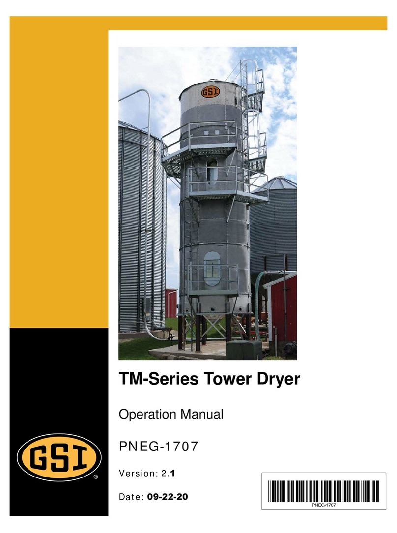
GSi Domestic - Mod/T User manual

PNEG-2075
Modular Tower Dryer
Wiring Diagrams
Model:
Domestic - Mod/T and F
Electrical Installation Manual
PNEG-2075
Version: 1.2
Date: 09-22-20

2 PNEG-2075 Modular Tower Dryer Wiring Diagrams for Domestic
All information, illustrations, photos and specifications in this manual are based on the latest
information available at the time of publication. The right is reserved to make changes at any
time without notice.

Table of Contents
PNEG-2075 Modular Tower Dryer Wiring Diagrams for Domestic 3
Contents
Chapter 1 Safety ..................................................................................................................................................... 4
Safety Guidelines .................................................................................................................................. 4
Cautionary Symbols Definitions ............................................................................................................ 5
Safety Cautions ..................................................................................................................................... 6
Safety Sign-Off Sheet ......................................................................................................................... 11
Chapter 2 Domestic Mod Wiring Diagrams ....................................................................................................... 14
Domestic ACL Mod/T and F Dryers (Page 1) ..................................................................................... 14
Domestic Soft Start Mod/T and F Panel Layout (Page 1) ................................................................... 16
Domestic Mod/T and F Dryers Notes (Page 2) ................................................................................... 18
Domestic Mod/T and F Dryers Terminal Strip Function (Page 3) ....................................................... 19
Domestic Mod Field Installation Marks (Page 4) ................................................................................. 20
Domestic Mod/T and F Dryer Switch I/O Connections (Page 5) ......................................................... 21
Domestic Mod Dryer ACL with High-Low (Page 6) ............................................................................. 22
Domestic Mod Dryer ACL with Modulating Valve (Page 6) ................................................................. 23
Domestic Mod Dryer Soft Start with Modulating Valve (Page 6) ......................................................... 24
Domestic Mod Dryer Soft Start with High-Low Valve (Page 6) ........................................................... 25
Domestic Mod Dryer ACL with High-Low Valve (Page 7) ................................................................... 26
Domestic Mod Dryer ACL with Modulating Valve (Page 7) ................................................................. 27
Domestic Mod Dryer Soft Start with Modulating Valve (Page 7) ......................................................... 28
Domestic Mod Dryer Soft Start with High-Low Valve (Page 7) ........................................................... 29
Domestic Mod Dryer ACL with High-Low Valve (Page 8) ................................................................... 30
Domestic Mod Dryer ACL with Modulating Valve (Page 8) ................................................................. 31
Domestic Mod Dryer Soft Start with Modulating Valve (Page 8) ......................................................... 32
Domestic Mod Dryer Soft Start with High-Low Valve (Page 8) ........................................................... 33
Chapter 3 Domestic T and F Wiring Diagrams .................................................................................................. 36
Domestic ACL Mod/T and F Dryers (Page 1) ..................................................................................... 36
Domestic Soft Start Mod/T and F Panel Layout (Page 1) ................................................................... 38
Domestic Mod/T and F Dryers Notes (Page 2) ................................................................................... 40
Domestic Mod/T and F Dryers Terminal Strip Function (Page 3) ....................................................... 41
Domestic T and F Field Installation Marks (Page 4) ........................................................................... 42
Domestic Mod/T and F Dryer Switch I/O Connections (Page 5) ......................................................... 43
Domestic T and F Dryer ACL with Modulating Valve (Page 6) ........................................................... 44
Domestic T and F Dryer ACL with High-Low Valve (Page 6) .............................................................. 45
Domestic T and F Dryer Soft Start with High-Low (Page 6) ................................................................ 46
Domestic T and F Dryer Soft Start with Modulating Valve (Page 6) ................................................... 47
Domestic T and F Dryer ACL with Modulating Valve (Page 7) ........................................................... 48
Domestic T and F Dryer ACL with High-Low Valve (Page 7) .............................................................. 49
Domestic T and F Dryer Soft Start with High-Low Valve (Page 7) ...................................................... 50
Domestic T and F Dryer Soft Start with Modulating Valve (Page 7) ................................................... 51
Domestic T and F Dryer ACL with Modulating Valve (Page 8) ........................................................... 52
Domestic T and F Dryer ACL with High-Low Valve (Page 8) .............................................................. 53
Domestic T and F Dryer Soft Start with High-Low Valve (Page 8) ...................................................... 54
Domestic T and F Dryer Soft Start with Modulating Valve (Page 8) ................................................... 55
Chapter 4 Warranty .............................................................................................................................................. 57

4 PNEG-2075 Modular Tower Dryer Wiring Diagrams for Domestic
1. Safety
Safety Guidelines
Safety guidelines are general-to-specific safety rules that must be followed at all times. This manual is
written to help you understand safe operating procedures and problems that can be encountered by the
operator and other personnel when using this equipment. Save these safety guidelines for future
reference.
As owner or operator, you are responsible for understanding the requirements, hazards, and precautions
that exist and to inform others as required. Unqualified persons must stay out of the work area at all times.
Alterations must not be made to the equipment. Alterations can produce dangerous situations resulting in
SERIOUS INJURY or DEATH.
This equipment must be installed in accordance with the current installation codes and applicable
regulations,whichmustbecarefully followed inall cases. Authoritieshavingjurisdiction mustbe consulted
before installations are made.
When necessary, you must consider the installation location relative to electrical, fuel and water utilities.
Personnel operating or working around equipment must read this manual. This manual must be delivered
with equipment to its owner. Failure to read this manual and its safety instructions is a misuse of the
equipment.
ST-0001-3

1. Safety
PNEG-2075 Modular Tower Dryer Wiring Diagrams for Domestic 5
Cautionary Symbols Definitions
Cautionary symbols appear in this manual and on product decals. The symbols alert the user of potential
safety hazards, prohibited activities and mandatory actions. To help you recognize this information, we
use the symbols that are defined below.
DANGER
WARNING
CAUTION
NOTICE
This symbol indicates an imminently hazardous situation
which, if not avoided, will result in serious injury or death.
This symbol indicates a potentially hazardous situation
which, if not avoided, can result in serious injury or death.
This symbol indicates a potentially hazardous situation which,
if not avoided, can result in minor or moderate injury.
This symbol is used to address practices not related to
personal injury.
This symbol indicates a general hazard.
This symbol indicates a prohibited activity.
This symbol indicates a mandatory action.
ST-0005-2

1. Safety
6 PNEG-2075 Modular Tower Dryer Wiring Diagrams for Domestic
Safety Cautions
Use Personal Protective Equipment
Eye
Protection
Hearing
Protection
Hand
Protection
Head
Protection
Respiratory
Protection Foot
Protection
Fall
Protection
• Use appropriate personal protective equipment:
• Wear clothing appropriate to the job.
• Remove all jewelry.
• Tie long hair up and back.
ST-0004-1
Follow Safety Instructions
• Warning: If the information in the manual is not followed
exactly, a fire or explosion can result, causing property
damage, personal injury or loss of life.
• Carefully read all safety messages in this manual and
safety signs on your machine. Keep signs in good
condition. Replace missing or damaged safety signs. Be
sure new equipment components and repair parts include
the current safety signs. Replacement safety signs are
available from the manufacturer.
• Learn how to operate the machine and how to use controls
properly. Do not let anyone operate without instruction.
• If you do not understand any part of this manual or need
assistance, contact your dealer.
ST-0025-2
Install and Operate Equipment Properly
• Before attempting to remove and re-install the fan blade,
contact GSI for the recommended procedure.
ST-0033-2

1. Safety
PNEG-2075 Modular Tower Dryer Wiring Diagrams for Domestic 7
Install and Operate Gas-Fired Equipment Properly
• Gas-fired equipment should be installed by a qualified pipe
fitter and must conform with local codes.
• For Canada: The equipment shall be installed in accordance
with the Natural Gas and Propane Installation Code, CSA
B149.1, or the Propane Storage and Handling Code, CSA
B149.2, or applicable provincial regulations, which should be
carefully followed in all cases. Authorities having jurisdiction
should be consulted before installations are made.
• For the United States: The equipment shall be installed in
accordance with the National Fuel Gas Code ANSI
Z223.1/NFPA 54.
ST-0016-2
For Your Safety
• If you smell gas:
- Do not try to light any appliance.
- Extinguish any open flames.
- Do not touch any electrical switch.
- Immediately call your gas supplier. Follow the gas supplier’s
instructions.
- If you cannot reach your gas supplier, call the fire department.
• The use and storage of gasoline and other flammable vapors and
liquids in open containers in the vicinity of this appliance is
hazardous.
• Improper installation, adjustment, alteration, service or maintenance
can cause property damage, injury or death. Read the installation,
operating and maintenance instructions thoroughly before installing
or servicing this equipment. Installation and service must be
performed by a qualified installer, service agency or the gas
supplier.
ST-0024-1
ST-0027-2
Install and Operate Electrical Equipment Properly
• Electrical controls must be installed by a qualified electrician
and must meet the standards set by applicable local codes
(National Electrical Code for the US, Canadian Electric Code,
or EN60204 along with applicable European Directives
for Europe).
• Lock-out power source before making adjustments, cleaning, or
maintaining equipment.
• Make sure all equipment and bins are properly grounded.

1. Safety
8 PNEG-2075 Modular Tower Dryer Wiring Diagrams for Domestic
Maintain Equipment and Work Area
• Understand service procedures before doing work.
• Keep area clean and dry.
• Do not service equipment while it is operating. Disconnect and
lock-out power and fuel supply before entering equipment or
before performing maintenance.
• Keep your equipment in proper working condition. Replace
worn or broken parts immediately.
• Depressurize the fuel train before disassembling for service.
• Allow the fan to operate for 20 minutes with the burner off to
purge products of combustion and to cool the components
before entering.
• Check regularly for any developing gas plumbing leaks. Do not
operate the dryer if any gas leak is detected. Shut down and
repair before further operation.
ST-0030-2
Exercise Caution When Drying Flammable Grains
• Be aware that some grains are highly flammable including but
not limited to rapeseed, canola, linseed, sunflower and milo.
• All grain and seed must be whole (minimal cracking or
crushing), clean and dust free before drying.
• Avoid dust and chaff from being drawn into the fan and heater.
• To reduce risk of fire, keep the fan, heater, drying plenum and
ducts clean at all times.
• In the event of a fire (or suspected fire):
1. Shut down the entire dryer.
2. Turn off fuel at the tank or supply valve.
3. Shut off and lock electrical power.
4. Evacuate the area.
5. Call the fire department.
ST-0032-1
Fall Hazard
• Keep access door closed while on a platform to avoid falls.
• Always use proper personal protective equipment and proper
clothing when using equipment. Failure to follow safety
precautions can result in severe injury or death.
ST-0042-2

1. Safety
PNEG-2075 Modular Tower Dryer Wiring Diagrams for Domestic 9
Maintain Equipment and Work Area
• Equipment is intended for the use of grain drying only. Any
other use is a misuse of this equipment.
• The operating instructions in this manual pertain to the
common cereal grains as indicated. When drying any other
grain, contact GSI for additional recommendations.
• Be certain that capacities of auxiliary conveyors are matched
to dryer metering capacities.
• On LP fired units, set pressure regulator to avoid excessive
gas pressure applied to the burner during ignition and
operation. Do not exceed maximum recommended
drying temperatures.
• Equipment has sharp edges that can cause serious injury. To
avoid injury, handle sharp edges with caution and use proper
protective clothing and equipment at all times.
• All guards must be in place before and during operation.
Images of guards removed in this manual are for illustration
purposes only.
• Use caution when working around high-speed fans, gas
burners, augers and auxiliary conveyors which can start
automatically.
• Keep hands, feet, and clothing away from moving parts.
• Do not bypass any safety device or interlock.
• Do not enter the dryer or bin while it is operating.
• Do not operate in an area where combustible material will be
drawn into the dryer.
ST-0034-2
Stay Clear of Hoisted Equipment
• Always use proper lifting or hoisting equipment when
assembling or disassembling equipment.
• Do not walk or stand under hoisted equipment.
• Always use sturdy and stable supports when needed for
installation. Not following these safety precautions creates
the risk of falling equipment, which can crush personnel and
cause serious injury or death.
ST-0047-1

1. Safety
10 PNEG-2075 Modular Tower Dryer Wiring Diagrams for Domestic
ST-0055-1
Confined Space Hazards and Entry Procedures
• Note that the interior of this equipment is considered a confined
space. Maintenance of this equipment can require access to the
confined space.
• Access doors must be shut and locked except when access is
required.
• Doors giving access to dangerous equipment must be safety
interlocked.
• The following entry procedures must be followed:
- Be aware of all possible hazards present inside the confined
space and wear personal protective equipment (PPE) as needed.
- Complete a permit to work and follow all permit required confined
space entry procedures defined by the site manager.
- Make sure that the area has been purged of any hazardous
productsorgases.Checktheatmosphereforharmfulgases
orvapors with asuitable gasanalyzer andmake surelevels
are safe before entering.
- Do not smoke or use naked flames.
- Lock out and tag out power supplies and fuel supplies to
all equipment.
- Do not work alone. Work in teams of at least three so that help
is immediately available in the event of an emergency.
- Confirm that all personnel have safely exited the equipment
and tools have been recovered once work is complete.
Fall Hazard
• Ladders, stairways and platforms are for use by competent
and trained personnel only. Do not allow children or other
unauthorized persons to have access to the equipment.
• Access to the equipment must be restricted by the use of
security fencing and lockable gates.
• Lower sections of ladders must be fitted with a lockable safety
gate to prevent unauthorized access.
• Make sure that hot surfaces have had adequate time to cool
before working on or in the equipment.
• Lock out and tag out power supplies and fuel supplies to all
equipment.
• Do not attach lifting equipment to ladders or platforms.
• Do not go outside of the safety rails provided on elevated
platforms.
• Do not work at heights during high winds, rain, snow, or ice
storms.
ST-0056-1

1. Safety
PNEG-2075 Modular Tower Dryer Wiring Diagrams for Domestic 11
Safety Sign-Off Sheet
Below is a sign-off sheet thatcan be used to verify that all personnel have read and understood the safety
instructions. This sign-off sheet is provided for your convenience and personal record keeping.
Date Employee Name Supervisor Name
ST-0007

12 PNEG-2075 Modular Tower Dryer Wiring Diagrams for Domestic
NOTES

®
PNEG-2075 Modular Tower Dryer Wiring Diagrams for Domestic 13
Domestic Mod
Wiring Diagrams

14 PNEG-2075 Modular Tower Dryer Wiring Diagrams for Domestic
2. Domestic Mod Wiring Diagrams
Domestic ACL Mod/T and F Dryers (Page 1)
Figure 2A
14 15 16 17 18
1
2
3
4
5
1
6
13
1
1
1
12
11
10
8
7
9
AIRSWITCH
D03-0723
VFD LINE REACTOR
CONTROL RELAY 1
FAN/HEATER
BOARD
IGNITION
X-FORMER
BURNER
CONTROL
UNIT
L
O
R
T
NOC
R
E
MR
OF
-X
MAIN I/O
BOARD
FAN 1 STARTER
2T1
4T2 6T3
A1
1L13L2 5L3
A2
14
13
NO xxHP
xxA
xxxV
9695

2. Domestic Mod Wiring Diagrams
PNEG-2075 Modular Tower Dryer Wiring Diagrams for Domestic 15
Domestic ACL Mod/T and F Dryers
Ref # Description
1GND Lug
2Breaker
3Distribution Block (GT3-0484)
4Control X-Former
5Motor Starter
6Fan/Heater Board (D03-0723)
7PLC
8Main I/O Board
9Burner Control Unit
10 Ignition X-Former
11 Airswitch
12 VFD Line Reactor
13 VFD
14 VFD C/B
15 Load Starter
16 Unload Starter
17 Power C/B
18 Control X-Former C/B

2. Domestic Mod Wiring Diagrams
16 PNEG-2075 Modular Tower Dryer Wiring Diagrams for Domestic
Domestic Soft Start Mod/T and F Panel Layout (Page 1)
Figure 2B
14 15 16 17 18
1
2
3
4
5
1
6
13
11
1
12
11
10
8
7
9
SOFT-START
AIRSWITCH
D03-0723
VFD LINE REACTOR
CONTROL RELAY 1
CONTROL RELAY 2
FAN/HEATER
BOARD
IGNITION
X-FORMER
BURNER
CONTROL
UNIT
CONTROL
R
EMRO
F-
X
MAIN I/O
BOARD

2. Domestic Mod Wiring Diagrams
PNEG-2075 Modular Tower Dryer Wiring Diagrams for Domestic 17
Domestic Soft Start Mod/T and F Panel Layout
Ref # Description
1GND Lug
2Breaker
3Distribution Block (GT3-0484)
4Control X-Former
5Soft Start
6Fan/Heater Board (D03-0723)
7PLC
8Main I/O Board
9Burner Control Unit
10 Ignition X-Former
11 Airswitch
12 VFD Line Reactor
13 VFD
14 VFD C/B
15 Load Starter
16 Unload Starter
17 Power C/B
18 Control X-Former C/B

2. Domestic Mod Wiring Diagrams
18 PNEG-2075 Modular Tower Dryer Wiring Diagrams for Domestic
Domestic Mod/T and F Dryers Notes (Page 2)
Figure 2C
SUPPLY PROTECTION TO BE PROVIDED BY
CUSTOMER/INSTALLER
161514131211109
8
7
654321
1
0
DIP SWITCH SETTINGS
DRIVE PROGRAM- POWERFLEX 4M(DOM)
DIP SWITCH = 0-10V
DIP SWITCH = SRC
P103 = MOTOR FLA
P104 = SET TO 5.2 (MIN FREQ)
P105 = SET TO 60 (MAX FREQ)
P106 = SET TO 2 (2-WIRE)
P107 = 0 (RSMP STOP)
P108 = SET TO 2 (0-10V)
P109 = 10 (ACCL)
P110 = SET TO 1.0 (DECL)
ASSEMBLER & INSTALLER -
VERIFY XFMR CONFIG
A.
B.
C.
INSERT JUMPER BAR TERMINAL BETWEEN (7-10),
(14-20), (24-27) & (41-46)
D.
NOTES ARE NOT SHOWN IN
EXACT SCHEMATIC PAGES
19
14
13
H.
BLOWER SAMPLER 2KVA
TRANSFORMER WIRING
I.
GRAY
WHITE/BLACK STRIPE
BLUE
GREEN
RED
BROWN
PINK
PURPLE
YELLOW
ORANGE
BLACK
WHITE
COLOR LEGEND
5

2. Domestic Mod Wiring Diagrams
PNEG-2075 Modular Tower Dryer Wiring Diagrams for Domestic 19
Domestic Mod/T and F Dryers Terminal Strip Function (Page 3)
Figure 2D
11
22
33
44
55
66
77
88
99
10 10
11 11
12 12
13 13
14 14
15 15
16 16
17 17
18 18
19 19
20 20
21 21
22 22
23 23
24 24
25 25
26 26
27 27
28 28
29 29
30 30
31 31
32 32
33 33
34 34
35 35
36 36
37 37
38 38
39 39
40 40
AC1 - CONTROL PANEL CONNECTION
ACN - CONTROL PANEL CONNECTION
J6-01 - CONTROL PANEL CONNECTION
GND - CONTROL PANEL CONNECTION
LITE - CONTROL PANEL CONNECTION
J7-01 - CONTROL PANEL CONNECTION
BINDICATOR MOTOR 120V
TO VENT VALVE/LIQUID SOLENOID
CYCLE SOLENOID (N/A W/MODULATING)
BINDICATOR MOTOR NEUTRAL
CYCLE SOLENOID NEUTRAL
GAS VALVE NEUTRAL/LITE NEUTRAL
LITE
MJ7-01
GND
BINDICATOR (COM) +12 MAIN IO
+12V (MJ2-01)
+12V (MJ2-01)
DISCHARGE SWITCH (MJ1-08)
USER SAFETY #4 (MJ2-06)
USER SUPPLIED SAFETY (MJ2-04
AIR SYSTEM INTERLOCK (MJ1-10)
BINDICATOR (N/C)
-12V MAIN IO
GND
GRAIN TEMP (WHT)
GRAIN TEMP (BLK)
PLENUM TEMP (WHT)
PLENUM TEMP (BLK)
GND
GRAIN TEMP (WHT)
FROM ESTOP
FROM TRANSFORMER L-2 (ACN)
MJ6-01
GND
LITE
MJ7-01
MJ1-03
TO S.S. TERM A1 & 97
FJ1-01
FJ1-02
FJ1-04
BCM # X3-04/4
TO S.S. TERM A2
MJ6-02
MJ7-02
JUMPER TO TERM 5
JUMPER TO TERM 6
GND
MJ2-01
JUMPER TO TERM 31
JUMPER TO TERM 29 & 30
JUMPER TO TERM 28
MJ1-06
MJ2-06
MJ2-04
MJ1-10
MJ2-08
MJ2-10
GND
FJ3-04
FJ3-03
FJ3-02
FJ3-01
GND
FJ5-03
41 41
42 42
43 43
44 44
45 45
46 46
47 47
48 48
49 49
50 50
51 51
52 52
53 53
54 54
55 55
56 56
57 57
58 58
59 59
60 60
61 61
62 62
63 63
64 64
65 65
66 66
67 67
68 68
69 69
70 70
71 71
72 72
+12V FAN HEATER
AIRSWITCH COMMON
HOUSING HI-LIMIT
VAPOR HI-LIMIT & GAS
PRESSURE SWITCH COM
PLENUM HI-LIMIT
TOP OVERHEAT +12V
MID/TOP OVERHEAT TEST POINT (OR
OUTSIDE OVERHEAT-MOD'S)
HOUSING HI-LIMIT
PLENUM ADJUSTABLE HI-LIMIT
FROM HI-LIMIT (JUMP TO TERM 44 IF NOT L.P. FUEL
LOW GAS PRESSURE SWITCH (JUMP TO +12V IF NOT USED)
MID/BOTTOM OVERHEAT TEST POINT
BOTTOM OVERHEAT
AIRSWITCH N/O
HIGH GAS PRESSURE SWITCH (JUMP TO +12V IF NOT USED
GND
MODUTROL MOTOR "+"
MODUTROL MOTOR "-"
MAIN SOLENOID VALVES
MAIN SOLENOID VALVES NEUTRAL
BURNER FLAME ROD
BURNER GND
MOD VALVE SWITCH (JUMP TO 66 IF NO MOD VALVE)
MOD VALVE SWITCH (JUMP TO 65 IF NO MOD VALVE)
UV FLAME SENSOR (+) (T&F ONLY)
UV FLAME SENSOR (-) (T&F ONLY)
MAXON #1 TERMINAL #7
MAXON #1 TERMINAL #8
FJ4-01
(MOD'S ONLY FJ4-06)
(T&F ONLY FJ4-06)
FJ4-04
FJ4-09
FJ4-05
FJ4-07
FJ4-02
FJ4-08
GND
MOD BOARD POS.
MOD BOARD NEG.
X7-01/3 & J1-01
X7-01/2 (NEUTRAL)
X10-05/2
X10-05/1
BCM # X10-06/1
BCM # X10-06/2
EXTERNAL INTERNAL EXTERNAL INTERNAL
MAXON #2 TERMINAL #7
MAXON #2 TERMINAL #8
1."F" TERMINALS ON FAN/HEATER BOARD
2."M" TERMINALS ON MAIN I/O BOARD
3."X" TERMINALS ON SIEMENS BURNER CONTROL
NOTES:

2. Domestic Mod Wiring Diagrams
20 PNEG-2075 Modular Tower Dryer Wiring Diagrams for Domestic
Domestic Mod Field Installation Marks (Page 4)
Figure 2E
GRAIN TEMP THERMISTOR
PLENUM THERMISTOR
(* ONLY APPLICABLE IF EQUIPPED WITH MOD VALVE)
BURNER FLAME ROD
BURNER GROUND
T AND F - FIELD INSTALLATION MARKS PROVIDED BY INSTALLER
AUTOMATIC AIR SYSTEM- INTERPOSING RELAY INSTALLATION (RELAY NOT PROVIDED)
(* ONLY APPLICABLE IF EQUIPPED WITH MOD VALVE)
This manual suits for next models
2
Table of contents
Other GSi Dryer manuals