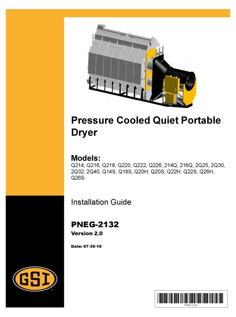
GSi TopDry Autoflow 2000 Series User manual

PNEG-696
TopDry Series 2000 Autoflow
Operation Manual
PNEG-696
Date: 09-27-20

2PNEG-696 TopDry Series 2000 Autoflow
All information, illustrations, photos and specifications in this manual are based on the latest
information available at the time of publication. The right is reserved to make changes at any
time without notice.

Table of Contents
PNEG-696 TopDry Series 2000 Autoflow 3
Contents
Chapter 1 Safety .....................................................................................................................................................5
Cautionary Symbols Definitions ............................................................................................................ 5
Fan/Heater Installation and Operating Instructions ............................................................................... 6
Safety Precautions ................................................................................................................................ 7
Safety Sign-Off Sheet ........................................................................................................................... 8
Chapter 2 Safety Decals ........................................................................................................................................9
Chapter 3 Electrical Power Supply .....................................................................................................................11
Power Supply ...................................................................................................................................... 11
Transformer and Wiring Voltage Drop ................................................................................................ 11
Machine to Earth Grounding ............................................................................................................... 11
Chapter 4 Control Panel ......................................................................................................................................12
Dryer Control Panel Featuring the Electronic Monitoring Control System .......................................... 13
Moisture Control Switch ...................................................................................................................... 13
Control Power Switch .......................................................................................................................... 13
Aeration Fan Switch ............................................................................................................................ 13
Load Auger Switch .............................................................................................................................. 13
Fan Switch .......................................................................................................................................... 14
Heater Switch ...................................................................................................................................... 14
Dump Switch ....................................................................................................................................... 14
Dry and Hold Switch ............................................................................................................................ 14
Dryer Power Start Switch .................................................................................................................... 14
Dryer Power Stop Switch .................................................................................................................... 14
Chapter 5 Control System ...................................................................................................................................15
Electronic Monitoring Control System ................................................................................................. 15
Turning On the Electronic Monitoring Control System ........................................................................ 15
Setting the Dry, Cool and Unload Timers ............................................................................................ 16
Setting the Delays ............................................................................................................................... 16
Set-Up: Standard ................................................................................................................................ 17
Set-Up: Extended ................................................................................................................................ 17
Plenum and Grain Temperature Settings, Screens Button Options .................................................... 19
Chapter 6 Fill System Control Box .....................................................................................................................20
Fill System #1 ...................................................................................................................................... 21
Fill System #2 ...................................................................................................................................... 21
Aeration Fan ........................................................................................................................................ 21
Emergency Stop Switch ...................................................................................................................... 21

Table of Contents
4PNEG-696 TopDry Series 2000 Autoflow
Chapter 7 Error Messages ..................................................................................................................................22
Burner 1 Loss Flame ........................................................................................................................... 22
Burner 2 Loss Flame ........................................................................................................................... 22
Fan 1 Vapor High-Limit ....................................................................................................................... 22
Fan 2 Vapor High-Limit ....................................................................................................................... 22
Fan 1 Housing High-Limit .................................................................................................................... 22
Fan 2 Housing High-Limit .................................................................................................................... 22
Plenum High-Limit ............................................................................................................................... 23
Fan 1 Motor Overload ......................................................................................................................... 23
Fan 2 Motor Overload ......................................................................................................................... 23
Fan 1 Loss of Airflow ........................................................................................................................... 23
Fan 2 Loss of Airflow ........................................................................................................................... 23
Drying Chamber Overflow ................................................................................................................... 23
Bin Grain High-Limit Full ..................................................................................................................... 23
Bin High-Limit Switch Bad ................................................................................................................... 23
Out of Grain ......................................................................................................................................... 23
Fill 1 Motor Overload ........................................................................................................................... 24
Fill 2 Motor Overload ........................................................................................................................... 24
Aeration Overload ............................................................................................................................... 24
Grain High-Limit .................................................................................................................................. 24
Chapter 8 Pre-Season Checks ............................................................................................................................25
Set Control Switches ........................................................................................................................... 25
Control Power Switch.......................................................................................................................... 25
Drying Chamber.................................................................................................................................. 25
Rotary Switches .................................................................................................................................. 25
Dump Chutes ...................................................................................................................................... 25
Linear Actuator .................................................................................................................................... 26
Power Start Button .............................................................................................................................. 26
Fuel Check .......................................................................................................................................... 26
Fan ...................................................................................................................................................... 26
Aeration Fan ........................................................................................................................................ 26
Fill System ........................................................................................................................................... 27
Air Switch ............................................................................................................................................ 27
Burner Test Fire .................................................................................................................................. 27
Dryer Shut Down ................................................................................................................................. 27
Emergency .......................................................................................................................................... 27
Chapter 9 Autoflow Theory .................................................................................................................................28
TopDry Autoflow Theory of Operation ................................................................................................. 28
Chapter 10 Start-Up Procedure ..........................................................................................................................30
Initial Dryer Start-Up .......................................................................................................................... 30
Normal Start-Up ................................................................................................................................. 32
Last Fill .............................................................................................................................................. 32
Chapter 11 Drying Rates .....................................................................................................................................33
Chapter 12 Autoflow Series Drying Rates .........................................................................................................35
Chapter 13 Warranty ............................................................................................................................................37

PNEG-696 TopDry Series 2000 Autoflow 5
1. Safety
Cautionary Symbols Definitions
Cautionary symbols appear in this manual and on product decals. The symbols alert the user of potential
safety hazards, prohibited activities and mandatory actions. To help you recognize this information, we
use the symbols that are defined below.
NOTICE
DANGER
WARNING
CAUTION
This symbol indicates an imminently hazardous situation
which, if not avoided, will result in serious injury or death.
This symbol indicates a potentially hazardous situation
which, if not avoided, may result in serious injury or death.
This symbol indicates a potentially hazardous situation which,
if not avoided, may result in minor or moderate injury.
This symbol is used to address practices not related to
personal injury.
This symbol indicates a general hazard.
This symbol indicates a prohibited activity.
This symbol indicates a mandatory action.
Personnel operating or working around equipment should read this manual. This manual
must be delivered with the equipment to its owner. Failure to read this manual and its
safety instructions is a misuse of the equipment.
WARNING! BE ALERT!

1. Safety
6PNEG-696 TopDry Series 2000 Autoflow
Fan/Heater Installation and Operating Instructions
ThankyouforchoosingaTopDrySeries Autoflow.Itisdesignedtogiveexcellentperformanceandservice
for many years.
This manual describes the installation for all standard production TopDry Series 2000 single fan,
multi-fan and 2000 Series Heater Control units. Different models are available for liquid propane or
natural gas fuel supply, with either 1 phase 230 volt or 3 phase 208, 220, 380, 460 or 575 volt
electrical power.
Our foremost concern is your safety and the safety of others associated with this equipment. We want to
keep you as a customer. This manual is to help you understand safe operating procedures and some
problems that may be encountered by the operator and other personnel.
As owner and/or operator, it is your responsibility to know what requirements, hazards, and precautions
exist, and to inform all personnel associated with the equipment or in the area. Safety precautions may be
required from the personnel. Avoid any alterations tothe equipment. Such alterations may produce a very
dangerous situation where SERIOUS INJURY or DEATH may occur.
This equipment shall be installed in accordance with the current installation codes and applicable
regulations, which should be carefully followed in all cases. Authorities having jurisdiction should be
consulted before installations are made.

1. Safety
PNEG-696 TopDry Series 2000 Autoflow 7
Safety Precautions
READ THESE INSTRUCTIONS BEFORE OPERATION AND SERVICE
SAVE FOR FUTURE REFERENCE
1. Read and understand the operating manual before trying to operate the dryer.
2.PowersupplyshouldbeOFF for service of electrical components.UseCAUTION in checkingvoltage
or other procedures requiring power to be ON.
3. Check for gas leaks at all gas pipeconnections. If any leaks are detected, DO NOT operate the dryer.
Shut down and repair before further operation.
4. NEVER attempt to operate the dryer by jumping or otherwise bypassing any safety devices on
the unit.
5. Set pressure regulator to avoid excessive gas pressure applied to burner during ignition and when
burner is in operation. DO NOT exceed maximum recommended drying temperature.
6. Keep the dryer clean. DO NOT allow fine material to accumulate in the plenum or drying chamber.
7. Use CAUTION in working around high speed fans, gas burners, augers and auxiliary conveyors
which can START AUTOMATICALLY.
8. DO NOT operate in any area where combustible material will be drawn into the fan.
9. BEFORE attempting to remove and re-install any propeller, make certain to read the recommended
procedure listed within the servicing section of the manual.
10. Clean grain is easier to dry. Fine material increases resistance to airflow and requires removal of
extra moisture.
Use Caution in the Operation of this Equipment
This dryer is designed and manufactured with operator safety in mind. However, the very nature of a
grain dryer having a gas burner, high voltage electrical equipment and high speed rotating parts, presents
hazardsto personnelwhichcannotbecompletelysafeguarded againstwithoutinterferingwiththeefficient
operation of the dryer and reasonable access to its components.
Use extreme caution in working around high speed fans, gas-fired heaters, augers and auxiliary
conveyors, which may start without warning when the dryer is operating on automatic control.
Continued safe, dependable operation of automatic equipment depends, to a great degree, upon the
owner. For a safe and dependable drying system, follow the recommendations within this manual and
make it a practice to regularly inspect the unit for any developing problems or unsafe conditions.
Take special note of the Safety Precautions on Page 5 before attempting to operate the dryer.
Keep the dryer clean. Do not allow fine material to accumulate in the plenum
chamber or surrounding the outside of the dryer.

1. Safety
8PNEG-696 TopDry Series 2000 Autoflow
Safety Sign-Off Sheet
As a requirement of O.S.H.A., it is necessary for the employer to train the employee in the safe operating
and safety procedures for this equipment. This sign-off sheet is provided for your convenience and
personal record keeping. All unqualified persons are to stay out of the work area at all times. It is strongly
recommended that another qualified person who knows the shut down procedure be in the area in the
event of an emergency.
Date Employee Name Supervisor Name

PNEG-696 TopDry Series 2000 Autoflow 9
2. Safety Decals
The GSI Group recommends you contact your local power company and have a representative survey
your dryer installation, so your wiring will be compatible with their system and you will have adequate
power supplied to your unit.
Safety decals should be read and understood by all people in and around the dryer area. If the following
safety decals are not displayed on your dryer or if they are damaged, contact The GSI Group for
replacement:
GSI Decals
1004 E. Illinois St.
Assumption, IL. 62510
Phone: 1-217-226-4421
Roof Damage Warning and Disclaimer
GSI does not warrant any roof damage caused by excessive vacuum orinternal pressure from fans
or other air moving systems. Adequate ventilation and/or "makeup air" devices should be
provided for all powered air handling systems. GSI does not recommend the use of downward flow
systems (suction). Severe roof damage can result from any blockage of air passages. Running
fans during high humidity/cold weather conditions can cause air exhaust or intake ports to freeze.
Excessive vacuum (or pressure) may
damage roof. Use positive aeration
system. Make sure all roof vents are
open and unobstructed. Start roof
fans when supply fans are started.
Do not operate when conditions exist
that may cause roof vent icing.
DC-969
CAUTION
GSI Group, Inc. 217-226-4421

2. Safety Decals
10 PNEG-696 TopDry Series 2000 Autoflow
DANGER
DC-1224
High voltage.
Will cause serious
injury or death.
Lockout power
before servicing.
Flame and pressure beyond
door. Do not operate with
service door removed. Keep
head and hands clear. Can
cause serious injury.
DC-1227
WARNING
GSI Group 217-226-4421
Stay clear of rotating
blade. Blade could start
automatically. Can cause
serious injury. Disconnect
power before servicing.
DC-1225
GSI Group 217-226-4421
WARNING
Automatic equipment can
start at any time. Do not
enter until fuel is shut off
and electrical power is
locked in off position.
Failure to do so will result
in serious injury or death.
DC-973
DANGER
GSI Group 217-226-4421
DC-973
DC-1224
DC-1225
DC-1227

PNEG-696 TopDry Series 2000 Autoflow 11
3. Electrical Power Supply
Power Supply
An adequate power supply and proper wiring are important factors for maximum performance and long
life of the dryer. Electrical service must be adequate enough to prevent low voltage damage to motors and
control circuits (See electrical load information.)
Transformer and Wiring Voltage Drop
It is necessary to know the distance from the unit to the available transformer and the horsepower
of your fan unit. Advise the service representative of your local power supplier that an additional load will
beplacedontheline.Eachfan motor should be wired through a fused orcircuitbreakerdisconnect switch.
Check on KVA rating of transformers, considering total horsepower load. The power supply wiring, main
switch equipment and transformers must provide adequate motor starting and operating voltage. Voltage
drop during motor starting should not exceed 14% of normal voltage and after motor is running at full
speed it should be within 8% of normal voltage. Check electrical load information for HP ratings and
maximum amp loads to properly size wire and fusing elements. Standard electrical safety practices and
codes should be used. (Refer to National Electrical Code Standard Handbook by National Fire
Protection Association.)
Machine to Earth Grounding
It is very important that a Machine To Earth Ground Rod be installed at the fan. This is true even if there
is a ground at the pole 15' away. Place the ground rod that comes standard, within 8' of the dryer and
attach it to the dryer control panel with at least a #6 solid, bare, copper ground wire and the clamp
provided. The grounding rod located at the power pole will not provide adequate grounding for the dryer.
Thepropergroundingwillprovideadditionalsafetyincase of any short andwillensurelonglifeofall circuit
boards and the ignition system. The ground rod must be in accordance with local requirements.

12 PNEG-696 TopDry Series 2000 Autoflow
4. Control Panel
Figure 4A Electronic Monitoring Control System
ElectronicMonitoring
ControlSystem
SetupDelays
ScreensHelp
Delays
DryCoolDumpPlenumGrain
Modify
Program
EnterHours/
DumpReset
Safety/
Diagnostics
(Pushand
Hold)
OFFON
MoistureControlSwitch
Timers
ControlPowerAerationFanLoadAugerFanHeater
OFFONAuto
(Fan
runswith
drying
fan)
OFFONAuto
OFF
ONAuto
(Fanstarts
andruns
automatically
OFFON
(Fanruns
continuosly)
Low-FireHigh-Fire
Heater1
AutoON
OFF
(Heater
“ON”
during
batchdry
cycleonly)
(Heater
“ON”
whenfan
running)
Low-FireHigh-Fire
Heater2
Manual
CloseManual
Open
Dump
Auto
Systemmustbe
stoppedto
manuallydump
OFFON
DryandHold
(When“ON”willholdgrainin
dryingchamberaftercoolcycle)
DryerPower
Stop
Start

4. Control Panel
PNEG-696 TopDry Series 2000 Autoflow 13
Dryer Control Panel Featuring the Electronic Monitoring
Control System
The control panel provides easy access to gauges and controls and the illuminated switches provide a
quick reference for every operating function. The patent pending Electronic Monitoring Control System is
a computerized control system that gives instant information regarding dryer operation.
Moisture Control Switch
Thisswitch determinesif thegraintemperaturesetpointisusedin the operation of the dryer. When placed
in the “ON” position, the dryer will not enter the dump cycle until the grain temperature has reached the
grain temperature set point and the dry timer has reached zero. When placed in the “ON” position, the
Moisture Control switch illuminates when the grain temperature is below the grain temperature set point.
When placed in the “OFF” position, the dryer ignores the grain temperature and operates strictly OFF of
the dry timer. When placed in the “OFF” position, the Moisture Control switch does not illuminate.
Control Power Switch
Thepower totheElectronicMonitoringControlSystemis turnedONorOFFwiththeControl Power switch.
The switch illuminates when placed in the “ON” position. If the switch is placed in the “ON” position and
the light does not illuminate make sure that the Emergency Stop switches located on the Autoflow control
box and Fill System control box are pulled out.
Aeration Fan Switch
This switch controls the operation of the aeration fan located at the bottom of the bin. The switch
illuminates when the aeration fan comes ON. When placed in the “AUTO” position the aeration fan starts
and stops with the main dryingfans. When placed in the “OFF” position, the aerationfan will not run. When
placed in the “ON” position, the aeration fan comes ON when the dryer is running.
If the Aeration Fan Bypass is enabled in the Set-up, the aeration fan remains running when the Aeration
Fan switch ON, the dryer control panel is placed in the “ON” position. With the Aeration Fan switch placed
in the “AUTO” position, the aeration fan will stop any time the dryer stops.
Load Auger Switch
This switch controls the operation of the fill system(s) that load grain into the drying chamber. The switch
illuminates when the fill system(s) are running. When placed in the “AUTO” position, the fill system(s) start
and stop automatically depending on the level of grain relative to the Drying Chamber High Level Rotary
switch. When operating in the Autobatch mode thefill system(s) will shut off 2/3 of the way through the dry
cycle even if grain has not reached the Drying Chamber High Level Rotary switch. When placed in the
“OFF” position the fill system(s) will not run. When placed in the “ON” position, the fill system(s) work the
same as in Auto, except the out of grain timer is ignored.

4. Control Panel
14 PNEG-696 TopDry Series 2000 Autoflow
Fan Switch
This switch controls the operation of the main drying fan(s). The switch illuminates when the Air switch
located in the sidewall next to the master drying fan senses an increase in static pressure and closes.
In the Autobatch mode, the main drying fan(s) shut off automatically in the dump cycle. When placed in
the “OFF” position, the main drying fan(s) will not run. When placed in the “ON” position, the main drying
fan(s) come ON and stay ON when the dryer is running.
Heater Switch
This switch controls the operation of the burner(s). The switch illuminates when the burner is ON. When
the burner is on small lights above and below the Heater switch indicate if the burner(s) are in high-fire or
low-fire. In the Autobatch mode, the burner(s) shut off automatically in the cool and dump cycle. When
placed in the “OFF” position, the burner(s) will not fire. When placed in the “ON” position, the burner(s) fire
anytime the main drying fan(s) are running.
Dump Switch
This switch controls the operation of the linear actuator housed in the actuator control box. The switch
illuminates when the linear actuator is moving. When placed in the “MANUAL CLOSE POSITION” the
linear actuator in the actuator control box retracts-raising the dump chutes. When placed in the “AUTO”
position, the linear actuator extends at the beginning of the dump cycle-lowering the dump chutes and
retracts at the end of the dump cycle-raising the dump chutes. When placed in the “MANUAL OPEN”
position the linear actuator extends lowering the dump chutes.
Dry and Hold Switch
When placed in the “ON” position, the grain in the drying chamber will not be dumped into the storage
chamber at the end of the dry cycle and the dryer will stop and cool for as long as the cool timer is set.
If no cooling is desired set to 0. This switch can be used to hold the last batch of grain in the drying
chamberand stop thedryer.Whenplaced in the “OFF” position,thedryer will operate normally.Theswitch
illuminates when placed in the “ON” position.
Dryer Power Start Switch
This switch starts and operates the dryer based on switch settings. The switch illuminates when the dryer
is running. The Dump switch is disabled after this switch has been pushed.
Dryer Power Stop Switch
This switch stops all dryer functions. If an automatic dryer shut down occurs, first determine and correct
the cause of the shut down. Then, press the Dryer Power Stop switch to reset the dryer before starting.

PNEG-696 TopDry Series 2000 Autoflow 15
5. Control System
Electronic Monitoring Control System
The Electronic Monitoring Control System controls all timing functions and safety circuit checks. It is
designed to simplify dryer operation by providing printed messages and warnings on its liquid
crystal display (LCD).
Figure 5A Electronic Monitoring Control System
Turning On the Electronic Monitoring Control System
Turnthe Control Power switch to the “ON” position.Themonitorwilldisplayacopyrightmessage,software
version number and will enter the main drying screen.
DryCoolDump
Enter
Modify
Timers
Program
SetupDelays
ScreensHelp
PlenumGrain
Temps
Hours/
DumpsReset
Safety/
Diagnostics
(PushandHold)
ElectronicMonitoring
ControlSystem

5. Control System
16 PNEG-696 TopDry Series 2000 Autoflow
Setting the Dry, Cool and Unload Timers
These switches are used to set the dry, cool and dump cycle times. The current settings on these timers
are displayed directly above their timer button. To change the setting of these timers do the following:
1. Press the dry, cool or unload timer button.
2. Press the modify button.
3. Press the increase or decrease button to adjust the settings.
4. Press the enter button.
5. To enter the new value into memory immediately, press the reset button.
During operation the remaining time oneach timer is displayed on the screen. If the power goes out or the
dryer is stopped these times are saved by the controller. When the dryer is restarted, the timers will
continue timing down. The timers will return to their initial settings by pressing the reset button. The cool
timer is not used on a Autoflow system except when in cool down mode. The cool timer is used to
determine how long the TopDry will cool at shut down. If no cool down is desired set timer to 0. Upon any
of the following conditions the system will go into cool down mode.
1. Out of Grain Timer Warning
2. Storage Chamber Full Warning
3. Low Level Switch Exposed Warning
4. Wet Bin Switch Exposed Warning
Setting the Delays
The following Delays are Set by Pressing the Delays Button
Wet Bin Switch Delay - If the Wet Supply Rotary switch is exposed this delay must expire before a
warning is given.
Refill Delay - The Refill Delay is used only on batch units. It is the amount of time that the unit has to refill
after the dump cycle. If the unit does not refill before the time on the refill delay is at zero the unit will give
a “dry chamber empty” error. This delay is not shown in Autoflow mode.
High Level Switch Delay - The value set on the High Level Switch delay is the amount of time that fill
system runs after grain reaches the Drying Chamber High Level Rotary switch. The High Level Switch
delay should be set long enough so that the Drying Chamber High Level Rotary switch is covered with
enough grain that the fill system does not start and stop frequently in the dry cycle due to settling or
shrinkage; but, the High Level Switch delay should be set short enough so that grain does not reach the
Drying Chamber Overflow Rotary switch.
Fill 1 Delay - This delay is not used in units with only one fill system controlled by the Autoflow. The value
set on the fill 1 delay is the amount of time that fill system number one runs after grain reaches the Drying
Chamber High Level Rotary switch.
Motor Delay - The motor delay is the delay in seconds between the starting of the master fan unit and
the slave fan unit. In systems with 220V 1 PH electrical power, the fan delay should be set at small
value - less than 3 seconds. If the motor delay is set too long, the slave fan could rotate fast enough
backwards to start in a reverse rotation. Use the increase and decrease buttons to select the motor delay.
Press the enter button when the correct motor delay is displayed to continue to the main drying screen.
In single fan units, the motor delay is not applicable.

5. Control System
PNEG-696 TopDry Series 2000 Autoflow 17
Fans Off Delay - The fans off delay allows the fan and heater unit(s) to be shut down during the dump
cycle. This will prevent the drying floor from becoming excessively dirty when there is a large amount of
foreign material present in the grain being dried. There are two values that the fans off delay can be set
at presently: 1:00 and 0:00. Use the increase and decrease buttons to select the value. When set at 1:00
the fan and heater units will shut off during the dump cycle. When CONTROL SYSTEM set at 0:00 the fan
and heater unit(s) will not shut off and the unit will operate normally.
Set-Up: Standard
The following Options are Set by Pressing the Setup Button
Out of Grain Timer - This timer counts down when the fill system(s) start and will shut them off when it
has timed out. Default time is 20 minutes.
Clear Total Batches - Press the reset button to clear the total batches. Press the enter button to continue.
Clear Warning History - Press the reset button to clear the warning history. Press the enter button to
continue.
Time Until Load OFF - In Autobatch mode is the percentage of time through the dry cycle that the fill
systems will be shut off regardless if the dryer is full or not. Press the enter button to return to the main
drying screen. This feature is only shown in Autobatch mode.
Set-Up: Extended
The set-up mode is used to program the computer with different variables that influence how the dryer will
operate. This mode is accessed by holding in on the modify button when turning on the control panel.
Set Date - Use the increase and decrease buttons to select the correct day of month. Press the enter
button when the correct day of month is displayed.
Set Month - Use the increase and decrease buttons to select the correct year. Press the enter button
when the correct month is displayed.
Set Year - Use the increase and decrease buttons to select the correct year. Press the enter button when
the correct year is displayed.
Set Hour - Use the increase and decrease buttons to select the correct hour. Press the enter button when
the correct hour is displayed.
Set Minute - Use the increase and decrease buttons to select the correct minute. Press the enter button
when the correct minute is displayed.
Air Switch - Use the increase and decrease buttons to toggle between enabled or disabled. If disabled is
selected the dryer does not require proof of airflow before the burner lights. If enabled is selected the dryer
requires proof of airflow to light the burner. Each time the dryer control power is shut off the Air switch test
defaults to enabled.
Wet Tank Switch - Use the increase and decrease buttons to toggle between enabled and disabled. If
the disabled the computer will ignore the status of the Wet Supply Rotary switch. If enabled the dryer will
monitor the status of the Wet Supply Rotary switch.
Start Fans with High - Determines whether the drying fan(s) will start with the drying chamber high level.
Use the increase and decrease buttons to toggle between enabled or disabled. In most situations the
fan(s) should be started with the Drying Chamber High Level Rotary switch. When the Drying Chamber
High Level Rotary switch is selected to control the starting of the main drying fan(s) the dry cycle andmain
drying fan(s) will not start until grain reaches the Drying Chamber High Level Rotary switch.

5. Control System
18 PNEG-696 TopDry Series 2000 Autoflow
Aeration Fan Bypass - Allows the aeration fan to remain running after the dryer has shut down. Use the
increase and decrease buttons to toggle between enabled and disabled. When the aeration fan bypass is
enabled, the aeration fan will remain running after the dryer has stopped if the Aeration switch ON the
dryer front panel is placed in the “ON” position. When the aeration fan bypass is disabled, the aeration fan
stops with the dryer.
Number of Fill Systems - Use the increase and decrease buttons to toggle between one or two fill
systems. Press the enter button when the number of fill systems displayed on the screen equals the
number of fill systems that the computer will be controlling. If one fill system is selected only one fill system
will be controlled by the computer. The High Level SW delay will be used to delay the shut off of the fill
system after the drying chamber is full. The Fill 1 delay will have no effect on the operation of the fill
system.Iftwofillsystemsareselectedtwo(2) fill systemswill be controlledby the computer. Both the High
Level SW delay and the Fill 1 delay are used by the computer to delay the shut off of the fill systems after
the drying chamber is full.
Select Dryer Type - Use the increase and decrease buttons to select one of the four (4) model types that
fits your system. The four (4) models are as follows:
1. AF2 - Autoflow with two (2) main drying fans
2. AF1 - Autoflow with one main drying fan
3. AB2 - Autobatch with two (2) main drying fans
4. AB1 - Autobatch with one main drying fan
Most systems will be either an Autoflow with one fan or an Autoflow with two (2) fans. Press the enter
button when the correct model number is displayed.
Select Temp Scale - Use the increase and decrease buttons to toggle between Fahrenheit or Celsius.
Press the enter button when the correct scale is displayed.
Burner Cycle - ON/OFF or High-Low cycle.
Burner Differential - Use the increase and the decrease buttons to change the burner differential.
The burner differential is the span in degrees between high-fire and low-fire when the high/low option has
been selected. When the temperature in the dryer reaches the plenum temperature set point plus the
differential the burner will cycle from high-fire to low-fire. When the temperature in the dryer falls to the
plenum temperature set point minus the differential the burner will cycle from low-fire to high-fire.
Example: Plenum temperature set point = 180°, temperature differential set to 3°. The burner will cycle
from high-fire to low-fire at 183° and will cycle from low-fire to high-fire at 177°. When burners are set to,
Diesel - Select for diesel burners only.
Plenum High-Limit - Setable high-limit that will shut the dryer down when met. Default is 20° above set
plenum set point.
Grain Temp High-Limit - Setable high-limit that will shut the dryer down when met. Default is 30° above
set plenum set point.

5. Control System
PNEG-696 TopDry Series 2000 Autoflow 19
Plenum and Grain Temperature Settings, Screens Button Options
Plenum
The temperature that the burner cycles from high-fire to low-fire is set here. Use the increase and
decrease to change the value. Press enter when done.
Grain
The grain temperature set-point is set here. Use the increase and decrease buttons to change the grain
temperature set point. Press the enter button when done.
Screens
By pressing the screens button you can toggle between two (2) screens. Screen #1 displays the current
plenum and grain temperatures and their set points in parenthesis. Screen #2 displays the status of the
Drying Chamber Rotary switches and the total number of batches. In all screens the dry time and dump
time are displayed at the bottom of the screen.

20 PNEG-696 TopDry Series 2000 Autoflow
6. Fill System Control Box
Figure 6A
Grain system inc, Assumption, IL 217-226-4421
WARNING!
Fill system and aeration fans
will not run when switches are
placed in the “OFF” position.
AUTO ON
Fill System
#1
OFF
Fill System
#2 Aeration fan
AUTO ON
OFF
AUTO ON
OFF
Table of contents
Other GSi Dryer manuals
Popular Dryer manuals by other brands

LG
LG DLEX4371 Series owner's manual

Fisher & Paykel
Fisher & Paykel Smartload DGGX1US installation instructions

Parker
Parker Zander K-MT 10 operating manual

American Dryer Corp.
American Dryer Corp. ML-95 Phase 6 parts manual

Speed Queen
Speed Queen HG4209 operating instructions

Clas Ohlson
Clas Ohlson CH-2006G manual

Siemens
Siemens WT46G400GC Installation and operating instructions

Kenmore
Kenmore 8751 - 6.7 cu. Ft. HE2 Electric Dryer Use and care guide

Parker Zander
Parker Zander K-MT 1-8/D3 operating manual

White Knight
White Knight 93AW Instructions for use

Continental Girbau
Continental Girbau CG115-25 installation manual

Alliance Laundry Systems
Alliance Laundry Systems KE Series Service manual