GSi 1100 User manual

PNEG-1456
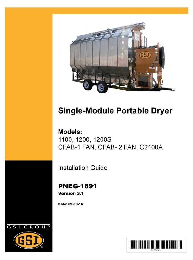
1 and 2 Fan Vision Series
Portable Dryers
Operator’s Manual
PNEG-1456
Date: 08-02-10

2 PNEG-1456 1 and 2 Fan Vision Series Portable Dryers

Table of Contents
PNEG-1456 1 and 2 Fan Vision Series Portable Dryers 3
Contents
Chapter 1 Safety .....................................................................................................................................................4
Safety Guidelines .................................................................................................................................. 4
Dryer Operation ..................................................................................................................................... 5
Emergency Stop Switch ........................................................................................................................ 5
Safety Precautions ................................................................................................................................ 6
Chapter 2 Decals ....................................................................................................................................................8
Chapter 3 Specifications .....................................................................................................................................12
Dryer Dimensions ................................................................................................................................ 12
Chapter 4 Test Firing ...........................................................................................................................................16
Dryer Pre-Season Checks .................................................................................................................. 16
Inspect the Metering Rolls ................................................................................................................... 16
Check Control Panel Switches ............................................................................................................ 16
Electrical Power .................................................................................................................................. 16
Control Power Switch .......................................................................................................................... 16
Start Switch ......................................................................................................................................... 16
Fuel Check .......................................................................................................................................... 16
Load Auger .......................................................................................................................................... 17
Unload Auto Operation ........................................................................................................................ 17
Unload Manual Operation ................................................................................................................... 17
Meter Roll Operation ........................................................................................................................... 17
Fan Switches ....................................................................................................................................... 17
Burner Safety ...................................................................................................................................... 18
Burner Test Fire .................................................................................................................................. 18
Dryer Shutdown .................................................................................................................................. 20
Emergency .......................................................................................................................................... 20
Chapter 5 Dryer Operation ..................................................................................................................................21
Dryer Start-Up and Operation Full Heat Drying .................................................................................. 21
Drying Temperatures .......................................................................................................................... 21
Dryer Shutdown .................................................................................................................................. 21
Initial Setup Parameters ...................................................................................................................... 21
Timer and Delay Setting ...................................................................................................................... 22
Setting the Temperatures .................................................................................................................... 22
Start-Up ............................................................................................................................................... 22
Continuous Flow Drying Mode Using Regulation of Grain Temperature ............................................ 23
Continuous Flow Drying Mode Using Regulation of Moisture: 5 MR SP ............................................ 30
Chapter 6 Illustrations .........................................................................................................................................34
Chapter 7 Service .................................................................................................................................................42
Seasonal Inspection and Service ........................................................................................................ 42
Lubrication Procedure ......................................................................................................................... 43
Fan Blade Removal and Installation ................................................................................................... 44
Fan Motor Removal ............................................................................................................................. 44
Heater Parts Removal and Installation ................................................................................................ 45
Metering Roll Servicing ....................................................................................................................... 46
Main Controls ...................................................................................................................................... 46
How to Clear a Jammed Metering Roll ............................................................................................... 46
Chapter 8 Warranty ..............................................................................................................................................47
4 PNEG-1456 1 and 2 Fan Vision Series Portable Dryers
1. Safety
Safety Guidelines
This manual contains information that is important for you, the owner/operator, to know and understand.
This information relates to protecting personal safety and preventing equipment problems. It is the
responsibility of the owner/operator to inform anyone operating or working in the area of this equipment
of these safety guidelines. To help you recognize this information, we use the symbols that are defined
below. Please read the manual and pay attention to these sections. Failure to read this manual and its
safety instructions is a misuse of the equipment and may lead to serious injury or death.
This is the safety alert symbol. It is used to alert you to
potential personal injury hazards. Obey all safety
messages that follow this symbol to avoid possible
injury or death.
WARNING indicates a potentially hazardous situation
which, if not avoided, could result in death or serious injury.
CAUTION indicates a potentially hazardous situation which,
if not avoided, may result in minor or moderate injury.
CAUTION used without the safety alert symbol indicates a
potentially hazardous situation which, if not avoided, may
result in property damage.
NOTE indicates information about the equipment that you
should pay special attention.
DANGER indicates an imminently hazardous situation
which, if not avoided, will result in death or serious injury.
Personnel operating or working around electric fans should read this manual. This
manual must be delivered with the equipment to its owner. Failure to read this manual
and its safety instructions is a misuse of the equipment.
WARNING! BE ALERT!

1. Safety
PNEG-1456 1 and 2 Fan Vision Series Portable Dryers 5
Dryer Operation
Thank you for choosing a GSI product. It is designed to give excellent performance and service for
many years.
This manual describes the operation and service for all standard production model dryers. These models
are available for liquid propane or natural gas fuel supply, with either 1 phase 230 volt, or 3 phase
230 or 440 volt electrical power.
Our foremost concern is your safety and the safety of others associated with this equipment. We want to
keep you as a customer. This manual is to help you understand safe operating procedures and some
problems which may be encountered by the operator and other personnel.
As owner and/or operator, it is your responsibility to know what requirements, hazards and precautions
exist, and to inform all personnel associated with the equipment or in the area. Safety precautions may be
required from the personnel. Avoid any alterations to the equipment. Such alterations may produce a very
dangerous situation where SERIOUS INJURY or DEATH may occur.
This equipment shall be installed in accordance with the current installation codes and applicable
regulations which should be carefully followed in all cases. Authorities having jurisdiction should be
consulted before installations are made.
Emergency Stop Switch
The Emergency Stop switch is located on the upper control box door. Pushing the Emergency
Stop switch will interrupt the control power and stop all dryer functions.
Pushing the Emergency Stop switch does not interrupt the main power to the
upper control box panel.

1. Safety
6 PNEG-1456 1 and 2 Fan Vision Series Portable Dryers
Safety Precautions
READ THESE INSTRUCTIONS BEFORE INSTALLATION AND OPERATION
SAVE FOR FUTURE REFERENCE
1. Read and understand the operating manual before attempting to operate the dryer.
2. NEVER operate the dryer while the guards are removed.
3. PowersupplyshouldbeOFFforserviceofelectricalcomponents.UseCAUTION incheckingvoltage
or other procedures requiring the power to be ON.
4. Check for gas leaks at all gas pipe connections. If any leaks are detected,
DO NOT
operate dryer.
Shutdown and repair before further operation.
5. NEVER attempt to operate the dryer by jumping or otherwise bypassing any safety devices on
the unit.
6. Set pressure regulator to avoid excessive gas pressure being applied to the burner during ignition
and when the burner is in operation. See Chart on Page 18 for operating procedures. DO NOT
exceed maximum recommended drying temperature.
7. Keep the dryer clean. DO NOT allow fine material to accumulate in the plenum chamber.
Clean grain is easier to dry. Fine material increases resistance to airflow and requires removal
of extra moisture.
8. Keep auger drive belts tight enough to prevent slippage.
9. Use CAUTION in working around high speed fans, gas burners, augers and auxiliary conveyors
which can START AUTOMATICALLY.
10. Keep area around air inlet to the fan clear of any obstacles and combustible materials.
11. BEFORE attempting to remove and reinstall any propeller, make sure to read the recommended
procedure listed in the Service Section on Page 42 of the manual.
12. Make sure that capacities of auxiliary conveyors are matched to dryer auger capacities.
13. DO NOT operate in an area where combustible material will be drawn into the fan.
14. The operating and safety recommendations in this manual pertain to the common cereal
grains as indicated. When drying any other grain or products, consult the factory for
additional recommendations.
15. Routinely check for any developing gas plumbing leaks. Check LP vaporizer for contact with
burner vanes.

1. Safety
PNEG-1456 1 and 2 Fan Vision Series Portable Dryers 7
Use Caution in the Operation of this Equipment
This dryer is designed and manufactured with operator safety in mind. However, the very nature of a grain
dryer having a gas burner, high voltage electrical equipment and high speed rotating parts, presents
hazardstopersonnelwhichcannot becompletely safeguardedagainstwithoutinterfering withthe efficient
operation of the dryer and reasonable access to its components.
Use extreme caution in working around high speed fans, gas-fired heaters, augers and auxiliary
conveyors, which may start without warning when the dryer is operating on automatic control.
Continued safe, dependable operation of automatic equipment depends, to a great degree, upon the owner.
For a safe and dependable drying system, follow the recommendations within the Owner’s Manual and make
it a practice to regularly inspect the unit for any developing problems or unsafe conditions.
Take special note of the Safety Precautions on Page 6 before attempting to operate the dryer.

8 PNEG-1456 1 and 2 Fan Vision Series Portable Dryers
2. Decals
The GSI Group recommends contacting the local power company and having a representative survey the
installation so the wiring is compatible with their system and adequate power is supplied to the unit. Safety
decals should be read and understood by all people in the grain handling area.
If a decal is damaged or is missing, contact:
GSI Decals
1004 E. Illinois St.
Assumption, IL. 62510
Phone: 1-217-226-4421
A free replacement will be sent to you.
Decal: DC-889
Decal DC-889 has two (2) locations. One inside
the fan/heater control box and another on the
dryer upper control box door next to the main
power disconnect.
Decal: DC-1224
Decal DC-1224 is located in two (2) places on the fan/heater control box.
One on the lid and one on the front of the fan heater control box.
Another location for this decal is inside the upper control box for the dryer.

2. Decals
PNEG-1456 1 and 2 Fan Vision Series Portable Dryers 9
Moving parts can crush
and cut. Keep hands
clear. Do not operate
without guards in place.
Failure to do so could
result in serious injury.
DC-972
WARNING!
DC-974
Rotating auger will crush
and cut. Auto equipment
can start at anytime. Do not
enter until electric power is
locked in off position. Failure
to do so will result in serious
injury or death.
WARNING!
Automatically controlled
belt drive can start at
anytime. Keep hands
clear. Failure to do so
could result in serious
injury.
DC-971
Decal: DC-972
Decal DC-972 is located on the bottom auger belt guard and the front bearing
plate (which is visible when the bottom auger belt guard is removed).
An alternate location would be at the rear of the dryer for portable dryers
equipped with the Front Discharge Option.
Decal: DC-971
Decal DC-971 is located on the bottom auger belt guard and the front bearing plate
(which is visible when the bottom auger belt guard is removed). An alternate location
would be at the rear of the dryer for portable dryers equipped with the
Front
Discharge Option
.
Another location for decal DC-971 is on the top of the auger belt guard (one on the
belt guard cover and one on the inside belt guard body visible when the belt guard
cover is removed).
Decal: DC-974
Decal DC-974 has several different locations. Two (2) are located on the front end
panel below the fan/heater. Two (2) are located on the rear end panel below the rear
access door. Two (2) are located on the auger discharge box (one on the outside top
and one on the inside of the flapper lid next to the discharge mercury switch). One
more of these decals is located inside the plenum on the rear plenum closure door
just inside the rear access door.

2. Decals
10 PNEG-1456 1 and 2 Fan Vision Series Portable Dryers
DC-1229
WARNING
Rotating metering roll.
Equipment can start
automatically. Keep hands
clear. Can cause serious
injury. Disconnect power
before servicing.
Decal: DC-1229
Decal DC-1229 is located on each of
the meter roll access doors.
Automatic equipment can
start at anytime. Do not
enter until fuel is shut off
and electrical power is
locked in off position.
Failure to do so will result
in serious injury or death.
DC-973
Decal: DC-973
Decal DC-973 is located on the rear plenum access door (inside
and outside).
DC-1227
Flame and pressure beyond
door can cause serious
injury. Do not operate with
service door removed. Keep
head and hands clear.
WARNING
Decal: DC-1227
Decal DC-1227 is located on the
fan/heater access door.

2. Decals
PNEG-1456 1 and 2 Fan Vision Series Portable Dryers 11
DC-1249
Dryer must be
towed empty and
in accordance
with state and
provincial
regulations.
HUB TEMPERATURE
TIGHTEN TO
90FT-LBS.
55-60 PSI
COLD
CHECK AFTER 50 MILES AND EVERY 200 MILES
050
100 150 200 250
NO GREATER THAN 150°F
150°
16-17"
3/4" MINIMUM
BOLT DIAMETER
DC-388
Hitch pin must be
securely fastened and
no less than 3/4" in
diameter. Failure to
follow installation
instructions may result
in property damage.
Decal: DC-388
Decal DC-388 is located on the
hitch tongue.
Decal: DC-1249
Decal DC-1249 is located on the
hitch tongue.
Stay clear of rotating
blade. Blade could start
automatically. Can cause
serious injury. Disconnect
power before servicing.
DC-1225
WARNING
Decal: DC-1225
Decal DC-1225 is located on the
fan/heater access door.

12 PNEG-1456 1 and 2 Fan Vision Series Portable Dryers
3. Specifications
Dryer Dimensions
Figure 3A
Figure 3B

3. Specifications
PNEG-1456 1 and 2 Fan Vision Series Portable Dryers 13
Single Module Transport and Installation Dimensions
Values are Valid for Transportation of Stack Modules
Dryer
Basket
AB C DEFGH
Transport
Height Installed
Width
Installed Height Height w/o
Wet Bin Frame
Width Transport
Width Installed
Length Transport
Length
Wet Bin Standard Top
1108T 13' 5'' 8' 14' 6'' 13' 11' 9'' 6' 5'' 8' 15' 2'' 17' 2''
1112 13' 5'' 8' 14' 6'' 13' 11' 9'' 6' 5'' 8' 19' 2'' 21' 2''
1114 13' 5'' 8' 14' 6'' 13' 11' 9'' 6' 5'' 8' 21' 2'' 23' 2''
1116 13' 5'' 8' 14' 6'' 13' 11' 9'' 6' 5'' 8' 23' 2'' 25' 2''
1118 13' 5'' 8' 14' 6'' 13' 11' 9'' 6' 5'' 8' 25' 2'' 27' 2''
1120 13' 5'' 8' 14' 6'' 13' 11' 9'' 6' 5'' 8' 27' 2'' 29' 2''
1122 13' 5'' 8' 14' 6'' 13' 11' 9'' 6' 5'' 8' 29' 2'' 31' 2''
1126 13' 5'' 8' 14' 6'' 13' 11' 9'' 6' 5'' 8' 33' 2'' 35' 2''
1214 13' 5'' 8' 14' 6'' 13' 11' 9'' 6' 5'' 8' 21' 2'' 23' 2''
1216 13' 5'' 8' 14' 6'' 13' 11' 9'' 6' 5'' 8' 23' 2'' 25' 2''
1218 13' 5'' 8' 14' 6'' 13' 11' 9'' 6' 5'' 8' 25' 2'' 27' 2''
1220 13' 5'' 8' 14' 6'' 13' 11' 9'' 6' 5'' 8' 27' 2'' 29' 2''
1222 13' 5'' 8' 14' 6'' 13' 11' 9'' 6' 5'' 8' 29' 2'' 31' 2''
1226 13' 5'' 8' 14' 6'' 13' 11' 9'' 6' 5'' 8' 33' 2'' 35' 2''
1214S 13' 5'' 8' 8'' 14' 6'' 13' 11' 9'' 6' 5'' 8' 21' 2'' 23' 2''
1218S 13' 5'' 8' 8'' 14' 6'' 13' 11' 9'' 6' 5'' 8' 25' 2'' 27' 2''
1220S 13' 5'' 8' 8'' 14' 6'' 13' 11' 9'' 6' 5'' 8' 27' 2'' 29' 2''
1222S 13' 5'' 8' 8'' 14' 6'' 13' 11' 9'' 6' 5'' 8' 29' 2'' 31' 2''
1226S 13' 5'' 8' 8'' 14' 6'' 13' 11' 9'' 6' 5'' 8' 33' 2'' 35' 2''

3. Specifications
14 PNEG-1456 1 and 2 Fan Vision Series Portable Dryers
Figure 3C
1100 Series Dryer Specifications
1108T 1112 1114 1116 1118 1120 1122 1126
Total Holding Capacity (Bushels) 190 327 381 436 490 544 599 708
Grain Column Holding Capacity (Bushels) 160 282 329 376 423 470 517 611
Fan 28''
10-13 HP 36''
15 HP 40''
15 HP 40''
15 HP 42''
20 HP 42''
25 HP 42''
30 HP 42''
40 HP
Top Auger 8'' Dia.
1-1/2 HP 8'' Dia.
3 HP 8'' Dia.
5 HP 8'' Dia.
5 HP 8'' Dia.
5 HP 8'' Dia.
7-1/2 HP 8'' Dia.
7-1/2 HP 8'' Dia.
10 HP
Capacity (BHP) 2900 2900 3800 3800 3800 3800 3800 3800
Bottom Auger 8'' Dia.
1 HP 8'' Dia.
1-1/2 HP 8'' Dia.
3 HP 8'' Dia.
5 HP 8'' Dia.
5 HP 8'' Dia.
7-1/2 HP 8'' Dia.
7-1/2 HP 8'' Dia.
10 HP
Meter Roll Drive SCR,
1/3 HP SCR,
1/3 HP SCR,
3/4 HP SCR,
3/4 HP SCR,
3/4 HP SCR,
3/4 HP SCR,
3/4 HP SCR,
3/4 HP
Capacity - MAXIMUM Rate1(BHP) 1120 1680 1960 2240 2520 2800 3080 3640
Electrical Load (Fans, Top and Bottom Augers2)
1 Phase, 220 Volt 63 85 98 108 - - - -
3 Phase, 220 Volt 42 50 56 65 80 104 114 150
3 Phase, 440 Volt 21 25 28 33 40 52 57 75
3 Phase, 575 Volt 18 20 23 27 32 42 46 61
3 Phase, 380 Volt 22 33 36 44 49 68 75 88
1. Actual discharge rate is controlled by meter roll speed adjustment, at 5% to 100% of maximum rate.
2. Excludes auxiliary load and unload conveyor equipment.
1100 Series profile 1200 Series profile 1200S Series profile

3. Specifications
PNEG-1456 1 and 2 Fan Vision Series Portable Dryers 15
1200 Series Dryer Specifications
1200S Series Dryer Specifications
1214 1216 1218 1220 1222 1226
Total Holding Capacity (Bushels) 381 436 490 544 599 708
Grain Column Holding
Capacity (Bushels) 329 376 423 470 517 611
Fan 26'' 10-13 HP
36'' 10-13 HP 26'' 10-13 HP
36'' 15 HP 26'' 10-13 HP
36'' 15 HP 28'' 10-13 HP
40" 15 HP 28'' 10-13 HP
42'' 20 HP 28'' 10-13 HP
42'' 25 HP
Top Auger 8'' Dia.
5 HP 8'' Dia.
5 HP 8'' Dia.
5 HP 8'' Dia.
7-1/2 HP 8'' Dia.
7-1/2 HP 8'' Dia.
10 HP
Capacity (BHP) 3800 3800 3800 3800 3800 3800
Bottom Auger 8'' Dia.
5 HP 8'' Dia.
5 HP 8'' Dia.
5 HP 8'' Dia.
7-1/2 HP 8'' Dia.
7-1/2 HP 8'' Dia.
10 HP
Meter Roll Drive SCR, 3/4 HP SCR, 3/4 HP SCR, 3/4 HP SCR, 3/4 HP SCR, 3/4 HP SCR, 3/4 HP
Capacity - MAXIMUM Rate1BHP) 1960 2240 2520 2800 3080 3640
Electrical Load (Fans, Top and Bottom Augers2)
1 Phase, 220 Volt 142 156 156 172 - -
3 Phase, 220 Volt 92 99 99 112 126 150
3 Phase, 440 Volt 47 50 50 57 63 75
3 Phase, 575 Volt 37 42 42 47 52 61
3 Phase, 380 Volt 50 61 61 70 75 90
1. Actual discharge rate is controlled by meter roll speed adjustment, at 5% to 100% of maximum rate.
2. Excludes auxiliary load and unload conveyor equipment.
1214S 1218S 1220S 1222S 1226S
Total Holding Capacity (Bushels) 381 490 544 599 708
Grain Column Holding Capacity (Bushels) 329 423 470 517 611
Fan 28'' 10-13 HP
(2) 36'' 10-13 HP
(2) 36'' 15 HP
(2) 36'' 15 HP
(2) 40'' 25 HP
(2)
Top Auger 8'' Dia.
5 HP 8'' Dia.
5 HP 8'' Dia.
7-1/2 HP 8'' Dia.
7-1/2 HP 8'' Dia.
10 HP
Capacity (BHP) 3800 3800 3800 3800 3800
Bottom Auger 8'' Dia.
5 HP 8'' Dia.
5 HP 8'' Dia.
7-1/2 HP 8'' Dia.
7-1/2 HP 8'' Dia.
10 HP
Meter Roll Drive SCR, 3/4 HP SCR, 3/4 HP SCR, 3/4 HP SCR, 3/4 HP SCR, 3/4 HP
Capacity - MAXIMUM Rate1(BHP) 1960 2520 2800 3080 3640
Electrical Load (Fans, Top and Bottom Augers2)
1 Phase, 220 Volt 142 142 186 186 -
3 Phase, 220 Volt 93 93 118 118 180
3 Phase, 440 Volt 47 47 60 60 90
3 Phase, 575 Volt 40 33 48 48 72
3 Phase, 380 Volt 50 50 80 80 115
1. Actual discharge rate is controlled by meter roll speed adjustment, at 5% to 100% of maximum rate.
2. Excludes auxiliary load and unload conveyor equipment.

16 PNEG-1456 1 and 2 Fan Vision Series Portable Dryers
4. Test Firing
Dryer Pre-Season Checks
Before staring the drying for the first time in a drying season, perform the following checks. If any of the
checks fail to produce the stated result, the customer should consult your dealer.
Do not attempt to use the dryer unless all the pre-start checks have been successfully completed.
Inspect the Metering Rolls
Open all metering roll access doors and inspect each compartment for any bolts, nuts or other foreign
material that may cause possible jamming of the metering rolls.
Check Control Panel Switches
Before applying electrical power to the dryer, be sure that all switches on the dryer control panel are in the
OFF position.
Electrical Power
Turn ON the electrical power supply to the dryer, set all circuit breakers to ON, including the safety
disconnect handle mounted on front of the dryer power panel.
Control Power Switch
TurntheControlPower switch toON. At thispoint,the controllerwilllock outallother dryer functions.Once
the Boot Screen appears, touch the Start button and the dryer will perform a safety circuit check. If a fault
is found, the cause will be displayed on the main screen. If all circuits are safe, the controller will supply
power to the electronic fuel shut off valve (Maxon), if so equipped and the Start switch will illuminate,
indicating that the dryer is ready to be started.
Start Switch
Push the Start switch and all the selector switches on the control panel will be activated.
Fuel Check
If using LP gas, makesure the tankhas plenty offuel and that thetank does not havea regulator mounted
on the liquid line. Slowly open the main fuel supply valve at the tank. Then, open the electronic shut off
valve (Maxon valve), if so equipped, or open the manual shut off valve on the dryer to allow fuel flow to
the dryer.
If using natural gas, make sure an adequate supply is available. Turn ON the valve along the supply line. Then,
open the electronic shut off valve (Maxon valve). Inspect all gas lines and connections for possible leaks.
Before attempting to operate the dryer, make sure all safety shields are in place,
all bottoms are cleaned out and rear access doors are closed and all personnel
are clear of the dryer.
Any gas leaks must be fixed immediately.

4. Test Firing
PNEG-1456 1 and 2 Fan Vision Series Portable Dryers 17
Load Auger
With the grain supply shut off, quickly flip the Load Auger switch to MANUAL and see if the load auger
rotates clockwise as viewed from the drive end, or counterclockwise if the dryer is a front loadmodel. If the
wet grain supply auxiliary is wired to the dryer, it should also rotate in the correct direction at this time.
Turn the Load Auger switch to the AUTO position. The top auger and wet grain supply auxiliary should
run for 8 minutes and then the dryer will shutdown and the safety shutdown message (out of grain
warning) will be displayed. Press the Stop button to reset the panel, then press the Start button.
Unload Auto Operation
To check Auto operation, place the Unload switch in the AUTO position. Push then turn the meter roll
dial to a setting of 500 andtouch ACCEPT/EXIT to start the meter roll rotation. The bottomauger should
rotate counterclockwise as viewed from the driveend. The meter roll drive motor should rotate clockwise
as viewed from the drive end of the gear box. If the dry grain take away auxiliary is wired to the dryer, it
should start and rotate in the proper direction.
Unload Manual Operation
To check Manual operation, move the Unload switch in the MANUAL position. Push then turn the meter
roll dial to a setting of 500 and touch ACCEPT/EXIT to start the meter roll rotation. The bottom auger
should rotate counterclockwise as viewed from the drive end. The meter roll drive motor should rotate
clockwise as viewed from the drive end of the gear box. If the dry grain take away auxiliary is wired to
the dryer, it should start and rotate in the proper direction.
Meter Roll Operation
When the meter rolls are set to maximum (1000), the meter roll speed should be 17.5 RPM for 8'' (20 cm)
discharge augers. Make sure the drive chain tension is properly adjusted and all sections of the meter rolls
rotate. Turn the Unload switch OFF after these checksare complete. The bottom auger will continue to run
for 60 seconds (the default clean out delay setting) after the switch is turned OFF to allow for clean out.
NOTE: Due to the nature of the DC drive motor used on the meter rolls, it is possible for the brushes
inside the motor to become corroded if the dryer has not been operated for several months. This
will cause the meter rolls not to function. To fix this problem, use a rubber mallet or a piece of
wood to tap the DC drive motor. The shock is usually sufficient to restart the motor and metering
rolls. You should not have any more problems with this during the rest of the drying season.
Fan Switches
Briefly turn each Fan switch to ON and observe the fan rotation. The fan should run counterclockwise.
Sometimes,on3phasemodels, allmotorsrunbackwards.Theycaneasilybe reversedbyinterchanging
two of the three power supply wires. Reverse the two (2) outside wires, L1 and L3 and leave the middle
one in the same position.
NOTE: The bottom fan on the dryer is always referred to as fan 1.
All power should be switched OFF and locked out before attempting to reverse
the connections.

4. Test Firing
18 PNEG-1456 1 and 2 Fan Vision Series Portable Dryers
Burner Safety
To check the burner safety function, first make sure the main gas valve is OFF. Turn the Fan switch ON and
allow the fan to start. Turn the Heater switch ON for that fan. The dryer will shutdown after 20 seconds. The
safety message, “Ignition Failure Fan #” will appear. Reset the dryer and repeat for the other fan/heater(s).
Burner Test Fire
To perform this test, the dryer must be full of grain. If the dryer is empty, the air switch must be disabled.
To disable, touch the Setup button at the bottom of theDefault Operation Screen. When the Setup Screen
appears, touch the Diagnostics button to display the System Diagnostics. To disable the air switch, select
the Disable Testing button in the air switch box of the System Diagnostics Screen. The Vision computer
will then display a prompt asking if you wish to disable the air switch. Choose YES to continue. Once the
air switches are disabled, the Fan switches on the switch panel will illuminate and the fan/heaters on the
display animation will change to blue, indicating that “airflow” is simulated.
There is only a 5 minutes period after the dryer is turned on that the air switches can be disabled. After
5 minutes, the air switches cannot be disabled and any air switches that are disabled will return to the
enabled state causing an airflow shutdown if the dryer is empty. To restart the 5 minutes test period, the
dryer must be shutdown and restarted. The 5 minutes test period starts when the Control Power switch is
turned ON.
Test fire each burner by starting the fan. Turn on the fuel supply, then turn the Burner switch to ON. The
burner should ignite after a short purge delay of approximately 10 seconds. Gas pressure should be shown
on the gauge. At this time adjust the plenum setpoint to 200°F (93°C), causing the burner to operate on
High-Fire. Observe the gas pressure on the gauge andlower the plenum setpoint until it causes the burner
to cycle into Low-Fire. When the plenum temperature setpoint is met, the gas pressure should show a
noticeable drop, indicating that the cycle solenoid is closed and the burner is being supplied with less gas
through the cycle solenoid bypass port. At this time set the High-Fire and Low-Fire pressure settings. Use
the pressure regulator (for LP models) or the supply line ball valve (for natural gas models) for High-Fire
and the adjustment screw on the cycle solenoid for Low-Fire. The computer should cycle the burners
between high and low, approximately 1 to 3 times per minute.
Use only the amount of pressure required to obtain the desired temperature.
Approximate settings are shown below:
If the burner remains on High-Fire and does not cycle, increase the regulator setting on the propane
models, or the supply valve on the natural gas models, in order to reach the plenum setpoint. If the burner
remains in Low-Fire and does not cycle, slightly decrease gas pressure with the Low-Fire adjustment
screw on the cycle solenoid. If the gas pressure is decreased too much, a popping or fluttering sound will
be heard. This popping and fluttering should not be allowed to continue or damage to the burner will occur.
Be sure to adjust the low pressure needle valve anytime the high pressure regulator is adjusted. Repeat
the test for each fan/heater unit.
LP Gas Natural Gas
High-Fire 6-15 PSI (41-102 kPa) High-Fire 6-10 PSI (41-69 kPa)
Low-Fire 2-6 PSI (14-41 kPa) Low-Fire 1-3 PSI (7-20 kPa)

4. Test Firing
PNEG-1456 1 and 2 Fan Vision Series Portable Dryers 19
Figure 4A Liquid Propane (LP) Pipe Train
Figure 4B Natural Gas (NG) Pipe Train
Low-fire needle valve
Pressure regulator
(high-fire)
Watchgauge
for pressure
Supply line ball
valve (high-fire)
Low-fire needle
valve
Watchgauge
for pressure

4. Test Firing
20 PNEG-1456 1 and 2 Fan Vision Series Portable Dryers
Dryer Shutdown
To shutdown the dryer:
1. Close the fuel supply valve at the tank or valve along the fuel line.
2. If the burner is operating, let the dryer run out of fuel and it will shutdown automatically due to loss
of flame.
3. Close the fuel valve at the dryer and press the Stop button.
4. Turn OFF the control power.
5. Turn OFF the safety disconnect handle on the front of the power box and turn OFF the main power
to the dryer.
Emergency
In case of emergency, push the Emergency Stop button. This will interrupt power to the control panel and
the fan; burner and all augers will stop immediately.
Other manuals for 1100
2
This manual suits for next models
21
Table of contents
Other GSi Dryer manuals

GSi
GSi Q112 User manual

GSi
GSi TopDry Autoflow 24 Ft Instructions for use

GSi
GSi PNEG-902 User manual

GSi
GSi PNEG-2132 User manual

GSi
GSi CSA - Mod/T User manual

GSi
GSi TopDry Autoflow 2000 Series User manual

GSi
GSi PNEG-902 User manual

GSi
GSi 1100 User manual

GSi
GSi 2314 User manual

GSi
GSi TM-Series User manual