manuals.online logo
Brands
  1. Home
  2. •
  3. Brands
  4. •
  5. GSL electronics
  6. •
  7. Batteries Charger
  8. •
  9. GSL electronics REC25HV User manual

GSL electronics REC25HV User manual

Page 1 of 4
Model:
REC25HV
Unit 2, 110 Station Road, Seven Hills ,NSW, 2147, Australia
25A High Voltage Reducer / Charger
Operating Instructions
Please read these instructions before use
Congratulations on purchasing your new GSL Electronics High Voltage Reducer/Charger. This product utilises
Switchmode and Microprocessor technology for the charging of 12V and 24V Batteries(Lithium,AGM,GEL and
Flooded Cell). As well as charging functionality it is also able to act as a standard Reducer from inputs as high
as 80V to either 12V or 24V. The charger provides a safe and fast method of restoring discharged batteries
and maintaining them. This is achieved via precisely controlled Bulk, Absorption and Float charging states. It is
fully protected against overload, short circuit, over temperature, over voltage and with a bulk charge timeout for
additional safety. The models are built in a compact and strong aluminium extrusion which can be easily secured
to both vertical and horizontal surfaces. Before starting the charge cycle the battery voltages are evaluated to
detect faulty batteries.
Bulk Mode – This mode of the battery charger delivers bulk charging current regulated to 25 Amps into the
battery being charged. After the battery voltage rises to approximately 70% charge. The charger will switch
automatically into Absorption Mode.
Absorption Mode – In this mode the battery charger output voltage is maintained at 14.5V / 29V until the current
drops below a controlled threshold. The battery is brought up to a 90% charge then enters oat mode.
Float Mode - The voltage is reduced to 13.5V / 27V and maintained at that level with the charger supplying just
enough current to maintain the battery at full capacity.
Fixed Mode(Reducer Mode Only) : When the unit is set to REDUCER mode the unit will output a xed voltage
of either 13.5V or 27V.
REC-HV-R2
Installation & Safety Precautions:
1. Before mounting ensure that you have set the internal jumpers to suit your batteries and your system. Refer to
Page 3 for how to access and set the jumpers.
2. The following connection sequence is to be followed after the Batteries have been disconncted and isolated
from the installation:
Ground (BLACK), Input (WHITE), Output (RED) and Control (BLUE).
3. Preferably mount the unit inside the vehicle. Avoid locations where external heat is produced e.g. exhaust
system or where the batteries are located.
4. Choose a position with good ventilation where air can pass freely around the unit.
5. Ensure the unit is protected from water spray and other sources of contamination e.g. oil, grease and dust.
6. Ensure that unit is installed away from any ammable fumes, liquids or materials.
7. During charging process, do not use a naked ame near a battery, due to gases emitted from the battery,
which may ignite and explode.
More information https://www.caravansplus.com.au
LED Indicators:
Your new charger is tted with a microprocessor which evaluates the state of the charge and displays the
operating mode of the unit via two LED indicators.
Input LED:
Nominal operation is indicated by the Input LED remaining solid.
Flashing Input LED indicates that input is below 23V/46V. If the input voltage drops below 22V/44V charger will
switch off. When the voltage returns to above 23V/46V the unit will return to normal operation.
Output LED:
This LED indicates the charge state of the battery charger
When the LED is ashing this indicates that the charger is in a charge state.
A solid output LED indicates a charged battery and that the charger is in oat mode.
The LED will remain off when either:-
A) The charger’s battery sensing technology does not sense a battery on the output.
B) The Ignition Wire is disconnected.
C) Output Over Voltage or Thermal Protection
Page 2 of 4
Model:
REC25HV
Unit 2, 110 Station Road, Seven Hills ,NSW, 2147, Australia
25A High Voltage Reducer / Charger
Operating Instructions
Please read these instructions before use
7. Never smoke or light cigarettes near a battery.
8.Do not place tools on top of battery or allow tools to fall on battery.
9. Always wear eye protection near a charging battery.
10. Ensure a “well” ventilated area is used when testing or re-charging batteries.
11. Ensure ventilation is adequate and venting holes are not obstructed. Inadequate ventilation may over-heat the
unit and cause inefcient operation.
12. If skin or clothing comes into contact with acid, ush the area(s) with water immediately.
Seek medical attention if necessary.
REC-HV-R2
If the unit is in the following conditions. reset as follows:
- Output Over Voltage: If the output over voltage protection has been tripped then there will be no operation from
the unit. Contact supplier or GSL Electronics for Warranty Advice.
- Thermal Protection: For your safety and for the longevity of your purchase, the unit will shut down to protect itself
and your batteries when the unit exceeds it nominal operating temperature. To reset this condition the unit must be
disconnected from the battery for at least one minute to allow cooling and for the microprocessor to reset.
Should product require service, return it to your place of purchase for Warranty Advice.
More information https://www.caravansplus.com.au
Page 3 of 4
Model:
REC25HV
Unit 2, 110 Station Road, Seven Hills ,NSW, 2147, Australia
25A High Voltage Reducer / Charger
Operating Instructions
Please read these instructions before use
REC-HV-R2
Setting the Jumpers:
Remove the vented back plate from the unit by unscrewing the 7 screws as pictured above.
Slide out the bottom plate and set aside.
Locate the desired jumper to be changed in the above image.
Reassemble in reverse order to above after changing the desired jumper settings.
The positions are as follows:
J10 - No Link - (Factory Default) AGM / GEL. Absorption 14.3V/28.6V , Float 13.5V/27V
Link 1&2 - Lithium. Absorption 14.6V/29.2V , Float 12.6V/25.2V
Link 2&3 - Vented Lead Acid. Absorption 14.5V/29V, Float 13.5V/27V
B6 - Linked - 12V Mode (Factory Default)
No Link - 24V Mode
A2 - Linked - Charger mode (Chemistry set by J10)
No Link - Reducer Mode, Fixed output 13.5V/27V (Voltage set by B6)
IGN - Link 1&2 - Constant ON - Where the igition wire is not used and alternative arangments
are made to turn the unit on and off via input. With no battery to charge or no
load Constant ON will draw <70mA.
Link 2&3 - Ignition Controlled - A Positive feed to the ignition wire of the unit is required
to activate unit. No current drain(less than 1mA) whilst the ignition is off.
Unlinked - Unit OFF - Unit will remain off no matter the condition of the ignition wire or
input to the unit.
More information https://www.caravansplus.com.au
Page 4 of 4
Model:
REC25HV
Unit 2, 110 Station Road, Seven Hills ,NSW, 2147, Australia
25A High Voltage Reducer / Charger
Operating Instructions
Please read these instructions before use
Warranty Conditions: The product is warranted to be free from defects in materials and workmanship under normal use and service for a period
of 24 months from the date of sale. This warranty covers defective parts and workmanship provided that the product is shipped prepaid to the
seller within 24 months of purchase of goods. This warranty is limited to the repair or replacement (at the manufacturers’ discretion) of parts
and shipping prepaid to the original despatch destination. We regret that no liability can be accepted for consequential or special damages
of any kind howsoever arising in connection with products supplied by the seller. This warranty is in lieu of all other warranties expressed or
implied. No representative is authorised to assume for the seller any other liability in connection with the seller’s products.
REC-HV-R2
Specications REC25HV
Input Voltage Range [ VDC ]
12V Mode Shutdown : 18V ± 5% Turn On : 22V ± 5%
24V Mode Shutdown : 36V ± 5% Turn On : 44V ± 5%
Typical Efciency Greater than 85%
Bulk Charge Current [A] 25A
Stand – By Current [mADC] <70mA Ingition On , <1mA Ignition Off
Features Short Circuit Protection
Over Voltage and Thermal Protection
Dimensions [ L x W x H] 155mm x 177mm x 68mm
Weight 1.4Kg
More information https://www.caravansplus.com.au
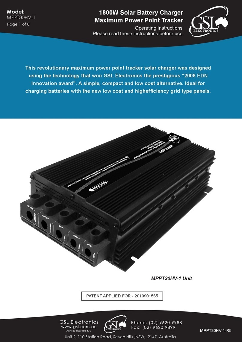
Other GSL electronics Batteries Charger manuals

GSL electronics BC240-1230-S User manual

GSL electronics

GSL electronics BC240-1230-S User manual

GSL electronics MPPT10HV User manual

GSL electronics

GSL electronics MPPT10HV User manual

GSL electronics BMPPT800 User manual

GSL electronics

GSL electronics BMPPT800 User manual

GSL electronics BMPPT250 User manual

GSL electronics

GSL electronics BMPPT250 User manual

GSL electronics VDBC1224-20-NG-2 User manual

GSL electronics

GSL electronics VDBC1224-20-NG-2 User manual

GSL electronics MPPT60-2 User manual

GSL electronics

GSL electronics MPPT60-2 User manual

GSL electronics MPPT60-1HV User manual

GSL electronics

GSL electronics MPPT60-1HV User manual

GSL electronics MCB-1225 User manual

GSL electronics

GSL electronics MCB-1225 User manual

GSL electronics MPPT30-1L User manual

GSL electronics

GSL electronics MPPT30-1L User manual

GSL electronics MPPT30HV-1 User manual

GSL electronics

GSL electronics MPPT30HV-1 User manual

GSL electronics MPPT12-2P User manual

GSL electronics

GSL electronics MPPT12-2P User manual

GSL electronics DIBC1224-1230 User manual

GSL electronics

GSL electronics DIBC1224-1230 User manual

GSL electronics BMPPT1500 User manual

GSL electronics

GSL electronics BMPPT1500 User manual

GSL electronics BMPPT-150 User manual

GSL electronics

GSL electronics BMPPT-150 User manual

GSL electronics MPPT60-1 User manual

GSL electronics

GSL electronics MPPT60-1 User manual

GSL electronics BC240-1230 User manual

GSL electronics

GSL electronics BC240-1230 User manual

Popular Batteries Charger manuals by other brands

DieHard DH-200M Operator's manual

DieHard

DieHard DH-200M Operator's manual

RND 305-00016 user manual

RND

RND 305-00016 user manual

Goobay MW 9168 GS user manual

Goobay

Goobay MW 9168 GS user manual

Digital Works ReZap Pro RBC889 Use & care guide

Digital Works

Digital Works ReZap Pro RBC889 Use & care guide

MSA Evolution 5000 Series Installation

MSA

MSA Evolution 5000 Series Installation

ELTEX IONSTAR RX3 operating instructions

ELTEX

ELTEX IONSTAR RX3 operating instructions

Goobay 44949 user manual

Goobay

Goobay 44949 user manual

GRAUPNER ULTRA DUO PLUS 30 operating manual

GRAUPNER

GRAUPNER ULTRA DUO PLUS 30 operating manual

Berner BHFB 05 operating manual

Berner

Berner BHFB 05 operating manual

Inline 31501S instruction manual

Inline

Inline 31501S instruction manual

Powermania Turbo MV3 Series Operation manual

Powermania

Powermania Turbo MV3 Series Operation manual

Keba KeContact X Series Configuration manual

Keba

Keba KeContact X Series Configuration manual

Thrane&Thrane CH4656 Technical manual

Thrane&Thrane

Thrane&Thrane CH4656 Technical manual

Goobay 59357 manual

Goobay

Goobay 59357 manual

Radio Shack 23-249 user manual

Radio Shack

Radio Shack 23-249 user manual

Belkin H3800 User instructions

Belkin

Belkin H3800 User instructions

ToolKitRC M8 manual

ToolKitRC

ToolKitRC M8 manual

Dynamite DYN4064 Operation manual

Dynamite

Dynamite DYN4064 Operation manual

manuals.online logo
manuals.online logoBrands
  • About & Mission
  • Contact us
  • Privacy Policy
  • Terms and Conditions

Copyright 2025 Manuals.Online. All Rights Reserved.