GSS HDTV 1000 SPTS User manual

English
GSS
Grundig SAT Systems GmbH
Beuthener Strasse 43
D-90471 Nuremberg
Phone: +49 (0) 911 / 703 8877
Fax: +49 (0) 911 / 703 9210
E-mail: [email protected]
Internet: http://www.gss.de
HDTV 1000 SPTS
Head-End HDTV Converter to IP
DVB-S2 to SPTS
CLASS
KLASSE

- 2 - HDTV 1000 SPTS
Contents
1 Safety regulations and notes........................................................................4
2 General information ....................................................................................5
2.1 Packing contents............................................................................5
2.2 Meaning of the symbols used..........................................................5
2.3 Technical data...............................................................................5
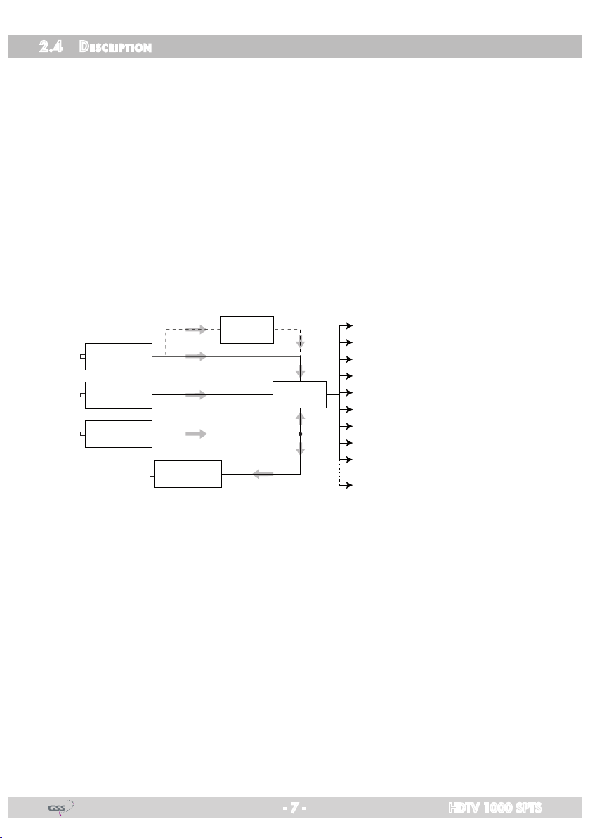
2.4 Description ...................................................................................7
2.5 Software query..............................................................................8
3 Assembly....................................................................................................9
3.1 Installing the cassette......................................................................9
3.2 EMC regulations..........................................................................10
3.3 Cassette overview........................................................................11
3.4 Connecting the cassette................................................................11
3.5 Retrofitting a CA module ..............................................................12
4 The control panel at a glance.....................................................................13
4.1 Menu items.................................................................................13
4.2 Control panel..............................................................................13
5 Programming............................................................................................14
5.1
Programming procedure...................................................................14
5.2 Programming the cassette ............................................................16
Selecting the cassette ...................................................................16
Ethernet parameters .....................................................................17
IP address of the cassette.........................................................17
Address range .......................................................................18
Address of the gateway ..........................................................18
UDP port................................................................................. 19
Input data stream.........................................................................19
LNB oscillator frequency..........................................................20
Input symbol rate....................................................................20
DVB mode.............................................................................20
Input frequency ......................................................................21
Testing the signal to noise ratio.................................................22
Allocating the IP addresses ...........................................................23
Switching the IP address off or on.............................................24
Transmission protocol..............................................................24
Port number ...........................................................................24
Quantity of data packets .........................................................25
Forward error correction .........................................................25

- 3 - HDTV 1000 SPTS
Transmission channel ..............................................................25
IP addresses for services..........................................................26
Allocating services manually....................................................27
Sound options of the service ....................................................28
DVB service information ..........................................................29
Output data rate..........................................................................30
Factory reset ...............................................................................30
Saving settings ............................................................................31
Operation with a CA module........................................................32
PID monitoring .......................................................................32
Configuring the CA module .....................................................32
Descrambling services.............................................................34
6 Final procedures........................................................................................35

- 4 - HDTV 1000 SPTS
1 safety regulations and notes
• Assembly, installationandservicing should becarriedoutby authorised
electricians.
• Switchofftheoperatingvoltageofthesystembeforebeginningwithassem-
bly or service work or pull out the mains plug.
• Donotperforminstallationandserviceworkduringthunderstorms.
• Installthesystemsoitwillnotbeabletovibrate…
- inadust-free,dryenvironment
- insuchamannerthatitisprotectedfrommoisture,fumes,splashingwa-
ter and dampness
- somewhere protected from direct sunlight
- not within the immediate vicinity of heat sources
- in an ambient temperature of 0 °C to +50 °C. In case of the formation of
condensation wait until the system is completely dried.
• Ensurethatthehead-endstationisadequatelyventilated.Donotcoverthe
ventilation slots.
• Bewareofshortcircuits
• Noliabilityisacceptedforanydamagecausedbyfaultyconnectionsor
inappropriate handling.
• Observetherelevantstandards,regulationsandguidelinesontheinstalla-
tion and operation of antenna systems.
• ThestandardsIEC/EN/DINEN50083resp.IEC/EN/DINEN60728must
be observed.
• For further information please read the assembly instructions for the head-
end station used.
• Test the software versions of the head-end station and the cassette and
update them if necessary. The current software versions can be found at
"www.gss.de".
Take action to prevent static discharge when working on the device!
Electronic devices should never be disposed of in the household rubbish. In
accordance with directive 2002/96/EC of the European Parliament and the
European Council from January 27, 2003 which addresses old electronic and
electrical devices, such devices must be disposed of at a designated collection
facility. At the end of its service life, please take your device to one of these
public collection facilities for proper disposal.

- 5 - HDTV 1000 SPTS
2 general information
2.1 PaCking Contents
1 Cassette HDTV 1000 SPTS
2 HF cables
1 Brief assembly instructions
2.2 meaning of the symbols used
Important note
—> General note
• Performingworks
2.3 teChniCal data
The devices meet the following EU directives:
2006/95/EC,2004/108/EC
The product fulfils the guidelines and standards for CE labelling (page 36).
Unless otherwise noted all values are specified as "typical".
HF input
Frequency range: ....................................................... 925…2150MHz
Level range: ............................................................ 60dBμV…80dBμV
Return loss: ..................................................................................> 8 dB
DVB-S modes: ............................................ QPSK 1/2 ,2/3 ,3/4 ,5/6 ,7/8
DVB-S2 modes: ...................QPSK 1/2 ,3/5 ,2/3 ,3/4 ,4/5 ,5/6 ,8/9 ,9/10
8PSK 3/5 ,2/3 ,3/4 ,5/6 ,8/9 ,9/10
Symbol rate DVB-S:.......................................... QPSK: 2…45MSymb/s
Symbol rate DVB-S2:........................................ QPSK:10…30MSymb/s
8PSK:10…31MSymb/s
LAN interface
Standard: .............................................................................100-BASE-T
Data rate:............................................................................... ≤80 MBit
Protocols:.......................................................... UDP(UserDataProtocol),
RTP (Real-Time Transport Protocol)

- 6 - HDTV 1000 SPTS
ASI interfaces
Standard: .....................................................................DIN EN 50083-9
Format: ..............................................................MPEG ISO IEC 13818-1
User data rate:.................................................................2…90Mbit/s
Impedance:.................................................................................... 75 Ω
Level(input/output): ..................................................... 800 mVPP ± 10%
Return loss (input):...............................................>17dB(5…270MHz)
Connections
SAT inputs:.............................................................................2 F sockets
HF output:..........................................................1 IEC socket (no function)
LAN:................................................................................ 1 RJ 45 socket
ASI input: .................................................................1BNCsocket,75Ω
ASI output:................................................................1BNCsocket,75Ω
Connection strip (10-pin): ..................for supply voltages and control circuits
RS 232 socket:..................................... serial interface for software update
Conditional access:...........................several channels can be descrambled.

- 7 - HDTV 1000 SPTS
2.4 desCriPtion
The cassette is a
DVB-S2/SPTS
converter which combines modulated serv-
ices(programmes)inaccordancewiththeDVB-S-/DVB-S2standardanddata
streams supplied via the ASI interface into one data stream in the TPS module.
This is emitted via the LAN interface and can contain up to 16 services. For
operating the cassette in a LAN network it can be assigned its own IP ad-
dress. The cassette is equipped with two tuners. The accompanying channel
strips consist of the digital SAT tuners and the digital signal processing levels.
The resulting data streams from the "
Tuner A
"/"
Tuner B
" channel strips and
from the data streams supplied via the ASI socket (ASI – Asynchronous Serial
Interface according to DIN EN 50083-9) can take up to 16 services and are
each assigned an IP address.
The signal supplied into the ASI input is provided
again via the ASI output.
Principle signal path:
TPS
"Tuner A"
"Tuner B"
CA-ModulCA module
ASI input
ASI output
IP address: Port:
Service 1 212.40.50.90 : 1234
Service 2 212.40.50.91 : 1234
Service 3 212.40.50.92 : 1234
Service 4 212.40.50.93 : 1234
Service 5 212.40.50.94 : 1234
Service 6 212.40.50.95 : 1234
Service 7 212.40.50.96 : 1234
Service 8 212.40.50.97 : 1234
Service 9 212.40.50.98 : 1234
Service 16 212.40.50.105: 1234
Inthehead-endstationdisplay,thechannelstripsofthecassetteareindicated
with "
Bx …A
" ("
Tuner A
") or "
Bx …B
" ("
Tuner B
"). The channel strip "
Tuner
A
" can descramble scrambled channels via a corresponding CA module. The
cassette is controlled with the head-end station control unit.
Two LEDs provide an indication of the signal quality with their colour. The qual-
ity of the received transport stream can also be shown in the display ("
C/N
"
menu).Inanadditionalmenu,thetransmissionofDVBserviceinformation(EIT,
TDT and SDT) or teletext (TXT) can be individually activated or deactivated.
EIT (Event Information Table):
Foreachservice,eventinformationistransmitted(suchasstartingtime,dura-
tion,scramblingetc.)
TDT (Time Date Table):
The transmitted table contains the current time and date.

- 8 - HDTV 1000 SPTS
SDT (Service Description Table):
Information relating to the
scrambling
is also sent with the name of each serv-
ice.
The LEDs for the LAN interface show whether a network connection exists and
whether a data transfer is in progress.
Whenthehead-endstationisswitchedon,thetwo-lineLCdisplayshowsthe
software version of the control unit.
To operate this cassette the software version of the control unit must be "V 44"
or higher. You can find the current operating software for the control unit and
thecassette,thesoftware"BE-Flash" and the current assembly instructions on
the website "www.gss.de".
The cassette is intended for use in the
STANDARD LINE
head-end stations.
2.5 soft ware query
Control unit
If necessary, you can activate the indication of the software version of the
control unit manually:
• Pressanytwokeysonthecontrolunitofthehead-endstationsimultaneously
untilthedisplaygoesdarkandthesoftwareversion,e.g."V 44" appears.
Cassette
After activating the cassette the software version of the cassette is displayed
(see page 16).

- 9 - HDTV 1000 SPTS
3 assembly
3.1 installing the Casset te
– Ensure the head-end station is mounted so it will not be able to vibrate.
Avoid,forexample,mountingthehead-endstationontoaliftshaftorany
other wall or floor construction that vibrates in a similar way.
– Before installing or changing a cassette unplug the power cable from the
mains power socket.
• Removethefasteningscrews1of an unoccupied slot from the bracket of
the head-end station.
• Insertthecassetteinthisslotandpushitintothehousing.
• Alignthecassetteandapplyslightpressuretoconnectittotheconnections
of the board and the HF bus bar.
• Fastenthecassettewiththescrews1.
0°
1
1
CASSETTE
CASSETTE
CASSETTE
CASSETTE
CASSETTE
CASSETTE
CASSETTE
CASSETTE
CASSETTE
CASSETTE
CASSETTE
CASSETTE
MESSAUSGANG
A
ACHTUNG!
Vor dem Cassettenwechsel
unbedingt Netzstecker ziehen!
CAUTION!
Before changing cassettes remove
mains plug!

- 10 - HDTV 1000 SPTS
3.2 emC regulations
To comply with the current EMC regulations, it is necessary to connect the lines
leading in and out of the head-end station using cable terminals.
When mounting the cassette in a head-end station which is installed in a 19"
cabinet, make sure the connections leading in and out for the 19" cabinet are
made using cable terminals.
CLASS
KLASSE
The attenuation of shielding of the connection lines for ASI and antenna must
meet the requirements for "Class A".
• Inserttherequirednumberofcableterminalsintheopeningsprovidedin
the head-end station or in the 19
"
cabinet.
Tighten the nuts on the cable terminals until the teeth on the lock washer have pen-
etrated the exterior coating and a good connection is made between the housing
and cable terminals.

- 11 - HDTV 1000 SPTS
3.3 Cassette overview
5
6
7
8
9
!
@
2
1
4
3
0
1Status LED
of channel strip "
B
"
2 SAT IF input
of channel strip "
B
"
3 Status LED
of channel strip "
A
"
4 SAT IF input
of channel strip "
A
"
5 Status LED of the LAN interface (data transfer)
6
LAN socket
7 Status LED of the LAN interface (network connection)
8 ASI input
9 ASI output
0 Type label
! Slot for a CA module
@ D-SUB socket "RS 232"
The operating software of the cassette can be updated via the
9-pin D-SUB socket "RS 232" using a PC or notebook and the
software "BE-Flash".
You can find the current operating software on the website
"www.gss.de".
3.4 ConneCting the Cassette
• ConnecttheHFconnectionstotheinputs
4
(channel strip "
Tuner A
") and
2
(channel strip "
Tuner B
").
• ConnecttheLANsocket
6
.
—> In order to avoid restrictions of the network data rate (and therefore
possible disturbances) we recommend to operate other applications
likee.g.Internet,VOIPtelephonyetc.inseparatednetworks.
—> Exclusively use "Layer 3 switches", which support the IGMP protocol.
• ConnecttheASIinput
8
and the ASI output
9
to the peripheral ASI devices.

- 12 - HDTV 1000 SPTS
3.5 retrofitting aCa module
The cassette is equipped with a common interface. It allows you to connect a
CA module for various
scrambling
systems and service providers.
Scrambl
ed
channels can only be de
scramble
d with a CA module suitable for the
scram-
bl
ing system and the corresponding smart card. The smart card contains all
theinformationforauthorisation,de
scrambl
ing and subscription.
–
Check with the distributor or manufacturer of the CA module to be used to
ensure that it is suitable for de
scrambl
ing several services.
– The hardware and software of this cassette have been thoroughly prepared
and tested. Any changes made by service providers to the data structures in
the service data might impair or even prevent this function.
– WhenworkingwiththeCAmodule,pleasereadthecorrespondingoperat-
ing manual from the respective provider.
• Insertthesmartcard1into the CA module 2so that the chip 3on the
smart card faces the thicker side (top) of the CA module.
• InserttheCAmoduleintotheguiderailsoftheCAslot4with the top side
of the CA module facing the top side of the cassette.
• PushtheCAmodulewithoutcantingintotheguiderailsoftheCAslot4
and contact it to the common interface.
34 12

- 13 - HDTV 1000 SPTS
4 the Control Panel at aglanCe
4.1 menu items
Programme the
cassette
using the buttons on the control unit of the head-end
station. The two-line display of the control unit then shows the menus.
The parameters and functions to be set are underlined.
Use the key to select the following main menu items:
– Setting Ethernet parameters
– Selecting the input
– Allocating the IP addresses
– Displaying the data rate
– Factory reset
4.2 Control Panel
The key pad on the head-end station is used to scroll through the menus:
scrolls forward through the menus.
select parameters in the menus.
setvalues,initiateactions.
selects sub-menus.
scrolls backward through the menus.
saves all entries.
BE-Remote V41
please wait . . .

- 14 - HDTV 1000 SPTS
5 Programming
5.1
Programming ProCedure
nur Kanalzug “A” mit CA-Modul
only Channel strip “A“ with CA module
Bx 1A
Menu <=
CA
=> Edit
*) Die angezeigte Information ist
abhängig vom verwendeten
CA-Modul.
The information displayed is
dependent on the CA module
used.
Bx 1A 01/03
Information *)
MENU
Bx 1A TV X
. . . .
04/09
X – entschlüsseln
descrambling
0 – nicht entschlüsseln
no descrambling
X / 0
nächster Service
next service
Bx 1A
PID Check
CA
on on / off
BE–Remote
please wait …
V 44
Box 4
V 19
DVBS2-SPTS
– – –
Box 1
………
……
……
Bx 1A
C5-12,S3-24
TWIN-SAT
C07
Böx 4
C5-12,S3-24
TWIN-SAT
C07
Box 5
………
……
……
+
t > 10 s
Bx 4
stat =>
ETHERNET
Options
stat / DHCP
A
Bx 4
192.168. 0. 1
IP-GATEWAY
Bx 4
255.255.255. 0
IP-MASK ▶
◀/
Bx 4
192.168. 0.128
IP-ADDR ▶
◀/
▶
◀/
Bx 4
60000
UDP-PORT ▶
◀/
B
▶
0 … 65535
Ein / On
Tuner A /
Tuner B /
ASI
Bx 4A
11836 -1.8
FREQ
CN 12
Bx 4A
27500 DVB-S
SYMBOL ▶
◀/
▶
◀/
Bx 4A
10600 MHz
LNB ▶
◀/
▶
Bx 4
Tuner A OK
INPUT
=>
DVB-S / QPSK… /
8PSK… / DTV…
▶
◀/Bx 4A
12.0 dB
C/N
(+ 9.6) OK
Anzeige:
Signalqualität
Display:
Signal quality
10600 / 9750
27500 / 22000
IP-OUT 1
…
IP-OUT 16
Bx 4
72.956 Mbps
DATARATE
IP 1
227. 40. 50. 60
OUT-IP
IP 1
7 off
PKTS / FEC ▶
◀/
IP 1
on UDP
MODE / PORT
1234
▶
◀/
▶
Bx 4
Das Erste
IP-OUT 1
=>
on / off
UDP / RTP,
0 … 65535
copy
off / 10/9 … 20/19
Annex A / Annex B
001/015IP 1 TV
Das Erste
Bx 4
EIT TDT TXT SDT
OPTIONS ▶
◀/EIT / eit, TDT / tdt,
TXT / txt, SDT / sdt
(ON / off)
all / 01/…
IP 1
all
AUDIO
copy1 … 7
copy
▶
◀/
auto
M
M
B
A
▶
Bx 4A
Defaults
FACTORY
=>
Bx 4A
STORE
FACTORY
=> M
Werkeinstellwerte
aufrufen
invoke factory defaults
▶
◀
▶
◀/
Bedienhinweise
"blättert" Menüs vorwärts.
"blättert" Menüs rückwärts.
wählen die Eingabeposition
wählt Untermenü
stellen Werte ein,.
speichert alle Eingaben.
1zeigt die Eingabeposition
Operating Hints
scrolls forward through the menu.
scrolls backward through the menu.
select the enter position.
selects a submenu.
set values and triggers actions.
saves all entries.
1shows the enter position
page 15

- 15 - HDTV 1000 SPTS
nur Kanalzug “A” mit CA-Modul
only Channel strip “A“ with CA module
Bx 1A
Menu <=
CA
=> Edit
*) Die angezeigte Information ist
abhängig vom verwendeten
CA-Modul.
The information displayed is
dependent on the CA module
used.
Bx 1A 01/03
Information *)
MENU
Bx 1A TV X
. . . .
04/09
X – entschlüsseln
descrambling
0 – nicht entschlüsseln
no descrambling
X / 0
nächster Service
next service
Bx 1A
PID Check
CA
on on / off
BE–Remote
please wait …
V 44
Box 4
V 19
DVBS2-SPTS
– – –
Box 1
………
……
……
Bx 1A
C5-12,S3-24
TWIN-SAT
C07
Böx 4
C5-12,S3-24
TWIN-SAT
C07
Box 5
………
……
……
+
t > 10 s
Bx 4
stat =>
ETHERNET
Options
stat / DHCP
A
Bx 4
192.168. 0. 1
IP-GATEWAY
Bx 4
255.255.255. 0
IP-MASK ▶
◀/
Bx 4
192.168. 0.128
IP-ADDR ▶
◀/
▶
◀/
Bx 4
60000
UDP-PORT ▶
◀/
B
▶
0 … 65535
Ein / On
Tuner A /
Tuner B /
ASI
Bx 4A
11836 -1.8
FREQ
CN 12
Bx 4A
27500 DVB-S
SYMBOL ▶
◀/
▶
◀/
Bx 4A
10600 MHz
LNB ▶
◀/
▶
Bx 4
Tuner A OK
INPUT
=>
DVB-S / QPSK… /
8PSK… / DTV…
▶
◀/Bx 4A
12.0 dB
C/N
(+ 9.6) OK
Anzeige:
Signalqualität
Display:
Signal quality
10600 / 9750
27500 / 22000
IP-OUT 1
…
IP-OUT 16
Bx 4
72.956 Mbps
DATARATE
IP 1
227. 40. 50. 60
OUT-IP
IP 1
7 off
PKTS / FEC ▶
◀/
IP 1
on UDP
MODE / PORT
1234
▶
◀/
▶
Bx 4
Das Erste
IP-OUT 1
=>
on / off
UDP / RTP,
0 … 65535
copy
off / 10/9 … 20/19
Annex A / Annex B
001/015
IP 1 TV
Das Erste
Bx 4
EIT TDT TXT SDT
OPTIONS ▶
◀/EIT / eit, TDT / tdt,
TXT / txt, SDT / sdt
(ON / off)
all / 01/…
IP 1
all
AUDIO
copy1 … 7
copy
▶
◀/
auto
M
M
B
A
▶
Bx 4A
Defaults
FACTORY
=>
Bx 4A
STORE
FACTORY
=> M
Werkeinstellwerte
aufrufen
invoke factory defaults
▶
◀
▶
◀/
Bedienhinweise
"blättert" Menüs vorwärts.
"blättert" Menüs rückwärts.
wählen die Eingabeposition
wählt Untermenü
stellen Werte ein,.
speichert alle Eingaben.
1zeigt die Eingabeposition
Operating Hints
scrolls forward through the menu.
scrolls backward through the menu.
select the enter position.
selects a submenu.
set values and triggers actions.
saves all entries.
1shows the enter position
page 14

- 16 - HDTV 1000 SPTS
5.2 Programming the Cassette
—> Pressing the button for longer than 2 seconds cancels the
programming procedure. This takes you back to the program item
"Selecting the cassette" from any menu. Any entries that have not
been saved are reset to the previous settings.
—> Entries in the menus can be saved by pressing the key. You are
taken back to the "Selecting the cassette" menu item.
—>
Pressing the
button returns to the previous menus.
• Switchonthehead-endstation
—> The display shows the software version (e.g. V 44)
—> The processor reads the
cassettes
‘ data (approx. 10 seconds).
BE–Remote
please wait …
V 44
t > 10 s
Ein / On
seleCting the Casset te
Box 4
V 19
DVBS2-SPTS
– – –
Box 1
………
……
……
Bx 1A
C5-12,S3-24
TWIN-SAT
C07
Böx 4
C5-12,S3-24
TWIN-SAT
C07
Box 5
………
……
……
+
• Selectthe
cassette
you want to program (e.g. Box 4) by repeatedly pressing
the button if necessary.
—> The display shows e.g. the menu
"Box 4 DVBS2-SPTS"
:
"Box 4" stands for
slot
4
"
DVBS2-SPTS
" type of cassette
"V 19" software version of the cassette

- 17 - HDTV 1000 SPTS
• Pressthe button.
—> The "Ethernet parameters" – "ETHERNET" menu is activated.
ethernet Parameters
In this menu you specify whether the Ethernet parameters for the cassette are
entered automatically by a connected server ("DHCP"),orwhetheryouwant
to enter them manually ("stat").Toassignthecassetteuniquely,eachIPTVcas-
sette must be allocated its own IP address.
Bx 4
stat =>
ETHERNET
Options
• Pressthe buttons to select manual setting ("stat") or automatic setting
("DHCP") of the Ethernet parameters.
• Pressthe
button to activate the setting options
("Options")
.
—> The "IP address of the cassette"
– menu "IP-ADDR" is activated.
iP address of the Cassette
—> Two IP address ranges are used:
– "Hardware" IP addresses, which are used to connect the cassettes in
the network (e.g. 192.168.0.x).
– "IPTV" IP addresses (menu OUT-IP), which are used to send and re-
ceive the IPTV channels (e.g. 227.40.50.x). These IP addresses must
be within the "multicast" range from 224.0.0.0 to 239.255.255.255.
IfyouchoosetoentertheEthernetparametersmanually,settheIPaddressof
the cassette in this menu. If "DHCP"isselected,the"IP-ADDR","IP-MASK" and
"IP-GATEWAY" sub-menus display the parameters that were assigned automati-
callybyaconnectedserver.Ifaserverisnotconnected," 0. 0. 0. 0*"
appearsinthecorrespondingmenu.Thestar"*"inthedisplaymeansthat
the data is provided by a DHCP server.
Bx 4
192.168. 0.128
IP-ADDR

- 18 - HDTV 1000 SPTS
• Usethe
buttons to place the cursor under the digit of the IP address
displayed to be set and use to set the IP address wished.
• Pressthe
button.
—> The "Address range"
– "IP-MASK" menu is activated.
address r ange
In this menu you define the address range for the cassettes connected to the
LAN network.
Bx 4
255.255.255. 0
IP-MASK
• Usethe
buttons to place the cursor under the digit of the IP address
displayed to be set and use to set the IP address wished.
• Pressthe
button.
—> The "Address of the gateway"
– "IP-GATEWAY" menu is activated.
address of the gateway
The address of a gateway (server) can be set in this menu. If no gateway is
used you can skip this setting.
Bx 4
192.168. 0. 1
IP-GATEWAY
• Usethe
buttons to place the cursor under the digit of the IP address
displayed to be set and use to set the IP address wished.
• Pressthe
button.
—> The "UDP port"
– "UDP-PORT" menu is activated.

- 19 - HDTV 1000 SPTS
udP Port
The UDP port setting is required if the cassette needs to be reached externally
tomakethesetting,suchasfromanotherinputfrequency.Thissettingisin-
tended for future functions and can be skipped for this cassette.
Bx 4
60000
UDP-PORT
• Usethe
buttons to place the cursor under the digit of the port number
displayed to be set and use to set the port number wished ("0"…
"65535").
• Pressthe
button.
—> The "Input data stream"
– "
INPUT
" menu is activated.
inPut data stream
In this menu you select the signal source for the selection of the services. The
data streams to be processed are provided by "Tuner A","Tuner B" and the
ASI interface "ASI" .
Bx 4
Tuner A OK
INPUT
=>
• Pressthe buttons to select the signal source of the input data stream
("Tuner A","Tuner B","ASI").
—> "OK" indicates that a transponder is received. If there is no input
signal available "––" is displayed instead of "OK".
• Pressthe button.
—> The "LNB oscillator frequency" – "
LNB
" menu is activated.

- 20 - HDTV 1000 SPTS
lnb osCillator frequenCy
Set the oscillator frequency of the LNB used in this menu.
Bx 4A
10600 MHz
LNB
• Usingthe button the oscillator frequencies "10600" or "9750" can
be selected directly.
• Tosetotheroscillatorfrequenciesusethe buttons to place the cursor
under the digit of the oscillator frequency displayed to be set.
• Press to enter the respective digit of the oscillator frequency of the
LNB used.
• Repeattheprocedurebythequantityofthedigitstobeset.
• Pressthe button.
—> The"Inputsymbolrate,DVBmode"–"SYMBOL" menu is activated.
inPut symbol r ate
dvb mode
The symbol rates of the satellite transponders can be found in the current chan-
neltableofthesatelliteoperator,invarioussatellitemagazinesandinthe
Internet.
ThecassetterecognizesthetransmittedDVBmodeandswitchesoverbetween
the normal QPSK mode (DVB-S) and the DVB-S2 mode. Receiving stations
withDVB-S2mode,wesuggesttopresettheDVBmodetoshortenthetimefor
searching stations.
Bx 4A
27500 DVB-S
SYMBOL
Setting the input symbol rate
• Usingthe button the symbol rates 27500" or "22000" can be
selected directly.
• Tosetothersymbolratesusethe buttons to position the cursor under
the digit of the symbol rate displayed to be set.
• Press
to enter the respective digit of the symbol rate needed.
• Repeattheprocedurebythequantityofthedigitstobeset.
Table of contents
Other GSS Media Converter manuals

GSS
GSS PTIS User manual

GSS
GSS HMPT 1000 T User manual

GSS
GSS HDM 400 P CI User manual

GSS
GSS PHDQ 1000 ASI DF User manual

GSS
GSS SDA 521 User manual

GSS
GSS HDMT 1000 SPTS User manual

GSS
GSS SOQD 104 User manual

GSS
GSS Compact Classic STC 4-16 IPS CI User manual

GSS
GSS PTDT 9200 User manual

GSS
GSS SOQ 100 User manual
Popular Media Converter manuals by other brands

AudioQuest
AudioQuest DragonFly Cobalt manual

Tektronix
Tektronix TDC5 user manual

Teledyne Lecroy
Teledyne Lecroy OE695G Operator's manual

GoMax Electronics
GoMax Electronics MX-3004F user manual

Rockwell Automation
Rockwell Automation Allen-Bradley 1606-XLDF240F installation instructions

Monoprice
Monoprice Blackbird 9140A-PCA user manual