GSS PHDQ 8008 TSR User manual

English
CLASS
KLASSE
GSS
Grundig SAT Systems GmbH
Beuthener Strasse 43
D-90471 Nuremberg
Phone: +49 (0) 911 / 703 8877
Fax: +49 (0) 911 / 703 9210
E-mail: [email protected]
Internet: http://www.gss.de
HDTV Digital QAM
PHDQ 8008 TSR

- 2 - PHDQ 8008 TSR
Contents
1 Safety regulations and notes..............................................................................4
2 General information ..........................................................................................5
2.1 Packing contents................................................................................... 5
2.2 Meaning of the symbols used................................................................. 5
2.3 Technical data...................................................................................... 5
2.4 Description........................................................................................... 6
2.4.1 Input signal path ......................................................................... 6
2.4.2 Output signal path "OUTROUTE".................................................. 7
Menu setting "ASI => ASI"........................................................... 7
Menu setting "1 => ASI ASI => MA" .......................................... 7
Menu setting "2 => ASI ASI => MB"........................................... 7
2.4.3 General ..................................................................................... 8
2.5 Software query..................................................................................... 8
3 Assembly ..........................................................................................................9
3.1 Installing the cassette............................................................................. 9
3.2 EMC regulations................................................................................... 9
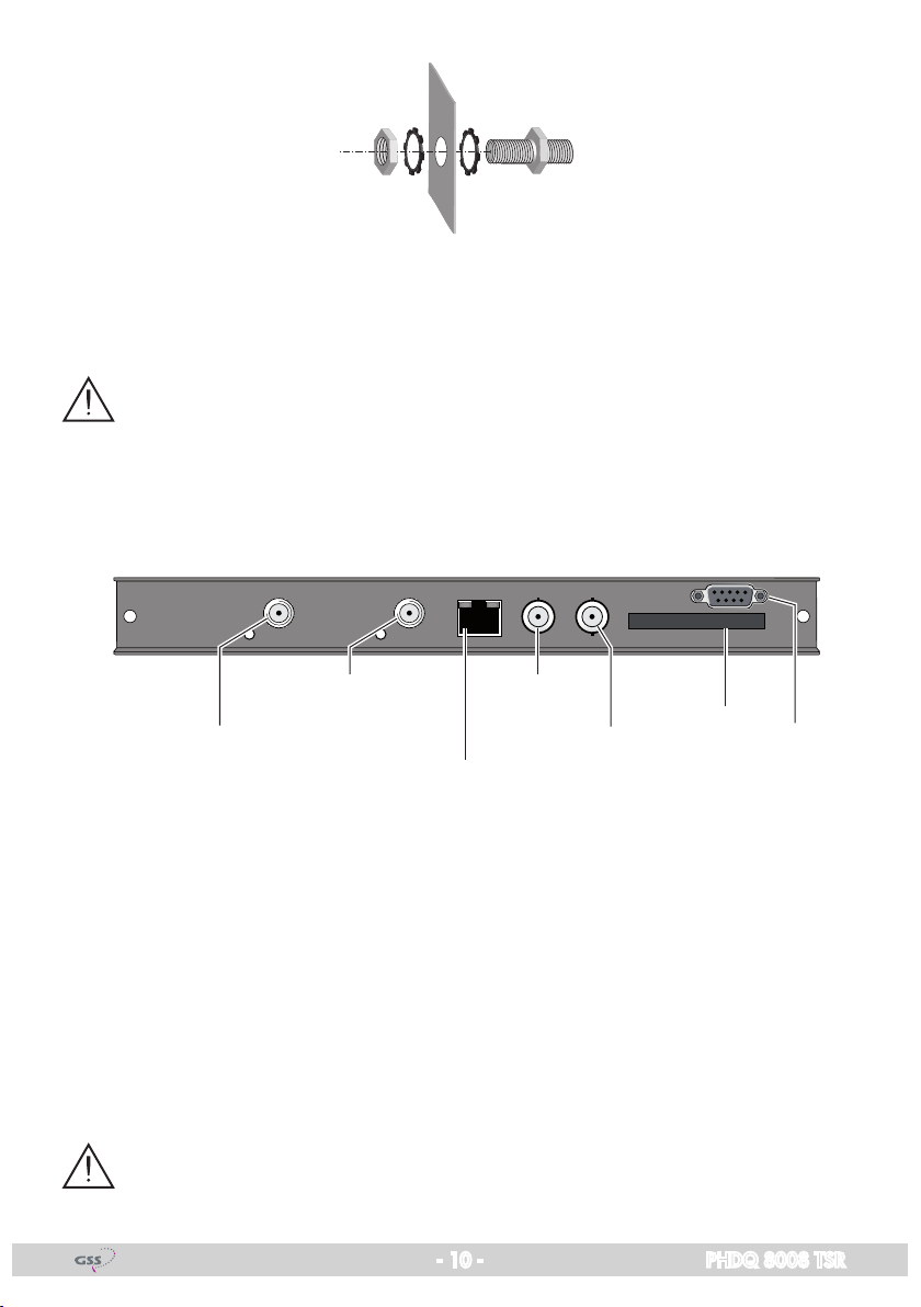
3.3 Connecting the cassette ....................................................................... 10
4 The control panel at a glance ...........................................................................11
4.1 Menu items ........................................................................................ 11
4.2 Control panel ..................................................................................... 11
5 Programming ..................................................................................................12
5.1 Preparation........................................................................................ 12
5.2
Notes on level setting.......................................................................... 12
5.3 Programming procedure ...................................................................... 13
5.4 Programming the cassette ................................................................... 15
Selecting the cassette .......................................................................... 15
Selecting the output signal path ............................................................ 16
Setting the ASI transfer rate.................................................................. 16
Setting the ASI options ...........................................................................17
Selecting the channel strip ................................................................... 17
Selecting channel / frequency setting.................................................... 18
Setting the output channel.................................................................... 19
Setting the output frequency ................................................................. 19
Switching the modulator off or on ......................................................... 19
Adjusting the output levels of the channel strips....................................... 20

- 3 - PHDQ 8008 TSR
Setting the LNB oscillator frequency ...................................................... 20
Setting the input symbol rate ................................................................ 21
Setting the DVB mode.......................................................................... 21
Setting the input frequency................................................................... 21
Testing the signal to noise ratio............................................................. 22
Setting the PSI .................................................................................... 23
Setting the QAM modulation
..................................................................24
Inverting the user signal....................................................................... 24
Setting stuffing.................................................................................... 24
Setting a substitute signal..................................................................... 26
Factory reset ...................................................................................... 26
Saving settings ................................................................................... 27
6 Channel and frequency tables..........................................................................28

- 4 - PHDQ 8008 TSR
1 Safety regulations and notes
• Assembly,installationandservicingshouldbe carried outbyauthorised
electricians.
• Switchofftheoperatingvoltageofthesystembeforebeginningwithassem-
bly or service work or pull out the mains plug.
• Donotperforminstallationandserviceworkduringthunderstorms.
• Installthesystemsoitwillnotbeabletovibrate…
- inadust-free,dryenvironment
- insuchamannerthatitisprotectedfrommoisture,fumes,splashingwa-
ter and dampness
- somewhere protected from direct sunlight
- not within the immediate vicinity of heat sources
- in an ambient temperature of 0 °C to +50 °C. In case of the formation of
condensation wait until the system is completely dried.
• Ensurethatthehead-endstationisadequatelyventilated.Donotcoverthe
ventilation slots.
• Bewareofshortcircuits
• Noliabilityisacceptedforanydamagecausedbyfaultyconnectionsor
inappropriate handling.
• Observetherelevantstandards,regulationsandguidelinesontheinstalla-
tion and operation of antenna systems.
• The standards IEC/EN/DINEN50083 and IEC/EN/DINEN60728 must
be observed.
• For further information please read the assembly instructions for the head-
end station used.
• Test the software versions of the head-end station and the cassette and
update them if necessary. The current software versions can be found at
"www.gss.de".
Take action to prevent static discharge when working on the device!
Electronic devices should never be disposed of in the household rubbish. In
accordance with directive 2002/96/EC of the European Parliament and the
European Council from January 27, 2003 which addresses old electronic and
electrical devices, such devices must be disposed of at a designated collection
facility. At the end of its service life, please take your device to one of these
public collection facilities for proper disposal.

- 5 - PHDQ 8008 TSR
2 General information
2.1 Packing contents
1 Cassette PHDQ 8008 TSR
2 HF cables
1 CD (assembly instructions)
1 Brief assembly instructions
1 Measuring log
2.2 Meaning of the symbols used
Important note
—> General note
• Performingworks
2.3 Technical data
The devices meet the following EU directives:
2006/95/EC, 2004/108/EC
The product fulfils the guidelines and standards for CE labelling.
Unless otherwise noted all values are specified as "typical".
HF input
Frequency range:......................................................... 925…2150MHz
Level range: .............................................................60dBμV…80dBμV
DVB-S modes: ..............................................DVB-S 1/2 , 2/3 , 3/4 , 5/6 , 7/8
DVB-S2 modes: ....................QPSK 1/2 , 3/5 , 2/3 , 3/4 , 4/5 , 5/6 , 8/9 , 9/10 ,
8PSK 3/5 , 2/3 , 3/4 , 5/6 , 8/9 , 9/10
Symbol rate DVB-S:...........................................QPSK: 2 … 45 MSymb/s
Symbol rate DVB-S2:.........................................QPSK: 10 … 30 MSymb/s
8PSK: 10 … 31 MSymb/s
HF output
Channels: .............................................................................S21…C69
Frequency range:...............................................42.0MHz…860.0MHz
Output level: ............................................................................. 97 dBμV
Output impedance:......................................................................... 75 Ω
Output symbol rate: ......................................................1 … 7.5 MSymb/s

- 6 - PHDQ 8008 TSR
Connections
SAT inputs:.............................................................................2 F sockets
HF output:............................................................................ 1 IEC socket
ASI input: .................................................................1BNCsocket,75Ω
ASI output:................................................................1BNCsocket,75Ω
Connection strip (10-pin):...................for supply voltages and control circuits
RS 232 socket: ..................................... serial interface for software update
2.4 Description
ThetwintransmodulatorcassetteisaQPSK-converter,whichconvertsallsta-
tions transmitted according to DVB-S /
DVB-S2
standard into two QAM-modu-
lated cable signals.
The
cassette
has two digital SAT inputs and an HF output.
Additionally it is equipped with an ASI input and an ASI output (ASI – Asyn-
chronous Serial Interface acc. DIN EN 50083-9).
The transport stream fed via the ASI socket
(TS ASI)
is inserted into the transport
streams of the receiving stages via the TPS module.
In this way data can be
added or removed. T
he output signal path is set in the menu item
"OUTROUTE"
.
2.4.1 Input signal path
Transport stream 2
SAT input ”A“
ASI input
SAT input ”B“
Transport stream ASI
TPS
TPS
TS B
TS A
TS ASI
Transport stream 1
Receiving stage
"A"
Receiving stage
"B"

- 7 - PHDQ 8008 TSR
2.4.2 Output signal path "OUTROUTE"
Menu setting "ASI => ASI"
Transport stream 1 is made available via modulator "A",transportstream2
via modulator "B" and the transport stream ASI from the ASI input via the ASI
output.
Transport stream 1
Transport stream 2
HF output
Transport stream ASI
Modulator
"B"
ASI output
Modulator
"A"
Combiner
Menu setting "1 => ASI ASI => MA"
Transportstream1ismadeavailableviatheASIoutput,transportstream2via
modulator "B" and the transport stream ASI from the ASI input via modulator
"A" (MA).
Transport stream 1 ASI output
HF output
Modulator
"B"
Modulator
"A"
Combiner
Transport stream ASI
Transport stream 2
Menu setting "2 => ASI ASI => MB"
Transport stream 1 is made available via modulator "A",transportstream2via
the ASI output and the transport stream ASI from the ASI input via modulator
"B" (MB).
ASI output
Transport stream 1
Transport stream 2
Transport stream ASI
HF output
Modulator
"B"
Modulator
"A"
Combiner

- 8 - PHDQ 8008 TSR
2.4.3 General
Using the software
PSW 1000
the transport streams of the cassette can be
processed.Thismeansthatthedata(PSI,NIT, SIetc.)primary containedin
the transport stream can be replaced by the data processed with the software
PSW 1000
.
The cassette is equipped with two channel strips ("
A
" and "
B
"). The channel
stripsconsistofthedigitaltuners,thedigitalsignalpreparationunitsandthe
output converter.
The channel strips are indicated in the head-end station dis-
play with "Bx …A" and "Bx …B". The control of the cassette takes place via
the control unit of the head-end station.
Two LEDs indicate if the respective channel strip is switched on (LED illumi-
nates)oroff,andalsoprovideanindicationofthesignalqualitybasedon
their colour. Additionally the quality of the transport stream received is dis-
played ("CN…").
The HF output signals are sent through the HF output of the cassette to the out-
put collector. The common output level of the channel strips can be set at the
output collector. Additionally a transport stream is made available via the ASI
output dependent on the signal path set.
Whenthehead-endstationisswitchedon,thetwo-lineLCdisplayshowsthe
software version of the control unit.
To operate this cassette the software version of the control unit must be "V 41"
or higher. You can find the current operating software for the control unit and
thecassette,thesoftware"BE-Flash" and the current assembly instructions on
the website "www.gss.de".
The cassette is designed for use in the following head-end stations:
PSU12,PSU8,PGT8 and PST 19-1.
2.5 Software query
Control unit
If necessary, you can activate the indication of the software version of the
control unit manually:
• Pressanytwokeysonthecontrolunitofthehead-endstationsimultaneously
untilthedisplaygoesdarkandthesoftwareversion,e.g."V 41" appears.

- 9 - PHDQ 8008 TSR
3 Assembly
3.1 Installing the cassette
– Ensure the head-end station is mounted so it will not be able to vibrate.
Avoid,forexample,mountingthehead-endstationontoaliftshaftorany
other wall or floor construction that vibrates in a similar way.
– Before installing or changing a cassette unplug the power cable from the
mains power socket.
• Removethefasteningscrews1of an unoccupied slot from the bracket of
the head-end station.
• Insertthecassetteinthisslotandpushitintothehousing.
• Alignthecassetteandapplyslightpressuretoconnectittotheconnections
of the board and the HF bus bar.
• Fastenthecassettewiththescrews1
0°
1
1
KASSETTE
KASSETTE
KASSETTE
KASSETTE
KASSETTE
KASSETTE
KASSETTE
KASSETTE
KASSETTE
KASSETTE
KASSETTE
KASSETTE
AUSGANG
max. 90 dBµV
ACHTUNG!
Vor dem Kassettenwechsel
unbedingt
denNetzstecker ziehen.
CAUTION!
Before
changing cassettes remove
mains plug.
Grundig SAT Systems
3.2 EMC regulations
To comply with the current EMC regulations, it is necessary to connect the lines
leading in and out of the head-end station using cable terminals.
When mounting the cassette in a head-end station which is installed in a 19"
cabinet, make sure the connections leading in and out for the 19" cabinet are
made using cable terminals.
CLASS
KLASSE
The attenuation of shielding of the connection lines must meet the requirements
for "Class A".

- 10 - PHDQ 8008 TSR
• Inserttherequirednumberofcableterminalsintheopeningsprovidedin
the head-end station or in the 19
"
cabinet.
—> Cable terminals are not included in the scope of delivery.
Tighten the nuts of the cable terminals until the teeth on the lock washers
put un-
der
have penetrated the exterior coating and a good connection is made between
the housing
/ 19" cabinet
and cable terminals.
3.3 Connecting the cassette
RS 232
7
6
3
ASI output
5
SAT input "A"
2
ASI input
4
SAT input "B"
1
•
Connect the SAT input cables to the sockets "
SAT input A
" 2(channel strip
"A") and "
SAT input B
" 1(channel strip "B").
• ConnecttheASIsockets4and 5.
•
Connect the head-end station to the mains power supply.
7 "RS 232"socket
The operating software of the
cassette
can be updated via the 9-Pin D-
SUB socket "RS 232" using a PC or laptop and the software "BE-Flash".
You can find the current operating software and the software "BE-Flash"
on the website "www.gss.de".
The LAN socket
3
and the slot for a CA module
6
are without function.

- 11 - PHDQ 8008 TSR
4 The control panel at a glance
4.1 Menu items
Program the
cassette
using the buttons on the control unit of the head-end sta-
tion. The two-line display of the control unit then shows the menus.
The parameters and functions to be set are underlined.
Use the key to select the following main menu items:
– Output signal path
– Channel strip
– Selecting channel / frequency setting
– Output channel / output frequency
– Output level
– LNB oscillator frequency
– Input symbol rate
– Input frequency
– PSI
– QAM modulation
– Stuffing
– Substitute signal
– Factory reset
4.2 Control panel
The key pad on the head-end station is used to scroll through the menus and
menu items one at a time:
scrolls forward through the menus.
select parameters in the menus.
setvalues,initiateactions.
selects sub-menus.
scrolls backward through the menus.
saves all entries
BE-Remote V41
PROFESSIONAL

- 12 - PHDQ 8008 TSR
5 Programming
5.1 Preparation
• ConnectthetestreceivertotheHFoutputorthetestoutputofthehead-end
station.
• Settheoutputchannel/outputfrequencyofthe
cassette
(see page 19) and
adjust the TV test receiver to this channel.
•
Switch on the channel strip (modulator) if necessary (see page 19). For each
channel strip, there is a status LED which indicates if the channel strip is
switched on.
Status LED
Channel strip
"B"
Status LED
Channel strip
"A"
• Balancetheoutputlevelsofthechannelstrips"A" and "B" if the difference
in level is ≥ 1 dB (page 20).
5.2
Notes on level setting
In order to prevent interference within the head-end station and the cable
system,theoutputlevelofthecassettemustbeloweredby10dBcomparedto
analoguecassettesat64QAM,andby4dBcomparedtoanaloguecassettes
at 256 QAM.
• Measuretheoutputlevelsoftheothercassettesandtunethemtoauniform
output level using the appropriate level controls or software dependent on
the head-end station used. Please regard the assembly instructions of the
respective head-end station.

- 13 - PHDQ 8008 TSR
5.3 Programming procedure
Ein / On
BE–Remote
PROFESSIONAL
V 41
Box 4
V 12
DVBS2-TSR
– – –
+
t > 10 s
A
Bx 4A
Freq.
OUTPUT
Freq. / Channel
Bx 4A
850,00 MHz
OUTPUT
on
Bx 4A
27500
SYMBOL
DVB-S
Bx 4A
11835 -0.6
FREQ
CN 15
▶
◀/
▶
◀/
▶
◀/
on / off
▶
◀/
▶
◀/
Bx 4A
-3 dB
LEVEL
Bx 4A
10600 MHz
LNB
0 … -10 dB
Bx 4A
15.0 dB
C/N
(+ 11.0) OK
Anzeige: Signalqualität
Display: Signal quality
▶
◀/
DVB-S / DVB-S 2 …
Bx 4A
OFF
PSI
Bx 4A
SR=6900 (6325)
STUFFING
Bx 4A
Single Carrier
FAILURE
Bx 4A
256-QAM
QAM
normal
▶
◀/
▶
◀/
4 … 256 normal / inverse
Single Carrier / Null Packets / Tables
OFF … MIX+TABLES+EIT
Bx 4
Line A <=
LINE
=> Line B Line A / Line B
B
1=>ASI ASI=>MA
2=>ASI ASI=>MB
ASI=>ASI
Bx 4
ASI=>ASI
OUTROUTE Bx 4
108000 KBits
ASI RATE
188 / 204
positive / negative
continuous / burst
Bx 4
188 pos. cont.
ASI OPTION
▶
◀/
▶
◀/
Box 1
..............
..............
..............
Bx 1A
C5-12,S3-24
TWIN-SAT
C07
Böx 4
C5-12,S3-24
TWIN-SAT
C07
Box 5
..............
..............
..............
M
B
A
▶
Bx 4A
Defaults
FACTORY
=>
Bx 4A
STORE
FACTORY
=> M
auf Werkseinstellung
zurücksetzen und speichern
reset to factory defaults
and store
Page 14
Page 14

- 14 - PHDQ 8008 TSR
Ein / On
BE–Remote
PROFESSIONAL
V 41
Box 4
V 12
DVBS2-TSR
– – –
+
t > 10 s
A
Bx 4A
Freq.
OUTPUT
Freq. / Channel
Bx 4A
850,00 MHz
OUTPUT
on
Bx 4A
27500
SYMBOL
DVB-S
Bx 4A
11835 -0.6
FREQ
CN 15
▶
◀/
▶
◀/
▶
◀/
on / off
▶
◀/
▶
◀/
Bx 4A
-3 dB
LEVEL
Bx 4A
10600 MHz
LNB
0 … -10 dB
Bx 4A
15.0 dB
C/N
(+ 11.0) OK
Anzeige: Signalqualität
Display: Signal quality
▶
◀/
DVB-S / DVB-S 2 …
Bx 4A
OFF
PSI
Bx 4A
SR=6900 (6325)
STUFFING
Bx 4A
Single Carrier
FAILURE
Bx 4A
256-QAM
QAM
normal
▶
◀/
▶
◀/
4 … 256 normal / inverse
Single Carrier / Null Packets / Tables
OFF … MIX+TABLES+EIT
Bx 4
Line A <=
LINE
=> Line B Line A / Line B
B
1=>ASI ASI=>MA
2=>ASI ASI=>MB
ASI=>ASI
Bx 4
ASI=>ASI
OUTROUTE Bx 4
108000 KBits
ASI RATE
188 / 204
positive / negative
continuous / burst
Bx 4
188 pos. cont.
ASI OPTION
▶
◀/
▶
◀/
Box 1
..............
..............
..............
Bx 1A
C5-12,S3-24
TWIN-SAT
C07
Böx 4
C5-12,S3-24
TWIN-SAT
C07
Box 5
..............
..............
..............
M
B
A
▶
Bx 4A
Defaults
FACTORY
=>
Bx 4A
STORE
FACTORY
=> M
auf Werkseinstellung
zurücksetzen und speichern
reset to factory defaults
and store
Page 13

- 15 - PHDQ 8008 TSR
5.4 Programming the cassette
—> Pressing the button for longer than 2 seconds cancels the pro-
gramming procedure. This takes you back to the program item "Selecting
the cassette" from any menu. Any entries that have not been saved are
reset to the previous settings.
—> Entries in the menus can be saved by pressing the key. You are taken
back to the "Selecting the cassette" menu item.
• Switchonthehead-endstation
—> The display shows the software version (e.g. V 41)
—> The processor reads the
cassettes
‘data(approx.10seconds).
Ein / On
BE–Remote
PROFESSIONAL
V 41
t > 10 s
Selecting the cassette
Box 4
V 12
DVBS2-TSR
– – –
+
Box 1
..............
..............
..............
Bx 1A
C5-12,S3-24
TWIN-SAT
C07
Böx 4
C5-12,S3-24
TWIN-SAT
C07
Box 5
..............
..............
..............
• Selectthe
cassette
you want to program (e.g. Box 4) by repeatedly pressing
the button if necessary.
—> The display shows e.g. the menu
"Box 4 DVBS2-TSR"
:
"Box 4" stands for
slot
4
"DVBS2-TSR"Type of cassette
"V 12"Software version of the cassette
• Pressthe button.
—> The "Selecting the output signal path" – "OUTROUTE" menu is activated.

- 16 - PHDQ 8008 TSR
Selecting the output signal path
In this menu you define the signal path of the output transport streams.
Menu setting "ASI => ASI" (page 7).
Menu setting "1 => ASI ASI => MA" (page 7).
Menu setting "2 => ASI ASI => MB" (page 7).
Bx 4
ASI=>ASI
OUTROUTE
• Usethe buttons to select the signal path wished.
• IfyoudonotwanttodoASIsettings,pressthe button.
—> The "Selecting the channel strip" – "LINE" menu is activated
(page 17).
• Pressthe button.
—> The "Setting the ASI transfer rate" – "ASI RATE" menu is activated.
Setting the ASI transfer rate
In this menu you set the transfer rate for the ASI component connected.
For this setting please take the required information from the documentation
(technical data) of the ASI component to be connected.
Bx 4
108000 KBits
ASI RATE
• Usethe
buttons to place the cursor under the digits to be set for the
transfer rate then use the buttons to set the transfer rate wished.
• Pressthe button.
—> The "Setting the ASI options"
– "ASI OPTION" menu is activated.

- 17 - PHDQ 8008 TSR
Setting the ASI options
Inthismenuyoudefinethesizeofthedatapackets,theirpolarityandthetype
of transmission.
For this setting please take the required information from the documentation
(technical data) of the ASI component to be connected.
Bx 4
188 pos. cont.
ASI OPTION
• Pressthe buttonstosetthesizeofthedatapackets("188" or "204"
bits).
• Ifthepolarityofthedatatobetransmittedhastobechanged,pressthe
buttons
to place the cursor under "pos." (positive – standard) and
using the buttons set to "neg." (negative).
• Tochangethetypeoftransmissionpressthe
buttons to
position the
cursor under "cont." (continuous – standard) and using the buttons
set to "burst".
—> Setting "cont."
The data packets of the user data are collected to a great data packet in
the transport stream.
—> Setting "burst"
The data packets of the user data are spaced out evenly in the transport
stream.
• Pressthe button.
—> The "Selecting the channel strip" – "LINE" menu is activated.
Selecting the channel strip
Bx 4
Line A <=
LINE
=> Line B
• Bypressing
select channel strip "A" ("Line A") or channel strip "B" ("Line
B") by pressing the
button
.

- 18 - PHDQ 8008 TSR
• Pressthe button.
—> The "Selecting channel / frequency setting" – "OUTPUT" menu is acti-
vated.
Selecting channel / frequency setting
Inthismenu,youcanchoosethechannelorfrequencysettingfortheadjust-
ment of the HF output. The channel setting covers the range of channels S21
…C69,thefrequencysettingcoverstherangefrom42.0MHzto860.0MHz.
The QAM signal is normally transmitted with a bandwidth of 8 MHz. This
means that you can only use the channel centre frequency of the existing
channel raster in the range of channels S21 … C69 (frequency raster 8 MHz).
The CCIR channel raster is 7 MHz in the range of the lower frequency bands
(channels C2 … S20). Therefore the frequency setting is used here. If one uses
the existing channel raster of 7 MHz in these channel ranges, this will result in
interference (overlapping) with the 8 MHz QAM signal packages, thus caus-
ing transmission problems.
For programming in these channel ranges and in the frequency ranges below
them,werecommendstartingwithchannelS21/306MHzgoingbackin
stepsof8MHz(seefrequencytableonpage28),orreducingthebandwidth
of the QAM output signal by removing stations using the software PSW 1000.
Bx 4A
Freq.
OUTPUT
• Use to select channel setting "Channel" or frequency setting "Freq.".
• Pressthe button.
—> The "Setting the output channel" or "Setting the output frequency" –
"OUTPUT" menu is activated.

- 19 - PHDQ 8008 TSR
Setting the output channel
In this menu you set the output channel of the channel strip. Additionally the
modulator of the channel strip can be switched off or on.
Bx 4A
C68
OUTPUT
on
•
Use the buttons to set the output channel.
Setting the output frequency
In this menu you set the output frequency of the channel strip
(42.0…860.0
MHz)
. Additionally the modulator
of the channel strip
can be switched off or on.
Bx 4A
850,00 MHz
OUTPUT
on
• Usethe
buttons to place the cursor under the digits to be set for the
frequency display then use to set the output frequency wished.
Switching the modulator off or on
• Toswitchoffthemodulatorplacethecursorunder"on" using the button
and switch "off" the modulator of the channel strip using the buttons.
—>
The switched off modulator is indicated by " - - - " in the display.
—> The status LED is switched off (see also page 12).
• Ifthemodulatorisswitched"off" use the to switch it "on".
• Pressthe button.
—>
The "Adjusting the output levels of the channel strips"
–
"LEVEL" menu is
activated.

- 20 - PHDQ 8008 TSR
Adjusting the output levels of the channel strips
This menu item is used to set the output levels of the modulators of the channel
strips "A" and "B"to the same value.
Bx 4A
-3 dB
LEVEL
• Measureandnotedowntheoutputlevelofthechannelstrip.
• Byrepeatedlypressingthe button scroll back to the "Selecting the
channel strip" menu.
• Selecttheotherchannelstrip
(page 17) and set the following menu items:
• "Selectingchannel/frequencysetting",page18
• "Settingtheoutputchannel"or"Settingtheoutputfrequency",page19
• Switchonthemodulatorifnecessary,page19
• Measureandnotedowntheoutputlevel.
• Activatethe
"LEVEL" menu of the channel strip with the higher output level.
• By pressi
ng adjust the higher output level of one channel strip to
the lower output level of the other channel strip incrementally from "0
" to
"
–10 dB".
• Pressthe button.
—> The "Setting the LNB oscillator frequency" – "
LNB
" menu is activated.
Setting the LNB oscillator frequency
Set the oscillator frequency of the LNB used in this menu.
Bx 4A
10600 MHz
LNB
• Use to place the cursor under the digits of the frequency display to
be set.
• Press to enter the oscillator frequency of the LNB used.
• Pressthe button.
—> The "Setting the input symbol rate" – "SYMBOL" menu is activated.
Other manuals for PHDQ 8008 TSR
1
Table of contents
Other GSS Media Converter manuals

GSS
GSS PTDT 9200 User manual

GSS
GSS HRC 300 AV User manual

GSS
GSS HDTV 1000 S User manual

GSS
GSS PEDQ 3005 QMX User manual

GSS
GSS HDE 400 User manual

GSS
GSS Compact Classic STC 4-16 IPS CI User manual

GSS
GSS PCIM 1000 User manual

GSS
GSS HDM 400 P CI User manual

GSS
GSS HDMT 1000 MPTS User manual

GSS
GSS PHDQ 6100 CI TPS User manual

GSS
GSS PMDQ 1000 User manual

GSS
GSS PTIM 1000 User manual

GSS
GSS PTDT 1000 User manual

GSS
GSS HRC 300 AV User manual

GSS
GSS HMPT 1000 C User manual

GSS
GSS PTDQ 1000 ASI LAN User manual

GSS
GSS PHDQ 1000 ASI DF User manual

GSS
GSS STI 1916 CT User manual

GSS
GSS HDTV 1000 MPTS User manual

GSS
GSS HDE 166 User manual