GSS PTDQ 1000 ASI LAN User manual

English
CLASS
KLASSE
GSS
Grundig SAT Systems GmbH
Beuthener Strasse 43
D-90471 Nuremberg
Phone: +49 (0) 911 / 703 8877
Fax: +49 (0) 911 / 703 9210
E-mail: [email protected]
Internet: http://www.gss.de
PTDQ 1000 ASI LAN
PTDQ 1001
COFDM Digital QAM

- 2 - PTDQ 1000 ASI LAN / PTDQ 1001
Contents
1 Safety regulations and notes .....................................................................................4
2 General information .................................................................................................5
2.1 Packing contents..........................................................................................5
2.2 Meaning of the symbols used........................................................................5
2.3 Technical data.............................................................................................5
2.4 Description .................................................................................................6
2.4.1 Input signal path “INROUTE” ..............................................................6
2.4.1.1 Menu setting “A+ASI = 1 B+ASI = 2”...................................6
2.4.1.2 Menu setting “A+B+ASI = 1 ASI = 2”...................................7
2.4.2 Output signal path “OUTROUTE” ........................................................7
2.4.2.1 Menu setting “ASI => ASI”....................................................7
2.4.2.2 Menu setting “1 => ASI ASI => MA” ...................................7
2.4.2.3 Menu setting “2 => ASI ASI => MB”....................................8
2.4.3 General ...........................................................................................8
2.5 Software query............................................................................................9
2.6 How the TPS module works...........................................................................9
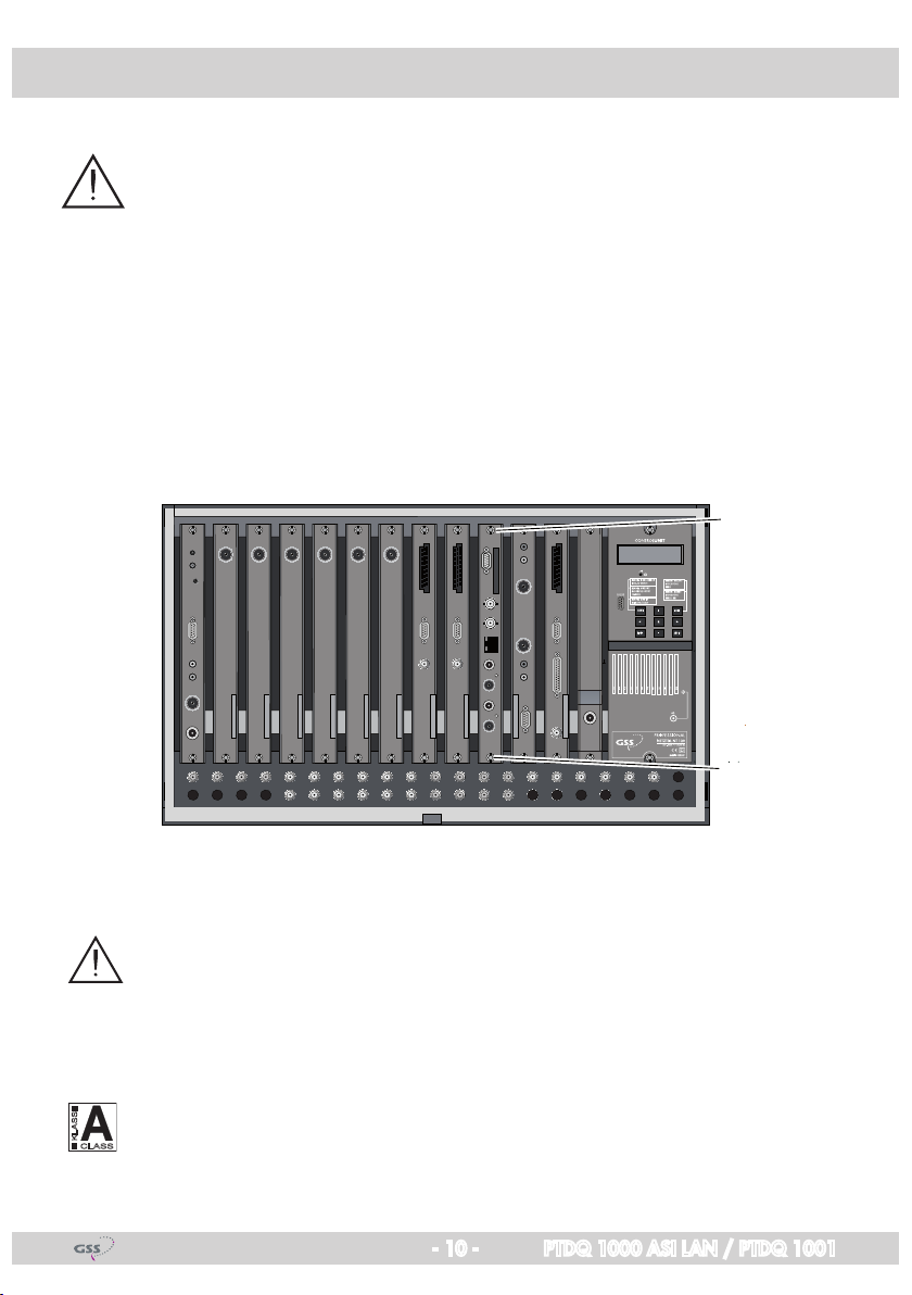
3 Assembly ...............................................................................................................10
3.1 Installing the cassette..................................................................................10
3.2 EMC regulations........................................................................................10
3.3 Overview of the cassette ............................................................................11
3.4 Connecting the cassette..............................................................................12
3.5 Retrofitting a CA module ............................................................................12
4 The control panel at a glance ..................................................................................13
4.1 Menu items...............................................................................................13
4.2 Control panel............................................................................................13
5 Programming .........................................................................................................14
5.1 Preparation...............................................................................................14
5.2 Programming procedure.............................................................................15
5.2.1 Channel strips “A” (without CA module) and “B”.................................15
5.2.2 Channel strip “A” with CA module ....................................................18
5.3 Programming the cassette ..........................................................................19
Selecting the cassette .................................................................................19
Selecting the input signal path.....................................................................20
Selecting the output signal path ...................................................................20
Setting the ASI transfer rate.........................................................................21
Setting the ASI options ...............................................................................22
Selecting the channel strip ..........................................................................23
Selecting channel / frequency setting...........................................................23
Setting the output channel...........................................................................24
Setting the output frequency ........................................................................24
Switching the modulator off or on ................................................................25
Adjusting the output levels of the channel strips .............................................25
Setting the input channel ............................................................................26

- 3 - PTDQ 1000 ASI LAN / PTDQ 1001
Setting the hierarchical modulation ..............................................................27
Setting the station filter ...............................................................................28
Setting the QAM modulation
......................................................................33
Inverting the user signal..............................................................................33
Setting stuffing...........................................................................................34
Setting a substitute signal in the case of an incorrect input signal ....................35
Setting the transport stream ID and the ORGNET-ID .......................................36
Setting the network/operator identification ...................................................38
Deleting a PID ...........................................................................................39
Renaming a PID.........................................................................................39
Saving settings ..........................................................................................40
5.3.1 Operation with a CA module............................................................40
Setting the encoding (only PTDQ 1001) .............................................41
Setting the PID monitoring ................................................................41
Configuring the CA module ..............................................................42
Setting the station filter.....................................................................43
6 Final procedures.....................................................................................................45
7 Channel and frequency tables .................................................................................46

- 4 - PTDQ 1000 ASI LAN / PTDQ 1001
1 Safety regulations and notes
UÊ ÃÃiLÞ]ÊÃÌ>>ÌÊ>`ÊÃiÀÛV}ÊÃÕ`ÊLiÊV>ÀÀi`ÊÕÌÊLÞÊ>ÕÌÀÃi`Ê
electricians.
ÊUÊ -ÜÌVÊvvÊÌiÊ«iÀ>Ì}ÊÛÌ>}iÊvÊÌiÊÃÞÃÌiÊLivÀiÊLi}}ÊÜÌÊ>Ã-
sembly or service work or pull out the mains plug.
Ê UÊ ÊÌÊ«iÀvÀÊÃÌ>>ÌÊ>`ÊÃiÀÛViÊÜÀÊ`ÕÀ}ÊÌÕ`iÀÃÌÀð
Ê UÊ ÃÌ>ÊÌiÊÃÞÃÌiÊÃÊÌÊÜÊÌÊLiÊ>LiÊÌÊÛLÀ>Ìio
Ê Ê Ê Ê>Ê`ÕÃÌvÀii]Ê`ÀÞÊiÛÀiÌ
Ê Ê Ê ÊÊÃÕVÊ>Ê>iÀÊÌ>ÌÊÌÊÃÊ«ÀÌiVÌi`ÊvÀÊÃÌÕÀi]ÊvÕiÃ]Êë>Ã}Ê
water and dampness
- somewhere protected from direct sunlight
- not within the immediate vicinity of heat sources
- in an ambient temperature of -20 °C to +50 °C.
Ê UÊ ÃÕÀiÊÌ>ÌÊÌiÊi>`i`ÊÃÌ>ÌÊÃÊ>`iµÕ>ÌiÞÊÛiÌ>Ìi`°ÊÊÌÊVÛiÀÊ
the ventilation slots.
Ê UÊ iÜ>ÀiÊvÊÃÀÌÊVÀVÕÌÃÊ
Ê UÊ Ê>LÌÞÊÃÊ>VVi«Ìi`ÊvÀÊ>ÞÊ`>>}iÊV>ÕÃi`ÊLÞÊv>ÕÌÞÊViVÌÃÊÀÊ
inappropriate handling.
Ê UÊ "LÃiÀÛiÊÌiÊÀiiÛ>ÌÊÃÌ>`>À`Ã]ÊÀi}Õ>ÌÃÊ>`Ê}Õ`iiÃÊÊÌiÊÃÌ>-
lation and operation of antenna systems.
Ê UÊ >ÀÌÊÌiÊ-/ÊÀiViÛiÀÊÊ>VVÀ`>ViÊÜÌÊ Ê ÊxäänΣÊÉÊÈäÇÓn££Ê
>`Ê6ÊänxxÊi>ÀÌ}]ÊiµÕ«ÌiÌ>ÊL`}ÊÀ>®°Ê
ÊUFor further information please read the assembly instructions for the
head-end station used.
UÊ Test the software versions of the head-end station and the cassette and
update them if necessary. The current software versions can be found at
“www.gss.de”.
Take action to prevent static discharge when working on the device.
Electronic devices should never be disposed of in the household rubbish. In
accordance with directive 2002/96/EC of the European Parliament and
ÌiÊÕÀ«i>ÊÕVÊvÀÊ>Õ>ÀÞÊÓÇ]ÊÓääÎÊÜVÊ>``ÀiÃÃiÃÊ`ÊiiV-
ÌÀVÊ>`ÊiiVÌÀV>Ê`iÛViÃ]ÊÃÕVÊ`iÛViÃÊÕÃÌÊLiÊ`ëÃi`ÊvÊ>ÌÊ>Ê`iÃ}-
>Ìi`ÊViVÌÊv>VÌÞ°ÊÌÊÌiÊi`ÊvÊÌÃÊÃiÀÛViÊvi]Ê«i>ÃiÊÌ>iÊÞÕÀÊ
device to one of these public collection facilities for proper disposal.

- 5 - PTDQ 1000 ASI LAN / PTDQ 1001
2 General information
2.1 Packing contents
1 cassette PTDQ 1000 ASI LAN or PTDQ 1001
2 HF cables
1 CD (assembly instructions)
1 Brief assembly instructions
2.2 Meaning of the symbols used
Important note
—> General note
UÊ Ê Ê *iÀvÀ}ÊÜÀÃ
2.3 Technical data
The devices meet the following EU directives:
ÓääÈÉxÉ]ÊÓää{É£änÉ
The product fulfils the guidelines and standards for CE labelling.
HF input
ÀiµÕiVÞÊÀ>}i\Ê £ÇǰxÊoÊÓÓȰx]Ê{Ç{ÊoÊnxnÊâ
«ÕÌÊiÛi\Ê ÈäÊ`6ÊoÊnäÊ`6
Symbol rate acc. to EN 300744
HF output
ÀiµÕiVÞÊÀ>}i\Ê {Ó°äÊâÊoÊnÈä°äÊâÊ
>iÃ\Ê -Ó£ÊoÊÈ
/Þ«iÃÊvÊ`Õ>Ì\Ê +Ê{]Ê£È]ÊÎÓ]ÊÈ{]Ê£Ón]ÊÓxÈ
Output level: typ. 96 dBµV
Output impedance: 75
ASI interfaces
Standard: DIN EN 50083-9
Format: MPEG ISO IEC 13818-1
1ÃiÀÊ`>Ì>ÊÀ>Ìi\Ê ÓÊoÊäÊLÌÉÃ
Level (input / output): 800 mVPP ± 10%
,iÌÕÀÊÃÃÊ«ÕÌ®\Ê Ê£ÇÊ`ÊxÊoÊÓÇäÊâ®

- 6 - PTDQ 1000 ASI LAN / PTDQ 1001
Connections
HF inputs: 2 IEC sockets
HF loop-through outputs: 2 IEC sockets
HF output: 1 IEC socket
-Ê«ÕÌ\Ê £Ê ÊÃViÌ]ÊÇxÊ
-ÊÕÌ«ÕÌ\Ê £Ê ÊÃViÌ]ÊÇxÊ
LAN: 1 RJ-45 socket
Connection strip (10-pin): for supply voltages and control circuits
RS-232 socket: serial interface for software update
Common Interface: several channels can be decoded.
2.4 Description
/iÊ `ÕLiÊ ÌÀ>Ã`Õ>ÌÀÊ V>ÃÃiÌÌiÊ ÃÊ >Ê VÛiÀÌiÀ]Ê ÜVÊ VÛiÀÌÃÊ
COFDM-
modulated stations
into two
QAM
-modulated signals for feeding into a cable
network.
The
cassette
has two
HF
Ê«ÕÌÃ]ÊÌÜÊ«ÌÀÕ}ÊÕÌ«ÕÌÃÊ>`ÊiÊÊ
output. Additionally it is equipped with an ASI input and an ASI output (ASI –
Asynchronous Serial Interface according to EN 50083-9).
The transport stream fed via the ASI socket can be inserted into the transport
streams of the receiving stages via the TPS module.
T
he signal path is set in the
menu items input signal path
“INROUTE” and output signal path ”OUTROUTE”
.
2.4.1 Input signal path “INROUTE”
2.4.1.1 Menu setting “A+ASI = 1 B+ASI = 2”
The transport streams of the receiving stage “TS A” and of the ASI input “TS ASI”
generate the transport stream 1. The transport streams of the receiving stage
“TS B” and of the ASI input “TS ASI” generate the transport stream 2.
Transport)stream)1
Transport)stream)2
HF)input))”A“
ASI)input)
HF)input)”B“
Receiving)stage
"A"
Receiving)stage
"B"
TPSCA)module
TPS
TS))ASI
TS))A
TS))B

- 7 - PTDQ 1000 ASI LAN / PTDQ 1001
2.4.1.2 Menu setting “A+B+ASI = 1 ASI = 2”
The transport streams of the receiving stages “TS A” and “TS B” and of the ASI
input “TS ASI” generate the transport stream 1.
The
“TS ASI”
transport stream fed
via the ASI input generates the transport stream 2.
2.4.2 Output signal path “OUTROUTE”
2.4.2.1 Menu setting “ASI => ASI”
Transport stream 1 is made available via modulator “A»]ÊÌÀ>ëÀÌÊÃÌÀi>ÊÓÊÛ>Ê
modulator “B” and the transport stream from the ASI input “TS ASI” via the ASI
output.
2.4.2.2 Menu setting “1 => ASI ASI => MA”
/À>ëÀÌÊÃÌÀi>Ê£ÊÃÊ>`iÊ>Û>>LiÊÛ>ÊÌiÊ-ÊÕÌ«ÕÌ]ÊÌÀ>ëÀÌÊÃÌÀi>ÊÓÊÛ>Ê
modulator “B” and the transport stream from the ASI input “TS ASI” via modula-
tor “A” (MA).
Transport)stream)1
ASI)input)
TPS
HF)input))”A“
HF)input))”B“
Receiving)stage
"A"
Receiving)stage
"B"
CA)module
Transport)stream)2
TS))B
TS))A
TS))ASI
Transport)stream)1
Transport)stream)2
HF)output
ASI)input
Modulator)
"B"
ASI)output
Modulator
"A"
Combiner
TS))ASI
Modulator)
"B"
Modulator
"A"
Combiner
TS))ASI
Transport)stream)1
ASI)input
Transport)stream)2
HF)output
ASI)output

- 8 - PTDQ 1000 ASI LAN / PTDQ 1001
2.4.2.3 Menu setting “2 => ASI ASI => MB”
Transport stream 1 is made available via modulator “A»]ÊÌÀ>ëÀÌÊÃÌÀi>ÊÓÊÛ>Ê
the ASI output and the transport stream from the ASI input “TS ASI” via modula-
tor “B” (MB).
2.4.3 General
The cassette is equipped with two channel strips (“
A
” and “
B
”). The channel
ÃÌÀ«ÃÊVÃÃÌÊvÊÌiÊ`}Ì>ÊÌiÀÀiÃÌÀ>ÊÌÕiÀÃ]ÊÌiÊ`}Ì>ÊÃ}>Ê«Ài«>À>ÌÊÕÌÃÊ
and the output converter.
The channel strips are indicated in the head-end sta-
tion display with “Bx …A” and “Bx …B”. Using an adequate CA module en-
coded channels can be decoded via channel strip “A”. In addition cassette
PTDQ 1001 is able to encode uncoded channels via an adequate CA module.
The control of the cassette takes place via the control unit of the head-end sta-
tion.
Two LEDs provide an indication of the input signal quality based on their colour
and indicate if the respective channel strip is switched on (LED illuminates) or
off. The integrated TPS module (Transport Stream Processing) processes the
data of the transport streams.
The QAM modulated HF output signals are sent through the HF output of the
cassette to the HF output collector. The common output level of the channel strips
can be set at the output collector. Additionally a transport stream is made avail-
able via the ASI output dependent on the signal path set.
7iÊÌiÊi>`i`ÊÃÌ>ÌÊÃÊÃÜÌVi`Ê]ÊÌiÊÌÜiÊÊ`ë>ÞÊÃÜÃÊÌiÊ
software version of the control unit. To operate this cassette the software version
of the control unit must be “V 41” or higher. You can find the current operating
ÃvÌÜ>ÀiÊvÀÊÌiÊVÌÀÊÕÌÊ>`ÊÌiÊV>ÃÃiÌÌi]ÊÌiÊÃvÌÜ>ÀiʺBE-Flash” and the
current assembly instructions on the website “www.gss.de”.
The cassette is designed for use in the following head-end stations:
*-1Ê£Ó]Ê*-1Ên]Ê*/Ên und PST 19-1.
HF#output
ASI#output
Modulator#
"B"
Modulator
"A"
Combiner
TS##ASI
Transport#stream#1
ASI#input
Transport#stream#2

- 9 - PTDQ 1000 ASI LAN / PTDQ 1001
2.5 Software query
Control unit
vÊiViÃÃ>ÀÞ]ÊÞÕÊV>Ê>VÌÛ>ÌiÊÌiÊ`V>ÌÊvÊÌiÊÃvÌÜ>ÀiÊÛiÀÃÊvÊÌiÊV-
trol unit manually:
UÊ*ÀiÃÃÊ>ÞÊÌÜÊiÞÃÊÊÌiÊVÌÀÊÕÌÊvÊÌiÊi>`i`ÊÃÌ>ÌÊÃÕÌ>iÕÃÞÊ
ÕÌÊÌiÊ`ë>ÞÊ}iÃÊ`>ÀÊ>`ÊÌiÊÃvÌÜ>ÀiÊÛiÀÃ]Êi°}°ÊºV 41” appears.
2.6 How the TPS module works
vÌiÀÊ`iV`}Ê"`Õ>Ìi`ÊÃ}>Ã]ÊÌiÊ`i`Õ>Ìi`Ê`>Ì>ÊÃÌÀi>ÃÊ>`Ê
the data stream fed via the ASI socket can be accessed via the integrated
/*-Ê`Õi°Ê/iÃiÊ`>Ì>ÊÃÌÀi>Ã]Ê>ÃÊV>i`ÊÌÀ>ëÀÌÊÃÌÀi>Ã]ÊVÌ>ÊÃiÛiÀ>Ê
ÃÌ>ÌÃÊÊ>ÊÌiÀÊV«iÌÃÊÛ`i]Ê>Õ`]Ê`>Ì>Ê>`ÊÃiÀÛViÊvÀ>Ì®]Ê
which can be changed using the TPS module.
The individual functions
Station filter
`Û`Õ>ÊÃÌ>ÌÃÊV>ÊLiÊ`iiÌi`°Ê/ÃÊÀi`ÕViÃÊÌiÊ`>Ì>ÊÀ>ÌiÊ>`]ÊVÃiµÕiÌ-
Þ]ÊÌiÊÕÌ«ÕÌÊÃÞLÊÀ>Ìi°Ê``Ì>ÞÊÃÌ>ÌÃÊvÊÌiÊ`vviÀiÌÊÌÀ>ëÀÌÊÃÌÀi>ÃÊ
can be assembled to a new transport stream.
Stuffing
/iÊÌÀ>ëÀÌÊÃÌÀi>ÊÃÊ«>``i`ÊÕÃ}ÊÜ>ÌÊÃÊÜÊ>ÃÊâiÀÊ`>Ì>°Ê/ÃÊiÃÕÀiÃÊ
a steady and constant output data rate.
Changing the NIT
The transport stream contains data in the form of tables which the receivers
evaluate and require for convenient use. The TPS module can adjust the “Net-
work Information Table” (NIT) to accommodate the new station data. The “NIT”
contains data which is required by the set-top boxes connected to the cable
network for the automatic search feature.
Changing the operator ID (CAT)
Some network operators transmit an operator ID in the data stream (e.g.
visAvision). By changing the CAT the operator ID can be adjusted to the current
demands.

- 10 - PTDQ 1000 ASI LAN / PTDQ 1001
3 Assembly
3.1 Installing the cassette
– Ensure the head-end station is mounted so it will not be able to vibrate.
Û`]ÊvÀÊiÝ>«i]ÊÕÌ}ÊÌiÊi>`i`ÊÃÌ>ÌÊÌÊ>ÊvÌÊÃ>vÌÊÀÊ>ÞÊ
other wall or floor construction that vibrates in a similar way.
– Before installing or changing a cassette unplug the power cable from the
mains power socket.
UÊ,iÛiÊÌiÊv>ÃÌi}ÊÃVÀiÜÃÊ1of an unoccupied slot from the bracket of the
head-end station.
UÊÃiÀÌÊÌiÊV>ÃÃiÌÌiÊÊÌÃÊÃÌÊ>`Ê«ÕÃÊÌÊÌÊÌiÊÕÃ}°
UÊ}ÊÌiÊV>ÃÃiÌÌiÊ>`Ê>««ÞÊÃ}ÌÊ«ÀiÃÃÕÀiÊÌÊViVÌÊÌÊÌÊÌiÊViVÌÃÊvÊ
the board and the HF bus bar.
UÊ>ÃÌiÊÌiÊV>ÃÃiÌÌiÊÜÌÊÌiÊÃVÀiÜÃÊ1.
3.2 EMC regulations
To comply with the current EMC regulations, it is necessary to connect the
lines leading in and out of the head-end station using cable terminals.
When mounting the cassette in a PGT 8 or PST 19-1 head-end station which
is installed in a 19” cabinet, make sure the connections leading in and out
for the 19” cabinet are made using cable terminals.
The attenuation of shielding of the connection lines for ASI and antenna
must meet the requirements for “Class A”.
0°
1
1
KASSETTE
KASSETTE
KASSETTE
KASSETTE
KASSETTE
KASSETTE
KASSETTE
KASSETTE
KASSETTE
KASSETTE
KASSETTE
KASSETTE
AUSGANG
max. 90 dBµV
ACHTUNG!
Vor dem Kassettenwechsel
unbedingt
denNetzstecker ziehen.
CAUTION!
Before
changing cassettes remove
mains plug.
*UXQGLJ6$76yVWePV
CLASS
KLASSE

- 11 - PTDQ 1000 ASI LAN / PTDQ 1001
UÊÃiÀÌÊÌiÊÀiµÕÀi`ÊÕLiÀÊvÊV>LiÊÌiÀ>ÃÊÊÌiÊ«i}ÃÊ«ÀÛ`i`ÊÊÌiÊ
head-end station or in the 19
”
cabinet.
—> cable terminals are not included in the scope of delivery.
Tighten the nuts of the cable terminals until the teeth on the lock washers
put
under
have penetrated the exterior coating and a good connection is made
between the housing
/ 19” cabinet
and cable terminals.
3.3 Overview of the cassette
1HF input
(channel strip “
B
”)
2
Loop-through output of input
1
3
HF input
(channel strip “
A
”)
4
Loop-through output of input
3
5
LAN socket (intended for additional functions)
6ASI input
7ASI output
8Slot for a CA module
9D-SUB socket “RS-232“
The operating software of the cassette can be updated via the 9-pin D-SUB
socket “RS-232” using a PC or notebook and the software “BE-Flash”.
You can find the current operating software on the website “www.gss.de”.
9
854 76321

- 12 - PTDQ 1000 ASI LAN / PTDQ 1001
3.4 Connecting the cassette
UÊiVÌÊ ÌiÊ Ê ViVÌÃÊ ÌÊ ÌiÊ «ÕÌÃ
3(channel strip “
A
”) and 1
(channel strip “
B
”) .
UÊiVÌÊÌiÊ-Ê«ÕÌÊ6and the ASI output 7to the peripheral ASI devices.
3.5 Retrofitting a CA module
The cassette is equipped with a common interface. It allows you to connect
a CA module for various encryption systems and service providers. Encoded
channels can only be decoded with a CA module suitable for the encoding
system and the corresponding smart card. The smart card contains all the infor-
>ÌÊvÀÊ>ÕÌÀÃ>Ì]Ê`iV`}Ê>`ÊÃÕLÃVÀ«Ì°
Caution
– Check with the distributor or manufacturer of the CA module to be
used to ensure that it is suitable for decoding several channels.
– The hardware and software of this cassette have been thoroughly pre-
pared and tested.
Any changes made by programme provider to the structures in the pro-
gramme data might impair or even prevent this function.
Ê qÊ 7iÊÜÀ}ÊÜÌÊÌiÊÊ`Õi]Ê«i>ÃiÊÀi>`ÊÌiÊVÀÀië`}Ê«-
erating manual from the respective provider.
UÊÃiÀÌÊÌiÊÃ>ÀÌÊV>À`
1
into the CA module
2
so that the chip
3
on the
smart card faces the thicker side (top) of the CA module.
UÊÃiÀÌÊÌiÊÊ`ÕiÊÌÊÌiÊ}Õ`iÊÀ>ÃÊvÊÌiÊÊÃÌ
4with the top side
of the CA module facing the top side of the cassette.
UÊ*ÕÃÊÌiÊÊ`ÕiÊÜÌÕÌÊV>Ì}ÊÌÊÌiÊ}Õ`iÊÀ>ÃÊvÊÌiÊÊÃÌ
4and
contact it to the common interface.
3
4
1
2

- 13 - PTDQ 1000 ASI LAN / PTDQ 1001
4 The control panel at a glance
4.1 Menu items
Programme the
cassette
using the buttons on the control unit of the head-end sta-
tion. The two-line display of the control unit then shows the menus.
The parameters and functions to be set are underlined.
Use the key to select the following main menu items:
– Input signal path
– Output signal path
– Channel strip
– Channel / frequency selection
– Output channel / output frequency
– Output level
– Input channel
– Hierarchical modulation
– Station filter
– CA module (if available)
– QAM modulation
– Stuffing
– Substitute signal
– Transport stream and ORGNET-ID
– Network Information Table (NIT)
–
Network/operator identification
– Deleting a PID
– Renaming a PID
4.2 Control panel
The key pad on the head-end station is used to scroll through the menus step-
by-step:
scrolls forward through the menus.
select parameters in the menus.
ÃiÌÊÛ>ÕiÃ]ÊÌ>ÌiÊ>VÌð
selects sub-menus.
scrolls backward through the menus.
saves all entries.
BE-Remote V41
PROFESSIONAL

- 14 - PTDQ 1000 ASI LAN / PTDQ 1001
5 Programming
5.1 Preparation
UTest the software versions of the head-end station and the cassette and update
them if necessary.
The current software versions can be found on the website “www.gss.de”.
UÊiVÌÊÌiÊÌiÃÌÊÀiViÛiÀÊÌÊÌiÊÊÕÌ«ÕÌÊÀÊÌiÊÌiÃÌÊÕÌ«ÕÌÊvÊÌiÊi>`i`Ê
station.
UÊ-iÌÊÌiÊÕÌ«ÕÌÊV>iÊÉÊÕÌ«ÕÌÊvÀiµÕiVÞÊvÊÌiÊ
cassette
(page 24) and adjust
the TV test receiver to this channel / frequency.
UÊ
Switch on the channel strip (modulator) if necessary (
page
25). For each chan-
iÊÃÌÀ«]ÊÌiÀiÊÃÊ>ÊÃÌ>ÌÕÃÊÊÜVÊ`V>ÌiÃÊvÊÌiÊV>iÊÃÌÀ«ÊÃÊÃÜÌVi`Ê
on.
UÊ>>ViÊÌiÊÕÌ«ÕÌÊiÛiÃÊvÊÌiÊV>iÊÃÌÀ«ÃʺA” and “B” if the difference in
level is 1 dB (page 25).
Status&LED&
Channel&strip&"B"
Status&LED&
Channel&strip&"A"

- 15 - PTDQ 1000 ASI LAN / PTDQ 1001
!"#$%
&'())*+
,-./-.
&'())*+#0#12*34
!"#$%
&56
,-./-.
7) 7)#0#788
Å
Ï0
!"#$
9:)*#%#;<#
9=>?
<@#9:)*#! 9:)*#%#/"9:)*#!
B
!?AB*C7D*
E+*(F*#G(:D#H
I#$6
!7"#$
I#J#
&,1KLM./L
#A#A#A
Box$1
..............
$..............
$..............
Bx#1A
C5(12,S3(24
TWIN(SAT
C07
Böx#4
C5(12,S3(24
TWIN(SAT
C07
Box#5
..............
#..............
#..............
N
D#@#6O#F
!"#$
%N!N%P=<6#
=>B,-.?
%P=<5 %N%P=<6# !N%P=<5
%N!N%P=<6# %P=<5
6<@%P=# %P=<@L%
5<@%P=# %P=<@L!
%P=<@%P=
A
!"#$
6<@%P=#
,-.B,-.?
%P=<@L%
!"#$
6OJOOO#Q!:DF#
%P=#B%.?
6JJ#0#5O$
E7F4#0#)*R4
positiv"/"negativ,"positive(/(negative
S7)D4#0#TU2FD
kontinuierlich"/"burst,
continuous(/(burst
!"#$
6JJ# E7F4# S7)D4#
%P=#,/.=,>
Å
Ï0
Å
Ï0
Ï
Å
Ï0
?:)#0#,)
5.2 Programming procedure
5.2.1 Channel strips “A” (without CA module) and “B”
Page 17
Page 17

- 16 - PTDQ 1000 ASI LAN / PTDQ 1001
Bx#4A
64'QAM
QAM
normal
Å
Ï/
Å
Ï/
4#…#256 normal#/#inverse
Bx#4A
SR=6900
STUFFING
1000#…"7500
C
D
Kanalzug"“A”"mit"CA1Modul""
Channel'strip'“A“'with'CA'module
Kanalzug"“A”"ohne"
CA1Modul,"
Kanalzug"“B”"/
Channel'strip'“A“'
without'CA'module,"
Channel'strip'“B“
Page 18
!"#$%
&''# (
)*+,-
./
!"#$%
+01201345# 6176
)*+,-
!"#$%
#89#:!
;<=<;
!"#$%
&''#>?9$@(A
)*+,-
./
B!…#8C(#:!
6176#D#E2F
8'$#G#H'$
!"#$%
I1E3J0
+K.LK%M
2NN
(CDC(!"#$%#-=# H
OPQ#<0Q3J
!"#$%
I1E3J0
+K.LK%M
2R 2R#D#2NN
Programme!entfernen!/!hinzufügen
!"#$%&'()*)+,-&%+-&'().-+-&$'.
nächster!Service!(Programm)!
'"/-)."0%&,")1.-+-&$'2
Å
ÏD
Å
ÏD
(SDCT!"#$!#-=# H
UVI9
Programme!entfernen!/!hinzufügen
!"#$%&'()*)+,-&%+-&'().-+-&$'.
nächster!Service!(Programm)!
'"/-)."0%&,")1.-+-&$'2
(CDC(%U)# -=# H
@#@#@#@#@
Programme!entfernen!/!hinzufügen
!"#$%&'()*)+,-&%+-&'().-+-&$'.
nächster!Service!(Programm)!
'"/-)."0%&,")1.-+-&$'2
Å
ÏD
%,O).
%,O).
%,O).
Ï
Å

- 18 - PTDQ 1000 ASI LAN / PTDQ 1001
5.2.2 Channel strip “A” with CA module
Bx#4A
Menu#<=#
CA
=>#Edit
*)# Die#angezeigte#Information#ist#
# abhängig#vom#verwendeten
# CA:Modul.#
! The!information!displayed!is!
! dependent!on!the!CA!module
! used.
Bx#4A# 01/03
Information#*)
MENU# Bx#4A# TV# X
.#.#.#.##
04/09
S
X#–# entschlüsselt##
!! decrypted
0# –# verschlüsselt#
!! encrypted
X#/#0#
nächster#Service
next!service
Bx#4A
PID#Check
CA
on
Å
Ï
on#/#off
M
Å
Ï/
D
Bx#4A
Menu#<=#
CA
=>#Edit
Bx#4A
scramble
CA
#### scramble#/#descramble
C
scramble
descramble
Page 16
Page 16
only PTDQ 1001

- 19 - PTDQ 1000 ASI LAN / PTDQ 1001
5.3 Programming the cassette
—> Pressing the button for longer than 2 seconds cancels the pro-
gramming procedure. This takes you back to the programme item “Select-
ing the cassette” from any menu. Any entries that have not been saved are
reset to the previous settings.
—> Entries in the menus can be saved by pressing the key. You are taken
back to the “Selecting the cassette” menu item.
—>
Using the
button previous menus can be activated.
UÊ-ÜÌVÊÊÌiÊi>`i`ÊÃÌ>Ì
.
—> The display shows the software version of the head-
end station (e.g. ”V 41”).
—> The processor reads the
cassettes
‘ data
(approx. 10 seconds).
_
Selecting the cassette
UÊ-iiVÌÊÌiÊ
cassette
you want to programme (e.g. Box 4) by
repeatedly pressing the button if necessary.
—> The display shows e.g. the menu
“Box 4 COFDM-TPM“
:
“Box 4” stands for
slot
4
”
COFDM-TPM
” Type of cassette
”V 8”Software version of the cassette
UÊ*ÀiÃÃÊÌiÊbutton.
—> The “Selecting the input signal path” – “INROUTE”
menu is activated.
!?AB*C7D*
E+*(F*#G(:D#H
I#$6
D#@#6O#F
?:)#0#,)
!7"#$
I#J#
&,1KLM./L
#A#A#A
Box$1
..............
$..............
$..............
Bx#1A
C5(12,S3(24
TWIN(SAT
C07
Böx#4
C5(12,S3(24
TWIN(SAT
C07
Box#5
..............
#..............
#..............
N
A

- 20 - PTDQ 1000 ASI LAN / PTDQ 1001
Selecting the input signal path
In this menu you define the signal path of the input transport
streams.
Menu setting “A+ASI = 1 B+ASI = 2”
ÃiiÊV>«°ÊÓ°{°£°£]Ê«>}iÊÈ®°
Menu setting “A+B+ASI = 1 ASI = 2”
ÃiiÊV>«°ÊÓ°{°£°Ó]Ê«>}iÊÇ®°
UÊ1ÃiÊÌiÊbuttons to select the signal path wished.
UÊ*ÀiÃÃÊÌiÊbutton.
—> The “Selecting the output signal path” – “OUTROUTE”
menu is activated.
Selecting the output signal path
In this menu you define the signal path of the output transport
streams.
Menu setting “ASI => ASI”
ÊÃiiÊV>«°ÊÓ°{°Ó°£]Ê«>}iÊÇ®°
Menu setting “1 => ASI ASI => MA”
ÊÃiiÊV>«°ÊÓ°{°Ó°Ó]Ê«>}iÊÇ®°
Menu setting “2 => ASI ASI => MB”
ÊÃiiÊV>«°ÊÓ°{°Ó°Î]Ê«>}iÊn®°
UÊ1ÃiÊÌiÊbuttons to select the signal path wished.
Bx#4
A+B+ASI=1#
INROUTE
ASI=2 A+ASI=1# B+ASI=2
A+B+ASI=1# ASI=2
6<@%P=# %P=<@L%
5<@%P=# %P=<@L!
%P=<@%P=
!"#$
6<@%P=#
,-.B,-.?
%P=<@L%
!"#$
6OJOOO#Q!:DF#
%P=#B%.?
6JJ#0#5O$
!"#$ %P=#,/.=,>
Å
Ï0
0
Other manuals for PTDQ 1000 ASI LAN
1
This manual suits for next models
1
Table of contents
Other GSS Media Converter manuals

GSS
GSS SDA 521 User manual

GSS
GSS HDMT 1000 SPTS User manual

GSS
GSS HDTV 1000 S User manual

GSS
GSS Professional PADE 7006 User manual

GSS
GSS HDM 400 P CI User manual

GSS
GSS PTIS User manual

GSS
GSS PAIS 5100 User manual

GSS
GSS HMPT 1000 C User manual

GSS
GSS STC 100 User manual

GSS
GSS PHDQ 1000 ASI DF User manual

GSS
GSS HDTV 1000 MPTS User manual

GSS
GSS HDMC 1000 SPTS User manual

GSS
GSS HMPT 1000 T User manual

GSS
GSS PHDQ 6100 CI TPS User manual

GSS
GSS PTDT 9200 User manual

GSS
GSS PTIM 1000 User manual

GSS
GSS HDMT 1000 MPTS User manual

GSS
GSS PCIM 1000 User manual

GSS
GSS STI 1916 CT User manual

GSS
GSS PTDQ 1000 ASI LAN User manual