GSS HRC 300 AV User manual

English
GSS
Grundig SAT Systems GmbH
Beuthener Strasse 43
D-90471 Nuremberg
Phone: +49 (0) 911 / 703 8877
Fax: +49 (0) 911 / 703 9210
E-mail: [email protected]
Internet: http://www.gss.de
CLASS
KLASSE
HRC 300 AV
Head-End Receiver Converter

- 2 - HRC 300 AV
Contents
1 Safety regulations and notes..............................................................................3
2 General information ..........................................................................................4
2.1 Scope of delivery ............................................................................... 4
2.2 Meaning of the symbols used............................................................... 4
2.3 Technical specifications....................................................................... 4
2.4 Description ........................................................................................ 5
Display of the control unit software version ............................................ 5
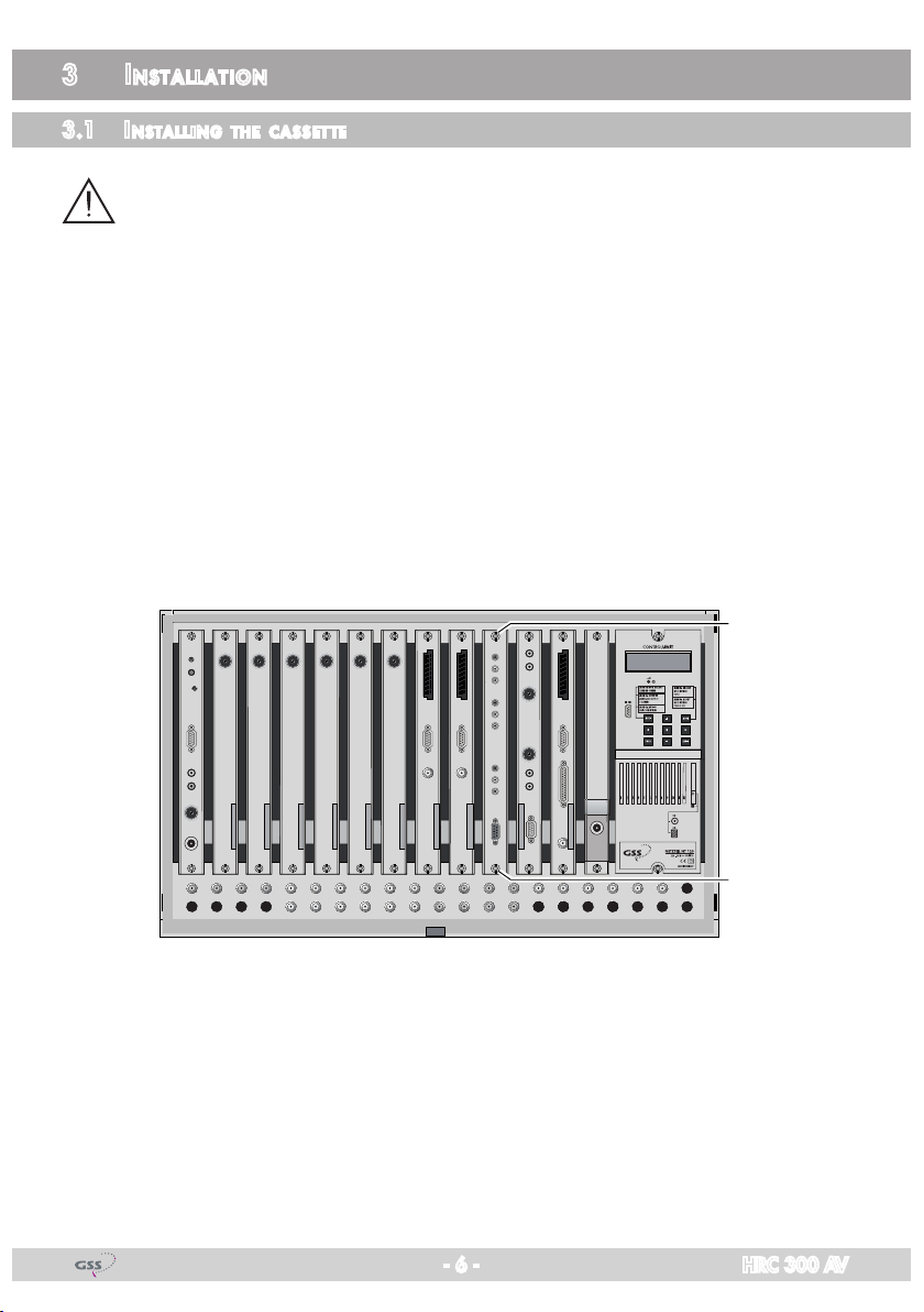
3 Installation ........................................................................................................6
3.1 Installing the cassette .......................................................................... 6
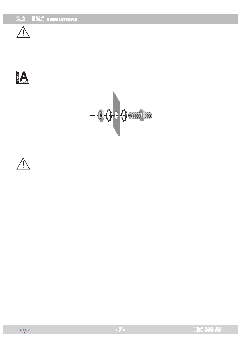
3.2 EMC regulations ................................................................................ 7
3.3 Overview of the cassette ..................................................................... 8
3.4 Connecting the cassette....................................................................... 8
4 The control unit at a glance................................................................................9
4.1 Menu items........................................................................................ 9
4.2 Control panel..................................................................................... 9
5 Programming ..................................................................................................10
5.1 Preparation...................................................................................... 10
5.2
Programming procedure.........................................................................11
5.3 Programming the cassette ................................................................. 12
Selecting the cassette........................................................................ 12
Selecting the channel strip................................................................. 13
HF output level................................................................................. 14
Switching the modulator off/on.......................................................... 14
Channel / frequency setting .............................................................. 15
TV standard of the output signal......................................................... 15
Output channel ................................................................................ 16
Fine tuning ...................................................................................... 16
Output frequency ............................................................................. 16
Audio type ...................................................................................... 17
Setting the audio output level ............................................................. 17
Saving settings................................................................................. 17
6 Final procedures.............................................................................................. 18
7 Channel and frequency tables..........................................................................19

- 3 - HRC 300 AV
1 safety regulations and notes
• Assembly,installationandservicing should be carried outbyauthorised
electricians.
• Switchofftheoperatingvoltageofthesystembeforebeginningwithassem-
bly or service work or pull out the mains plug.
• Donotperforminstallationandserviceworkduringthunderstorms.
• Installthesystemsoitwillnotbeabletovibrate…
- inadust-free,dryenvironment
- insuchamannerthatitisprotectedfrommoisture,fumes,splashingwa-
ter and dampness
- somewhere protected from direct sunlight
- not within the immediate vicinity of heat sources
- in an ambient temperature of 0 °C to +50 °C. In case of the formation of
condensation wait until the system is completely dried.
• Ensurethatthehead-endstationisadequatelyventilated.Donotcoverthe
ventilation slots.
• Bewareofshortcircuits
• Noliabilityisacceptedforanydamagecausedbyfaultyconnectionsor
inappropriate handling.
• Observetherelevantstandards,regulationsandguidelinesontheinstalla-
tion and operation of antenna systems.
• ThestandardsIEC/EN/DINEN50083resp.IEC/EN/DINEN60728must
be observed.
• For further information please read the assembly instructions for the head-
end station used.
• Test the software versions of the head-end station and the cassette and
update them if necessary. The current software versions can be found at
"www.gss.de".
Take action to prevent static discharge when working on the device!
Electronic devices should never be disposed of in the household rubbish. In
accordance with directive 2002/96/EC of the European Parliament and the
European Council from January 27, 2003 which addresses old electronic and
electrical devices, such devices must be disposed of at a designated collection
facility. At the end of its service life, please take your device to one of these
public collection facilities for proper disposal.

- 4 - HRC 300 AV
2 general information
2.1 sCope of delivery
1 HRC 300 AV cassette
1 Brief assembly instructions
2.2 meaning of the symbols used
Important note
—> General note
• Performingworks
2.3 teChniCal speCifiCations
The requirements of the following EU directives are met:
2006/95/EC,2004/108/EC
The product fulfils the guidelines and standards for CE labelling (page 20).
Unless otherwise noted all values are specified as "typical".
Input Video:
Type of signal:...................................................................... CVBS signal
Input level:.....................................................................................1 Vpp
Input impedance:............................................................................75 Ω
Frequency range: .......................................................... 20Hz…5MHz
Input Audio
Input level:............................................................................. 500 mVrms
Input impedance:.......................................................................... 10 kΩ
Frequency range: ..........................................................20Hz…15kHz
Output:
HF level:................................................................................... 95 dBμV
Channels: ............................................C02…C69includingS02…S41
Frequency range: ................................................. 42.00MHz…870.00
Standard: .........................................................................PALB/G,PALI
Output impedance:.........................................................................75 Ω

- 5 - HRC 300 AV
Connections:
Video inputs: .............................................................3 (1 per modulator)
Audio inputs: ............................................................6 (2 per modulator)
HF output: ...........................................................................1 IEC socket
Connection strip (10-pin): ..................for supply voltages and control circuits
RS 232 socket:..................................... serial interface for software update
Remote maintenance
Remotely controllable (via PSW 1000*): ..............................................yes
Remote update (via BEflash*):.............................................................yes
(* and a corresponding management unit)
2.4 desCription
The cassette is used to feed standardised audio and video signals into a ca-
ble system from completely different audio and video sources (e.g. audio and
videoreproductiondevices,testpicturegenerators,observationcamerasetc.).
The audio and video sig
nals fed in via the cinch sockets of the cassette are
modulated to adjustable carrier frequencies in the modulators and supplied to
the combiner. There they are combined and are sent to the HF output collector
of the head-end station via the HF output socket of the cassette. The common
output level can be set at the HF output collector of the head-end station.
Whenthehead-endstationisswitchedon,thetwo-lineLCdisplayshowsthe
software version of the control unit. To operate this cassette the software ver-
sion of the control unit must be "V 44" or higher. You can find the current op-
eratingsoftwareforthecontrolunitandthecassette,thesoftware"BE-Flash"
and the current assembly instructions on the website "www.gss.de".
The cassette is designed for use in head-end stations of the standard line.
displ ay of the Control unit software version
If necessary, you can activate the indication of the software version of the
control unit manually:
• Pressanytwokeysonthecontrolunitofthehead-endstationsimultaneously
untilthedisplaygoesdarkandthesoftwareversion,e.g."V 44" appears.

- 6 - HRC 300 AV
3 installation
3.1 installing the Casset te
– Ensure the head-end station is mounted so it will not be able to vibrate.
Avoid,forexample,mountingthehead-endstationontoaliftshaftorany
other wall or floor construction that vibrates in a similar way.
– Before installing or changing a cassette unplug the power cable from the
mains power socket.
• Removethefasteningscrews1of an unoccupied slot from the bracket of
the head-end station.
• Insertthecassetteinthisslotandpushitintothehousing.
• Alignthecassetteandapplyslightpressuretoconnectittotheconnections
of the board and the HF bus bar.
• Fastenthecassettewiththescrews1.
0°
1
1
KASSETTE
KASSETTE
KASSETTE
KASSETTE
KASSETTE
KASSETTE
KASSETTE
KASSETTE
KASSETTE
KASSETTE
KASSETTE
KASSETTE
HYBRID-VERSTÄRKER
MESSAUSGANG
–20 dBµV
AUSGANG
max. 106 dBµV
ACHTUNG!
Vor dem Kassettenwechsel
unbedingt
denNetzstecker ziehen.
CAUTION!
Before
changing cassettes remove
mains plug.
GrundigSATSystems

- 7 - HRC 300 AV
3.2 emC regul ations
To comply with the current EMC regulations, it is necessary to connect the lines
leading in and out of the head-end station using cable terminals.
When mounting the cassette in a head-end station which is installed in a 19"
cabinet, make sure the connections leading in and out for the 19" cabinet are
made using cable terminals.
CLASS
KLASSE
The attenuation of shielding of the connection lines for ASI and antenna must
meet the requirements for "Class A".
• Inserttherequirednumberofcableterminalsintheopeningsprovidedin
the head-end station or in the 19
"
cabinet.
Tighten the nuts of the cable terminals until the teeth on the lock washers
put un-
der
have penetrated the exterior coating and a good connection is made between
the housing
/ 19" cabinet
and cable terminals.

- 8 - HRC 300 AV
3.3 overview of the Casset te
B
A
C
L
R
V
L
R
V
L
R
V
1
AInputs of channel strip
"
A
"
RAudio input "right"
L Audioinput"left","mono"
VVideo input
B Inputs of channel strip
"
B
"
RAudio input "right"
L Audioinput"left","mono"
VVideo input
C Inputs of channel strip
"
C
"
RAudio input "right"
L Audioinput"left","mono"
VVideo input
1D-SUB socket "RS 232"
The operating software of the cassette can be updated via the 9-Pin D-SUB
socket "RS 232" using a PC or notebook and the software "BE-Flash".
You can find the current operating software on the website "www.gss.de".
3.4 ConneCting the Cassette
• ConnecttheperipheraldevicestothecinchinputsocketsV(video - yel-
low),R(audio right - red) and L(audioleft,mono-white)ofthemodula-
tors A,Band C.
•
Connect the head-end station to the mains power supply.

- 9 - HRC 300 AV
4 the Control unit at aglanCe
4.1 menu items
Program the
cassette
using the buttons on the control unit of the head-end sta-
tion. The two-line display of the control unit then shows the menus.
The parameters and functions to be set are underlined.
Use the button to select the following main menu items:
– Cassette
– Channel strip (modulator)
– HFoutputlevel,
switching the modulator on / off
– Channelorfrequencysetting,TVstandard
– Output channel / Output frequency
– Audio type / Audio level
4.2 Control panel
The key pad on the head-end station is used to scroll through the menus:
scrolls forward through the menus.
select parameters in the menus.
setvalues,initiateactions.
selects sub-menus.
scrolls backward through the menus.
saves all entries.
BE-Remote V44
please wait . . .

- 10 - HRC 300 AV
5 programming
5.1 prepar ation
• ConnectthetestreceivertotheHFoutputorthetestoutputofthehead-end
station.
• Settheoutputchannels/outputfrequenciesofthe
cassette
(page 16) and16) and) and
adjust the test receiver to the respective channel / frequency.
• Switchonthemodulatorifnecessary(page14).
• Measuretheoutputlevelsofthechannelstripsandadjustthemto
a uniform
output level (
page 17)
.

- 11 - HRC 300 AV
5.2
programming proCedure
Bx 1A 3AV
C08
Bx 1A
Level -3
MODULATOR
on
Kanalzüge ”A” / ”B” / ”C”
Channel strips ”A” / ”B” / ”C”
Bx 1A
C5-12,S3-24
TWIN-SAT
C07
Böx 4
C5-12,S3-24
TWIN-SAT
C07
Box 2
..............
..............
..............
0 … -15 dB
Box 1
V 2
3AV
– – –
Bx 1A
C08 Fine
OUTPUT
0 - 64 … + 63
▶
▶
Bx 1A
Chan
NORM
PAL B/G PAL B/G / PAL I
▶
◀/
-12 … 3 dB
M
A
▶
◀/
Chan / Freq
Bx 1A
C08
OUTPUT
Bx 1A
Stereo
AUDIO
0 dB
Ein / On
BE–Remote
please wait …
V 44
t > 10 s
B
A
Stereo /
Mono L /
Mono L+R /
Dual
on / off
▶
◀/
B

- 12 - HRC 300 AV
5.3 progr amming the Cassette
—> Pressing the button for longer than 2 seconds cancels the
programming procedure. This takes you back to the program item
"Selecting the cassette" from any menu. Any entries that have not
been saved are reset to the previous settings.
—> Entries in the menus can be saved by pressing the key. You are
taken back to the "Selecting the cassette" menu item.
—>
Pressing the
button returns to the previous menus.
• Switchonthehead-endstation.
Ein / On
BE–Remote
please wait …
V 44
t > 10 s
—> The display shows the software version (e.g. V 44)
—> The processor reads the
cassettes
‘data(approx.10seconds).
seleCting the Cassette
Bx 1A
C5-12,S3-24
TWIN-SAT
C07
Böx 4
C5-12,S3-24
TWIN-SAT
C07
Box 2
..............
..............
..............
Box 1
V 2
3AV
– – –
• Selectthecassetteyouwanttoprogram(e.g."Box 1") by repeatedly press-
ing the button if necessary.
—> The display shows e.g. the menu
"Box 1 3 AV"
:
V 2
"Box 1" stands for
slot
1
"
3AV
" type of cassette
"V 2" software version of the cassette
• Pressthe button.

- 13 - HRC 300 AV
—> The "Selecting the channel strip" – "Bx 1A" menu is activated.
seleCting the Channel strip
Bx 1A 3AV
C08
• Use to select the channel strip (modulator) "A","B" or "C" to be set.
—> The display shows e.g. the menu
Bx 1A 3AV
C08
"Bx 1" stands for
slot
1,
"A" stands for channel strip "A"
"3AV" type of cassette
"C08" channel set
—> If frequency setting is selected the frequency set is displayed instead
of the channel set
(e.g. "
196.25
").
—> Ifthechannelstrip(modulator)isswitchedoff,"
off
" is displayed instead
of the channel or the frequency set.
• Pressthe button.
—> The "HF output level" / "Switching the modulator off / on" –
"MODULATOR Level" menu is activated.

- 14 - HRC 300 AV
hf output level
In this menu you can set the HF output levels of the channel strips "A","B" and
"C" to the same values and switch on or off the modulator of the channel strip.
Bx 1A
Level -3
MODULATOR
on
•
Measure and note down the output level of channel strip "A".
• Activatemenuitem"Selecting the channel strip" using the button
and select channel strip
"B".
• Activatethe
"MODULATOR Level" menu by pressing the
button
.
•
Measure and note down the output level of channel strip "B".
• Repeatthisprocedureforchannelstrip"C".
• Selectthechannelstrips
with the higher HF
output levels one after the other
and by pressi
ng adjust the higher output levels of the channel strips to
the output level of the channel strip with the lowest output level ("0
" to "
–15"
dB).
• Activatemenuitem"Selecting the channel strip" using the button if
necessary and call up
the channel strip
to be programmed.
switChing the modul ator off/on
Bx 1A
Level -3
MODULATOR
on
•
Place the cursor under "on" or "off" using the buttons.
• Press to switch the modulator of the channel strip "off" or "on".
—> In position "off" the "Level" menu item is inactive.

- 15 - HRC 300 AV
• Pressthe button.
—> The "Channel / frequency setting" / "TV standard of the output
signal" – "NORM" menu is activated.
Channel / frequenCy set ting
Inthismenu,youcanselectthechannelorfrequencysettingfortheadjustment
oftheHFoutput.ThechannelsettingcoverstherangeofchannelsC02…
C69includingchannelsS02…S41,thefrequencysettingcoverstherange
from 42.00 MHz to 870..00 MHz. Additionally the TV standard of the output
signal can be set.
Bx 1A
Chan
NORM
PAL B/G
• Press to select channel setting "Chan" or frequency setting "Freq".
tv standard of the output signal
Bx 1A
Chan
NORM
PAL B/G
• PlacethecursorundertheTVstandarddisplayedusingthe
buttons.
• Press to select the TV standard of the output signal ("PAL B/G" /
"PAL I").
• Pressthe
button
.
—> The "Setting the output channel" or "Setting the output frequency" –
"OUTPUT" menu is activated.

- 16 - HRC 300 AV
output Channel
Bx 1A
C08 Fine
OUTPUT
0
▶
▶
Bx 1A
C08
OUTPUT
• Use to set the output channel of the modulator.
fine tuning
Adjust the fine tuning (frequency offset) only in individual cases
which give you
reasontodoso(e.g.moiré,
interferences),sinceallTVsetsconnectedtothe
cable system have to be fine tuned after making changes.
• Pressthe
buton.
Bx 1A
C08 Fine
OUTPUT
0
—> "FINE 0" additionally appears on the display.
• Use to set the fine tuning.
• Press
to return to the main menu.
output frequenCy
Bx 1A
196,25 MHz
OUTPUT
• Usethe
buttons to place the cursor under the digit of the frequency
displayedtobeset,thenuse to set the output frequency wished.
• Pressthe button.
—> The "Audio type" / "Audio output level" – "AUDIO" menu is acti-
vated.

- 17 - HRC 300 AV
audio type
In this menu you can set the audio type in which the modulator is to modulate
the audio signals. If a mono audio signal (white Cinch socket) is fed in into a
channelstrip,programtherespectivechannelstripto"Mono L". Additionally
you can adjust various audio output levels of the signal sources.
Bx 1A
Stereo
AUDIO
0 dB
• Use to set the audio type ("Stereo","Mono L","Mono L+R","Dual").
setting the audio output level
Bx 1A
Stereo
AUDIO
0 dB
• Feedinanexternalaudiosignal(referto"Technicalspecifications").
• Use to set the audio output level.
saving settings
• Pressthe button.
—>
The settings are saved.
—> You return to the "Selecting the cassette" menu (page 12).
—> By pressing the button,youwillbereturnedtothemenu
item "Selecting the channel strip" without
saving the programmed
data
(page 13).

- 18 - HRC 300 AV
6 final proCedures
After installing the head-end station, upgrading accessories or installing cas-
settes it is necessary to tighten all cable connections, cable terminals and cover
screws in order to maintain compliance with current EMC regulations securely.
• Securelytightenthecable connectionsusinganappropriate open-ended
spanner.
• Measuretheoutputlevelsoftheothercassettesandtunethemtoauniform
output level using the appropriate level controls or software dependent on
the head-end station used. Please regard the assembly instructions of the
respective head-end station.
—>
In order to prevent interference within the head-end station and the
cablesystem,theoutputlevelsofthedigitalcassettesmustbeset
lower by 8dB compared to analogue cassettes.
• Mountthefrontcover(s.assemblyinstructionsofthehead-endstation).

- 19 - HRC 300 AV
7 Channel and frequenCy tables
CCIR – Band I/III (Frequency raster 7 MHz)
CCIR – Hyperband (Frequency raster 8 MHz)
CCIR – Band IV/V (Frequency raster 8 MHz)
Kanal
Channel
Bildträgerfrequenz
Picture carrier frequency
[MHz
]
C 2 48.25
C 3 55.25
C 4 62.25
S 2 112.25
S 3 119.25
S 4 126.25
Kanal
Channel
Bildträgerfrequenz
Picture carrier frequency
[MHz
]
S 5 133.25
S 6 140.25
S 7 147.25
S 8 154.25
S 9 161.25
S 10 168.25
Kanal
Channel
Bildträgerfrequenz
Picture carrier frequency
[MHz
]
C 5 175.25
C 6 182.25
C 7 189.25
C 8 196.25
C 9 203.25
C 10 210.25
Kanal
Channel
Bildträgerfrequenz
Picture carrier frequency
[MHz
]
C 11 217.25
C 12 224.25
S 11 231.25
S 12 238.25
S 13 245.25
S 14 252.25
Kanal
Channel
Bildträgerfrequenz
Picture carrier frequency
[MHz
]
S 15 259.25
S 16 266.25
S 17 273.25
S 18 280.25
S 19 287.25
S 20 294.25
Kanal
Channel
Bildträgerfrequenz
Picture carrier frequency
[MHz
]
S 21 303.25
S 22 311.25
S 23 319.25
S 24 327.25
S 25 335.25
S 26 343.25
Kanal
Channel
Bildträgerfrequenz
Picture carrier frequency
[MHz
]
S 27 351.25
S 28 359.25
S 29 367.25
S 30 375.25
S 31 383.25
S 32 391.25
Kanal
Channel
Bildträgerfrequenz
Picture carrier frequency
[MHz
]
S 33 399.25
S 34 407.25
S 35 415.25
S 36 423.25
S 37 431.25
S 38 439.25
Kanal
Channel
Bildträgerfrequenz
Picture carrier frequency
[MHz
]
S 39 447.25
S 40 455.25
S 41 463.25
C 21 471.25
C 22 479.25
C 23 487.25
C 24 495.25
C 25 503.25
C 26 511.25
C 27 519.25
C 28 527.25
C 29 535.25
C 30 543.25
C 31 551.25
C 32 559.25
C 33 567.25
C 34 575.25
C 35 583.25
C 36 591.25
C 37 599.25
C 38 607.25
C 39 615.25
C 40 623.25
C 41 631.25
C 42 639.25
C 43 647.25
C 44 655.25
C 45 663.25
C 46 671.25
C 47 679.25
C 48 687.25
C 49 695.25
C 50 703.25
C 51 711.25
C 52 719.25
C 53 727.25
C 54 735.25
C 55 743.25
C 56 751.25
C 57 759.25
C 58 767.25
C 59 775.25
C 60 783.25
C 61 791.25
C 62 799.25
C 63 807.25
C 64 815.25
C 65 823.25
C 66 831.25
C 67 839.25
C 68 847.25
C 69 855.25

- 20 - HRC 300 AV
Declaration of CE conformity
Other manuals for HRC 300 AV
1
Table of contents
Other GSS Media Converter manuals

GSS
GSS SDA 521 User manual

GSS
GSS PHIS 1000 S User manual

GSS
GSS HDE 200 User manual

GSS
GSS PTDT 9200 User manual

GSS
GSS Professional PADE 7006 User manual

GSS
GSS PHDQ 8008 TSR User manual

GSS
GSS PTDQ 1000 ASI LAN User manual

GSS
GSS PHDQ 8008 TSR User manual

GSS
GSS SOQD 104 User manual

GSS
GSS STI 1916 CT User manual

GSS
GSS STC 100 User manual

GSS
GSS HDTV 1000 SPTS User manual

GSS
GSS GSS.mux SMCIP 401 User manual

GSS
GSS PTIS 1000 User manual

GSS
GSS PTIM 1000 User manual

GSS
GSS HMPT 1000 T User manual

GSS
GSS HDE 166 User manual

GSS
GSS PEDQ 3005 QMX User manual

GSS
GSS PTDQ 1000 ASI LAN User manual

GSS
GSS HRC 300 AV User manual