Guardian A5-6000 User manual

USER MANUAL
GUARDIAN
A5-6000 Dispensing System
T
H
I
S
E
Q
U
I
P
M
E
N
T
I
S
P
R
O
T
E
C
T
E
D
B
Y
CHINESE
PATENT
ZL 200630130159.1
T
H
I
S
E
Q
U
I
P
M
E
N
T
I
S
P
R
O
T
E
C
T
E
D
B
Y
U.S.A.
PATENT
D546,840
Important Safety Instructions
Read all warnings and instructions in
this manual. Save these instructions.
)RUXVHZLWKQRQÀDPPDEOHIRDPDQGSRO\XUHD
1RWIRUXVHLQH[SORVLYHDWPRVSKHUHV
0D[LPXPÀXLGZRUNLQJSUHVVXUH
SVL03DEDU

Table Of Contents
Section 1 Installation
Warnings ............................................................................................................................................................ 1
Introduction ........................................................................................................................................................ 5
Standard Equipment .......................................................................................................................................... 6
Technical Data ......................................................................................................................... 7
Equipment Assembly .......................................................................................................................................... 8
Section 2 Operation
Start-up Instructions ........................................................................................................................................... 14
Shut–down Instructions ...................................................................................................................................... 18
Section 3 General Information
Assembly Drawings ............................................................................................................................................. 22
Sub Assembly Drawings ...................................................................................................................................... 29
Maintenance ........................................................................................................................................................ 36
Troubleshooting ................................................................................................................................................... 37
Options ................................................................................................................................................................ 40
Section 4 Warranty and Reference Information
Limited Warranty Policy ............................................................................................................ 41
Technical Assistance ................................................................................................................ 42
For Your Reference ............................................................................................. INSIDE BACK COVER

1
Warnings
The following warnings are for the setup, use, grounding, maintenance, and repair of this equipment. The exclamation
SRLQWV\PERODOHUWV\RXWRDJHQHUDOZDUQLQJDQGWKHKD]DUGV\PEROUHIHUVWRSURFHGXUHVSHFL¿FULVN5HIHUEDFNWRWKHVH
ZDUQLQJV$GGLWLRQDOSURGXFWVSHFL¿FZDUQLQJVPD\EHIRXQGWKURXJKRXWWKHERG\RIWKLVPDQXDOZKHUHDSSOLFDEOH
WARNING
ELECTRIC SHOCK HAZARD
,PSURSHUJURXQGLQJVHWXSRUXVDJHRIWKHV\VWHPFDQFDXVHHOHFWULFVKRFN
Turn off and disconnect power cord before servicing equipment. Use only grounded electrical outlets. Use only 3-wire extension cords. Ensure ground prongs are intact on sprayer and extension cords. Do not expose to rain. Store indoors.
TOXIC FLUID OR FUMES HAZARD
7R[LFÀXLGVRUIXPHVFDQFDXVHVHULRXVLQMXU\RUGHDWKLIVSODVKHGLQWKHH\HVRURQVNLQLQKDOHGRU
swallowed.
5HDG06'6¶VWRNQRZWKHVSHFL¿FKD]DUGVRIWKHÀXLGV\RXDUHXVLQJ
6WRUHKD]DUGRXVÀXLGLQDSSURYHGFRQWDLQHUVDQGGLVSRVHRILWDFFRUGLQJWRDSSOLFDEOHJXLGH- lines.
Always wear impervious gloves when spraying or cleaning equipment.
PERSONAL PROTECTIVE EQUIPMENT
You must wear appropriate protective equipment when operating, servicing, or when in the operating
DUHDRIWKHHTXLSPHQWWRKHOSSURWHFW\RXIURPVHULRXVLQMXU\LQFOXGLQJH\HLQMXU\LQKDODWLRQRIWR[LF
fumes, burns, and hearing loss. This equipment includes but is not limited to:
Protective eyewear
&ORWKLQJDQGUHVSLUDWRUDVUHFRPPHQGHGE\WKHÀXLGDQGVROYHQWPDQXIDFWXUHU Gloves Hearing protection
SKIN INJECTION HAZARD
+LJKSUHVVXUHÀXLGIURPJXQKRVHOHDNVRUUXSWXUHGFRPSRQHQWVZLOOSLHUFHVNLQ7KLVPD\ORRNOLNH
MXVWDFXWEXWLWLVDVHULRXVLQMXU\WKDWFDQUHVXOWLQDPSXWDWLRQGet immediate surgical treatment.
Do not point gun at anyone or at any part of the body. Do not put your hand over the spray tip.
'RQRWVWRSRUGHÀHFWOHDNVZLWK\RXUKDQGERG\JORYHRUUDJ Close material shutoff valves, and then shut off or disconnect air supply when not spraying. Follow Pressure Relief Procedure in this manual, when you stop spraying and before cleaning,
FKHFNLQJRUVHUYLFLQJHTXLSPHQW

2
WARNING
FIRE AND EXPLOSION HAZARD
)ODPPDEOHIXPHVVXFKDVVROYHQWDQGSDLQWIXPHVLQZRUNDUHDFDQLJQLWHRUH[SORGH7RKHOSSUH-
YHQW¿UHDQGH[SORVLRQ
Use equipment only in well ventilated area. Eliminate all ignition sources; such as pilot lights, cigarettes, portable electric lamps, and plastic drop cloths (potential static arc).
.HHSZRUNDUHDIUHHRIGHEULVLQFOXGLQJVROYHQWUDJVDQGJDVROLQH
'RQRWSOXJRUXQSOXJSRZHUFRUGVRUWXUQSRZHURUOLJKWVZLWFKHVRQRURIIZKHQÀDPPDEOH fumes are present.
*URXQGDOOHTXLSPHQWLQWKHZRUNDUHD Use only grounded hoses.
+ROGJXQ¿UPO\WRVLGHRIJURXQGHGSDLOZKHQWULJJHULQJLQWRSDLO
,IWKHUHLVVWDWLFVSDUNLQJRU\RXIHHODVKRFN stop operation immediately. Do not use equip-
ment until you identify and correct the problem.
.HHSDZRUNLQJ¿UHH[WLQJXLVKHULQWKHZRUNDUHD
PRESSURIZED ALUMINUM PARTS HAZARD
Do not use 1,1,1-trichloroethane, methylene chloride, other halogenated hydrocarbon
VROYHQWVRUÀXLGVFRQWDLQLQJVXFKVROYHQWVLQSUHVVXUL]HGDOXPLQXPHTXLSPHQW6XFK
use can cause serious chemical reaction and equipment rupture, and result in death,
VHULRXVLQMXU\DQGSURSHUW\GDPDJH
EQUIPMENT MISUSE HAZARD
0LVXVHFDQFDXVHGHDWKRUVHULRXVLQMXU\
'RQRWRSHUDWHWKHXQLWZKHQIDWLJXHGRUXQGHUWKHLQÀXHQFHRIGUXJVRUDOFRKRO
'RQRWH[FHHGWKHPD[LPXPZRUNLQJSUHVVXUHRUWHPSHUDWXUHUDWLQJRIWKHORZHVWUDWHGV\VWHP component. See Technical Data in all equipment manuals.
8VHÀXLGVDQGVROYHQWVWKDWDUHFRPSDWLEOHZLWKHTXLSPHQWZHWWHGSDUWV6HH Technical Data in
DOOHTXLSPHQWPDQXDOV5HDGÀXLGDQGVROYHQWPDQXIDFWXUHU¶VZDUQLQJV)RUFRPSOHWHLQIRUPD-
tion about your material, request MSDS forms from distributor or retailer.
&KHFNHTXLSPHQWGDLO\5HSDLURUUHSODFHZRUQRUGDPDJHGSDUWVLPPHGLDWHO\ZLWKJHQXLQH manufacturer’s replacement parts only.
Do not alter or modify equipment. Use equipment only for its intended purpose. Call your distributor for information.
5RXWHKRVHVDQGFDEOHVDZD\IURPWUDI¿FDUHDVVKDUSHGJHVPRYLQJSDUWVDQGKRWVXUIDFHV
'RQRWNLQNRURYHUEHQGKRVHVRUXVHKRVHVWRSXOOHTXLSPHQW
.HHSFKLOGUHQDQGDQLPDOVDZD\IURPZRUNDUHD Comply with all applicable safety regulations.
MOVING PARTS HAZARD
0RYLQJSDUWVFDQSLQFKRUDPSXWDWH¿QJHUVDQGRWKHUERG\SDUWV
Keep clear of moving parts. Do not operate equipment with protective guards or covers removed.
3UHVVXUL]HGHTXLSPHQWFDQVWDUWZLWKRXWZDUQLQJ%HIRUHFKHFNLQJPRYLQJRUVHUYLFLQJHTXLS- ment, follow the Pressure Relief Procedure in this manual. Disconnect power or air supply.
BURN HAZARD
(TXLSPHQWVXUIDFHVDQGÀXLGWKDW¶VKHDWHGFDQEHFRPHYHU\KRWGXULQJRSHUDWLRQ7RDYRLG
VHYHUHEXUQVGRQRWWRXFKKRWÀXLGRUHTXLSPHQW:DLWXQWLOHTXLSPHQWÀXLGKDVFRROHGFRPSOHWHO\
Warnings

3
Isocyanate Hazard
Spraying materials containing isocyanates creates
potentially harmful mists, vapors, and atomized
particulates.
Read material manufacturer’s warnings and
PDWHULDO06'6WRNQRZVSHFL¿FKD]DUGVDQG
precautions related to isocyanates.
Prevent inhalation of isocyanate mists, vapors, and
DWRPL]HGSDUWLFXODWHVE\SURYLGLQJVXI¿FLHQWYHQWLOD-
WLRQLQWKHZRUNDUHD,IVXI¿FLHQWYHQWLODWLRQLVQRW
available, a supplied-air respirator is required for
HYHU\RQHLQWKHZRUNDUHD
To prevent contact with isocyanates, appropriate
personal protective equipment, including chemically
impermeable gloves, boots, aprons, and goggles, is
DOVRUHTXLUHGIRUHYHU\RQHLQWKHZRUNDUHD
Moisture Sensitivity of
Isocyanates
Isocyanates (ISO) are catalysts used in two component
foam and polyurea coatings. ISO will react with moisture
(such as humidity) to form small, hard, abrasive crystals,
ZKLFKEHFRPHVXVSHQGHGLQWKHÀXLG(YHQWXDOO\D¿OPZLOO
form on the surface and the ISO will begin to gel, increas-
ing in viscosity. If used, this partially cured ISO will reduce
performance and the life of all wetted parts.
7KHDPRXQWRI¿OPIRUPDWLRQDQGUDWHRIFU\VWDO-
lization varies depending on the blend of ISO,
the humidity, and the temperature.
To prevent exposing ISO to moisture:
Always use a sealed container with a desiccant dryer in the vent, or a nitrogen atmosphere. Never store ISO
in an open container.
.HHSWKH,62OXEHSXPSUHVHUYRLU¿OOHGZLWK*UDFR Throat Seal Liquid (TSL), Part 206995. The lubricant
creates a barrier between the ISO and the atmosphere.
8VHPRLVWXUHSURRIKRVHVVSHFL¿FDOO\GHVLJQHGIRU ISO, such as those supplied with your system.
Never use reclaimed solvents, which may contain
PRLVWXUH$OZD\VNHHSVROYHQWFRQWDLQHUVFORVHGZKHQ
not in use.
Never use solvent on one side if it has been contami- nated from the other side.
$OZD\VSDUNSXPSVZKHQ\RXVKXWGRZQ
Always lubricate threaded parts with Part 217374 ISO pump oil or grease when reassembling.
Warnings

4
Material Self-ignition
Some materials may become self-igniting if applied to
WKLFNO\ 5HDG PDWHULDO PDQXIDFWXUHU¶V ZDUQLQJV DQG
material MSDS.
Keep Components A and B
Separate
CAUTION
To prevent cross-contamination of the equipment’s wet-
ted parts, never interchange component A (isocyanate)
and component B (resin) parts. The gun is shipped with
WKH$VLGHRQWKHOHIW7KHÀXLGPDQLIROGÀXLGKRXV-
LQJVLGHVHDODVVHPEO\FKHFNYDOYHFDUWULGJHDQGPL[
FKDPEHUDUHPDUNHGRQWKH$VLGH
Foam Resins with 245 fa
Blowing Agents
New foam blowing agents will froth at temperatures above
90°F (33 °C) when not under pressure, especially if agitat-
ed. To reduce frothing, minimize preheating in a circulation
system.
Changing Materials
:KHQFKDQJLQJPDWHULDOVÀXVKWKHHTXLSPHQWPXO- tiple times to ensure it is thoroughly clean.
$OZD\VFOHDQWKHÀXLGLQOHWVWUDLQHUVDIWHUÀXVKLQJ
&KHFNZLWK\RXUPDWHULDOPDQXIDFWXUHUIRUFKHPLFDO compatibility.
Most materials use ISO on the A side, but some use ISO on the B side.
Epoxies often have amines on the B (hardener) side. Polyureas often have amines on the B (resin) side.
Warnings

Section 1 - Installation: Introduction
5
Introduction
Before operating, maintaining or servicing any
GlasCraft system, read and understand all of the
technical and safety literature provided with GlasCraft
products. If you do not have the proper or related
manuals and safety literature for your GlasCraft system,
contact your GlasCraft distributor.
In this GlasCraft technical and safety publication, the
following advisories will be provided where appropriate:
Information about the procedure in progress.
Is imperative information about equipment protection.
Indicates a hazardous situation that can
result in minor or moderate injury.
Indicates a hazardous situation that can
result in death or serious injury.
Indicates a hazardous situation that can
result in electrical shock or serious injury.
The information in this document is intended only to
LQGLFDWHWKHFRPSRQHQWVDQGWKHLUQRUPDOZRUNLQJ
relationship typical use. Each assembly should be
directed by a GlasCraft distributor or made from the
GlasCraft Assembly instructions provided.
This manual provides information for the assembly, opera-
tion, maintenance and service of this GlasCraft product as
XVHGLQDW\SLFDOFRQ¿JXUDWLRQ:KLOHLWOLVWVVWDQGDUGVSHFL¿
cations and procedures, some deviations may be found.
In order to provide our users with the most up-to-date
WHFKQRORJ\SRVVLEOHZHDUHFRQVWDQWO\VHHNLQJWRLPSURYH
products. If a technological change occurs after a prod-
XFWLVRQWKHPDUNHWZHZLOOLPSOHPHQWWKDWWHFKQRORJ\LQ
IXWXUHSURGXFWLRQDQGLISUDFWLFDOPDNHLWDYDLODEOHWRFXU-
UHQWXVHUVDVDUHWUR¿WXSGDWHRUVXSSOHPHQW,I\RX¿QG
a discrepancy between your unit and the available docu-
mentation, contact your GlasCraft distributor to resolve the
difference.
Careful study and continued use of this manual will pro-
vide a better understanding of the equipment and process,
UHVXOWLQJLQPRUHHI¿FLHQWRSHUDWLRQORQJHUWURXEOHIUHH
service and faster, easier troubleshooting.
WARNING
CAUTION
ELECTRICAL SHOCK HAZARD

Section 1 - Installation: Standard Equipment
6
Model - A5-6000
* Purchase separately
Recommended Repair Parts
Part Description
GC1748 HEATER REPAIR KIT
Related Manuals
Part Description
312766 T1 2:1 RATIO TRANSFER PUMP INSTRUCTIONS-PARTS
309572 HEATED HOSE INSTRUCTIONS-PARTS
313277 MATERIAL PUMPS INSTRUCTIONS
Part Description
GC1750
GC1752
GC1753
A5-6000 UNIT; 220V, 1PH, F
A5-6000 UNIT; 220V, 3PH, F
A5-6000 UNIT; 380V, 3PH, C
GCP2R2* PROBLER P2 GUN
246075* POWER LOCK HEATED HOSE
246050* WHIP HOSE ASSEMBLY
313268 USER MANUAL
206995 FLUID, TSL, 1 QT. BOTTLE
GC0174 TRANSFER KIT; A5 AND A6 UNITS (DOES NOT INCLUDE TRANFER PUMPS

7
Material Ratio: 1:1 (Fixed)
Material Viscosity: 200- 2000 Centipoise (Cps) @ AMBIENT
Output: Pumps Rated:
.042 Gallons Per Cycle
.159 Liters Per Cycle
Operating Temperatures: 32º F ( 0º C ) - 180º (82 º C )
0D[LPXPDLUZRUNLQJSUHVVXUH SVL03DEDU
0D[LPXPÀXLGZRUNLQJSUHVVXUH 5$7,2SVL03DEDU
(OHFWULFDO5HTXLUHPHQWV $#9$&K]6LQJOH3KDVH
(cable: 6 AWG, 2 wire + GND)
$#9$&K]7KUHH3KDVH
(cable: 8 AWG, 3 wire + GND)
20 A @ 380 VAC, 50 hz. Three Phase
(cable: 12 AWG, 4 wire + GND)
Compressed Air Requirements: Base Unit:
1.0 GAL PER MINUTE – 17 CFM @ 100 psi
1.5 GAL PER MINUTE – 24 CFM @ 100 psi
2.0 GAL PER MINUTE – 33 CFM @ 100 psi
NOTE:$VRXWSXWLVLQFUHDVHGDFKLHYHGZFKDPEHU
size on gun or spray tip), pressure drop will be greater.
Heating capability will also drop.
Heaters: 6000 WATT HEATER
Maximum Hose Length: 310 ft. (94.5 m)
(DFK6HFWLRQIW[LQ,'
6KLSSLQJ:HLJKW OEVNJ
Overall Dimensions:
Section 1 - Installation: Technical Data

8
Section 1 - Installation: Equipment Assembly
Guardian Line Installation Guide
GlasCraft Systems are factory assembled. If any
questions arise concerning air or electrical
connections, please refer to illustrations located in
the forward portion of this User Manual or contact
your GlasCraft distributor.
1. Locate Guardian.
a. Locate Guardian on a level surface.
b. Do not expose Guardian to rain.
Bolt Guardian to orginanl shipping pallet before
lifting.
c.8VHWKHZKHHOVWRPRYH*XDUGLDQWRD¿[HG
location, or bolt to shipping pallet and move with
IRUNOLIW
d. 7RPRXQWRQDWUXFNEHGRUWUDLOHUDQGEROW
GLUHFWO\WRWUXFNRUWUDLOHUEHG
2. Advanced preparation
a. Before beginning any installation, ensure that the
applicator has the desired power supply available,
LH9VLQJOHSKDVH9WKUHHSKDVH
within 10 ft. of were the machine is to be placed.
If the machine needs to be further that 10 ft. from
the power supply, additional lengths of properly
sized electrical cable will be required.
Never use a smaller gauge size than supplied
by the factory!
b. Depending on the electrical setup, it may be
necessary to install an appropriate plug on the end
of the cable. GlasCraft will not supply this plug, as
we are unaware of which style will be needed.
c.&RQVXOWWKHGDWDVKHHWIRUWKHVSHFL¿FXQLWEHLQJ
LQVWDOOHGWRGHWHUPLQHWKHSURSHUEUHDNHUVL]H
needed.
d. You will need to run an air line to the area where
the machine will be placed. consult the data
VKHHWWKHVSHFL¿FXQLWEHLQJLQVWDOOHGWRGHWHUPLQH
how much clean, dry air will be needed to supply
the machine. If the air line is under 25 ft. use a
PLQLPXPRILQ,'SLSHRUKRVH,IWKHDLUOLQH
is longerWKDQIWXVHDPLQLPXPRILQ
pipe or hose. Anything smaller than these
diameters will severly affect the machine’s
performance!
'RQRWXVHDQ\TXLFNGLVFRQQHFW¿WWLQJVRQ
the main air line going to the machine!
Check your air-compressor to make sure it is
capable of supplying the maximum amount of air
that the machine requires. All GlasCraft equipment
is rated at 25 CFM (cubic foot per minute) 708
liters @ 90-100 psi (0.62-0.7 MPa, 6.3-7.7 BAR)
do not exceed 125 PSI (0.86 MPa, 8.6 bar).
2. Move material drums to the area that the equipment will
be placed, ensuring that they are not sitting directly on
WKHÀRRU6LPSO\SODFHWKHGUXPVRQWRSRIDSDOOHWRU
similar device, so the drum bottoms will not be in
contact with any cold surfaces.
3. Open all boxes that came with the machine and verify
that all items are accounted for.
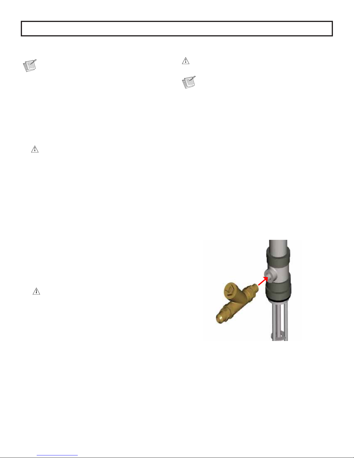
4. ,QVWDOO<¿OWHUVSURYLGHGLQWUDQVIHUNLW*&LQWR
outlets of both transfer pumps (purchase separately.
Be sure to use PTFE tape on the threads.

5. ,QVWDOODPDOHTXLFNGLVFRQQHFW¿WWLQJWRDLULQOHWRI
both pumps. Besure to use PTFE tape on the threads.
6. Remove the 2 inch bung caps on both the A and B
side drums. Install the transfer pump
FROODUVEXQJDGDSWHUVLQWRWKHEXQJKROHVPDNLQJ
sure to lubricate the threads with vaseline or
grease, thus enabling easy removal when needed.
7.0DNHVXUHWKDWWKHSODVWLFFDSVKDYHEHHQUHPRYHG
from the bottom of the pumps and then slide the
transfer pumps into the collars. Tighten the collars,
securing the transfer pumps in place.
/RRVHQWKHLQYHQWSOXJVRQERWKGUXPV
allowing for ventilation. If using a desiccant dryer on
the A side, install it now.
8. Remove the metal caps from the material pumps.
Section 1 - Installation: Equipment Assembly
9

Section 1 - Installation: Equipment Assembly
10
9. Connect one end of each material hose (provided in
WUDQVIHUNLW*&WRWKHLQOHW
¿WWLQJVORFDWHGRQWKHEDFNRIWKHPDFKLQHIt is
highly recommended that you label the (POLY)
hose with BLUE tape and the (ISO) hose with RED
tape to ensure that you don’t put the wrong transfer
pump in the opposite material drum.
10. Connect the other end of the material hoses to
the correct transfer pumps. Ensure that they
are not reversed and tighten securely.
POLY
Material
Drum

Section 1 - Installation: Equipment Assembly
11
POLY
Material
Inlet Fitting
ISO
Material
Inlet Fitting
11. a. ,QVWDOOWKHIHPDOHTXLFNGLVFRQQHFW¿WWLQJVRQWRWKH
óLQDLUOLQHVWKDWFDPHLQWKHWUDQVIHUNLWBe sure
to use PTFE tape on the threads.
b. $WWDFKWKHTXLFNGLVFRQQHFW¿WWLQJVWRWKHPDOH
receivers on the transfer pumps.
12. Attach the other end of the airlines to the far right
regulator on the machines air manifold.
ISO
Material
Drum

Section 1 - Installation: Equipment Assembly
12
13.,IWKHRSWLRQDOVFXIIMDFNHWLVEHLQJ
used (highly recommended, sold separately)
install it over each individual section of hose
before proceeding any further. Securely tape both
HQGVRIVFXIIMDFNHWWRWKHKRVHDVVHPEO\
14.Locate the thermal couple wire protruding from the
%VLGH¿WWLQJRQWKHIURQWRIWKHPDFKLQH8QFRLO
the wire and lay it out straight.
Main power from power source should be disconnected
or turned off to console before making hose
connections.
15. Feed the the thermal couple wire into the B side
portion of the hose and pull the rest of the hose up
until you can connect the hose to the front of the
machine. Tighten the hose securely, being careful
not to twist the hose in an “un-natural” bend.
Refer to the last page in this installation guide for
instructions on how to secure hoses properly.
16. &RQQHFWWKHLQDLUOLQHRQWKHKRVHDVVHPEO\WR
the air line whip hose on the front of the machine.
17. Connect electrical wires using electrical connectors
installed on unit.
Elect
See Heated Hose manual 309572 for detailed
instructions of connecting heated hoses.
Heated hose length, including whip hose, must
be 60 ft. (18.3) minimum.
18. Add extra hose lengths if necessary.
Ferrules
Electrical Connector

13
19. Connect hose assembly and the gun as
VKRZQ7KH¿WWLQJVRQWKHKRVHDVVHPEO\
are sized differently and will attach only one way.
20.3UHVVXUHFKHFNKRVH6HH+HDWHG+RVHPDQXDO
3UHVVXUHFKHFNIRUOHDNV,I\RXGRQRW
¿QGDQ\OHDNVZUDSKRVHDQGHOHFWULFDO
connections to prevent damage.
When main power to system console is on, the white
and black wires in the console are always live!
Disconnect or turn off main power source before
opening console to make any repairs or before making
any electrical repair of any type to the system.
If you do not understand the electrical hook-up
described above, consult your local GlasCraft distributor
25DTXDOL¿HGHOHFWULFLDQ
Electrical connections must be checked on a
periodic basis.
YROWVLQJOHSKDVH
//*5281'
YROWWKUHHSKDVH
///*5281'
YROWWKUHHSKDVH
/EODFN
/EURZQ
/EODFN
/EOXH
*5281'JUHHQ
21. If more than 50 ft. of hose is used, the transformer tap
setting will need to be set for proper hose length. The
VWLFNHURQWKHIURQWFRYHUZLOOVD\ZKLFKWDSWRPRYH
the wire to. DO NOT MOVE THE COMMON LEG!
Section 1 - Installation: Equipment Assembly

14
Never leave machine unattended while system power
is on or system is running.
6\VWHPUXQQLQJLVGH¿QHGDVSUHKHDWF\FOHRIWKHKRVH
heat, primary heaters, or any pump operation.
Machine operators must be familiar with the
component functions and operation of the machine.
Pre-Operation Check List
A. &KHFNWKDWDOO¿WWLQJVDUHVHFXUHO\WLJKW
B. &KHFNHOHFWULFDOKRRNXSTXDOL¿HGHOHFWULFLDQ
recommended).
C. Main power switch on control box should be
switched to OFF position.
D.$LUUHJXODWRUWXUQHGFRXQWHUFORFNZLVHWROFF
position.
E. Hose control and primary heater control to OFF
position.
Do not place any part of the body in the path of the
material spray.
Do not point the gun at or near other personnel.
'RQRWORRNLQWRWKH0L[LQJ&KDPEHURUL¿FHDWDQ\WLPH
Because of the hazardous materials used in this
equipment, it is recommended that the operator use
an air mask, goggles, protective clothing, and other
safety equipment as prescribed by current regulations,
recommendations of the chemical suppliers, and the
laws in the area where the equipment is being used.
Initial Start-Up Procedure
With all material and air lines connected and power
cable attached, the system is now ready for start-up.
Filling The System
1. $GMXVW$LU5HJXODWRUWR36,WR¿OOV\VWHP$LU
0RWRUZLOOF\FOHVORZO\WR¿OO3XPSV+HDWHUVDQG
Hoses and stop.
2. 5HPRYH,6232/<VLGHEORFNVIURPJXQ
PROBLER P2
MAKE SURE VALVES ARE OFF
Section 2 - Operation: Start-Up Instructions

15
3. Place separate clean containers under each indi-
YLGXDOVLGHEORFNSlowly open material valves
EODFNDUURZIRUZDUGRQHDFKVLGHEORFNWRDOORZ
WUDSSHGDLUWRHVFDSHWKHKRVHDQGPDWHULDOWRÀRZ
into the containers until all air is purged from the
material system.
Remember to dispense one to two gallons of
material to clear the system of grease and
plasticizer that was used during factory testing.
4. Close manual material valves. Material pressure
gauges should now register approximately equal
pressure. If one side registers considerably more
pressure than the other side, go to the high pres-
sure side and bleed off some pressure by slightly
opening the manual material valve on the side
EORFNRYHUWKHFRQWDLQHU%OHHGSUHVVXUHXQWLOERWK
sides are approximately the same pressure.
5. Dispose of waste material properly and in accor-
dance with chemical suppliers instructions and
local, state and federal regulations.
Before re-assembling side blocks, lubrication can be
applied by dabbing a white lithium grease into holes
inside of gun front housing and wiping grease over
side block seals. Grease will purge itself when the air
valve is turned on at gun and gun is triggered.
6.&OHDQDQGOXEULFDWHVLGHEORFNVDQGVHDOVWKRURXJKO\
DQGUHDVVHPEOHRQJXQ0DNHFHUWDLQWKDWWKHVLGH
EORFNVFUHZVDUHWLJKWHQHGVHFXUHO\
7. Refer to material manufacturers operating instructions
for proper preparation of material, i.e, mixers, etc.
8. Leave air regulator at 20 PSI
9. Turn main power Switch to ON position.
10. Turn on Hose Control:
a. Push in the green power button.
b. Press up or down arrow buttons on the controller
until desired temperature setting is achieved.
Section 2 - Operation: Start-Up Instructions

16
11. Turn on the ISO & POLY Heater control:
a. Push in green power button.
b. Press up or down arrow buttons on the
controller until desired temperature setting is
achieved.
6WUDLJKWHQKRVHRXWÀDWWRDYRLGXQHYHQKHDWLQJDQG
damage to internal wiring of the Hose Assembly.
Allow enough time for hose to warm up (approximately
15- 20 minutes). Remember that the heated hose
does not have a delta rating. The heated hose’s func-
tion is to maintain the heat generated by the primary
heaters during system operation, and preheat material
during initial start-up. The hose should be set to
maintain a temperature close to the set point of the
heaters.
Due to the expansion of urethanes when heated, it is
imperative that on cold start-up of the system that the
heaters be turned on and allowed to reach operating
temperatures before the main pump air regulator is
adjusted to the desired spray pressure. If you do not
allow the heaters to reach operating temperature before
adjusting air pressure, the material pressure will exceed
the set point of the over pressure switches causing the
system to shut down.
12.$GMXVWPDLQDLUUHJXODWRUWRPDWHULDOVXSSOLHUV
VSHFL¿FDWLRQV
13. Turn purge air and material valves ON at gun.
ON OFF
14. Relieve any excess pressure by triggering the gun.
The Emergency Stop Switch is located on the bottom
right side of the control panel, when depressed, it will
shut down the power and activate the air dump valve.
To reset, turn handle on push button.
15. The system is now ready for operation.
Section 2 - Operation: Start-Up Instructions

17
Change Temperature Controller Display Units
(Fahrenheit to Celsius)
The 220V units are factory set to display temperature units
in Fahrenheit, and 380V units are set to display temperature
units in Celsius.
To change display temperature units:
1. Press and hold the up and down arrow buttons on
the controller simultaneously until the display reads
“SET”. This is the Setup menu.
2. Press the down arrow button to scroll through the
setup menu until the display reads “C - F”.
3. Press and hold the SET button to display the current
setting of “C” or “F”.
4. Hold down the SET button and press the up arrow
button to switch the unit setting to either
“C” or “F”.
5. Release the SET button.
6. 3UHVVWKH,Q¿QLW\EXWWRQWRH[LWWKH6HWXSPHQX
and save the unit display change.
7. Complete steps 1-6 for all three controllers (ISO, POLY,
and HOSE).
Do not change any other settings in the Setup
menu. These settings are factory programmed for
optimal performance.
Section 2 - Operation: Start-Up Instructions

18
Daily Shut-Down Procedure
1. Turn off hose and heater controllers.
2. Turn off main power switch.
3. Flip retract switch to the “retract position” and trigger
the gun until pumps are in the down position.
4. Perform gun maintenance. (See gun manual)
5. Reduce main air regulator pressure to zero.
6. 9LVXDOO\LQVSHFWWKHHQWLUHV\VWHPIRUOHDNV
7. Turn off main air supply and main power.
Section 2 - Operation: Shut-Down Instructions
Table of contents
Other Guardian Dispenser manuals