RadaScan Operator - 3
Welcome to the RadaScan position reference sensor for dynamic positioning
and other vessel control applications. RadaScan is a high accuracy radar
based sensor that provides positional information to allow automated
approach and/or station keeping relative to a structure or vessel. The
structure or vessel must be equipped with one or more retro-reflective
RadaScan transponders/targets.
Components:
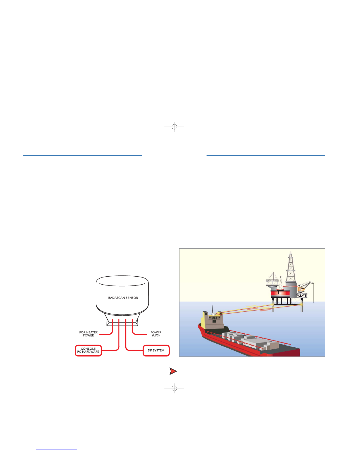
RadaScan has been designed for permanent installation and quick/easy
operation. A RadaScan system comprises of 3 major components as follows:
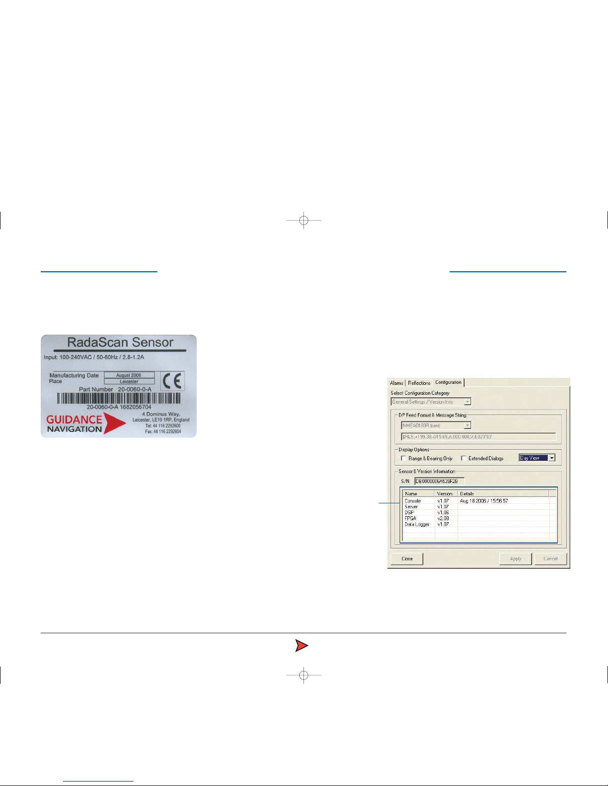
•The RadaScan Sensor. A scanning transceiver unit with integral power
supply and processing electronics for installation in a prominent external
location in order to view available transponder. The Sensor is connected
to the vessel DP system by a serial RS422 or Ethernet link.
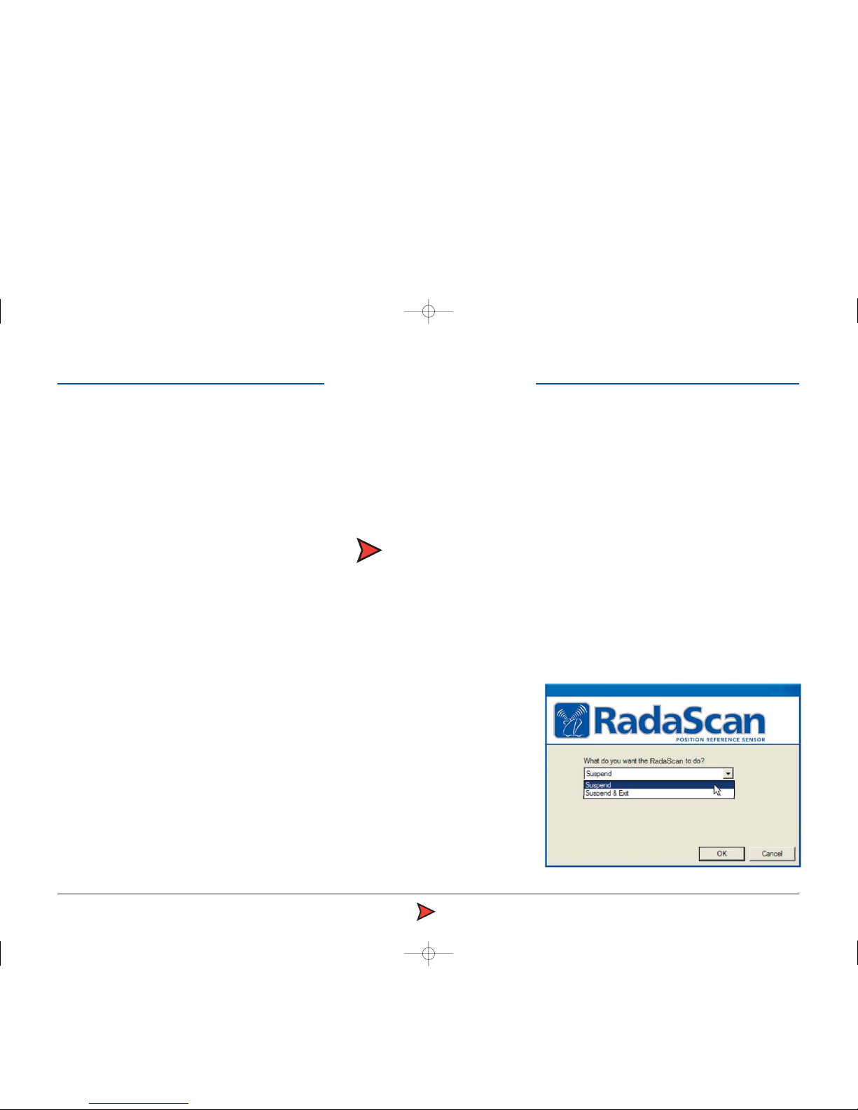
•The RadaScan Console. A system control and display application running
under Microsoft Windows XP on a standard PC. This allows full control of
the system together with graphical and data display of system status. An
Ethernet link connects the Sensor to
the Console PC.
•RadaScan Transponder/Target.
A passive self contained battery
powered electronics module for
temporary, semi-permanent or
permanent installation on the
target vessel. RadaScan
transponders are ATEX
certified as intrinsically
safe.
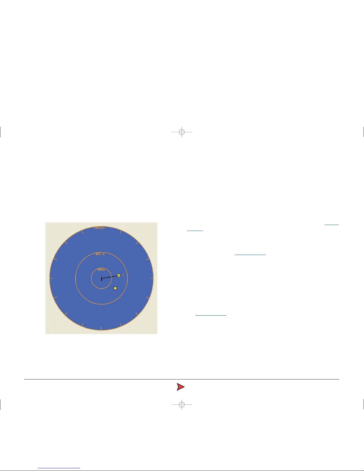
Principles of Operation
The RadaScan sensor emits a low power radar beam. The beam is received
by a RadaScan transponder and instantaneously reflected back to the sensor.
The sensor uses the reflection to accurately calculate the distance (range) and
direction (bearing) to the transponder. This positional data is automatically
sent to the DP system. The transponder reflection is retro-reflective in
character (ie it is sent in the same direction as received beam). The
transponder is also able to encode the reflection with a transponder identity
code. This code allows the sensor to recognise the reflection as genuine and
so aid easy operation and improve tracking reliability.
RadaScan unit
RadaScan equipped vessel
RadaScan transponders
Introduction