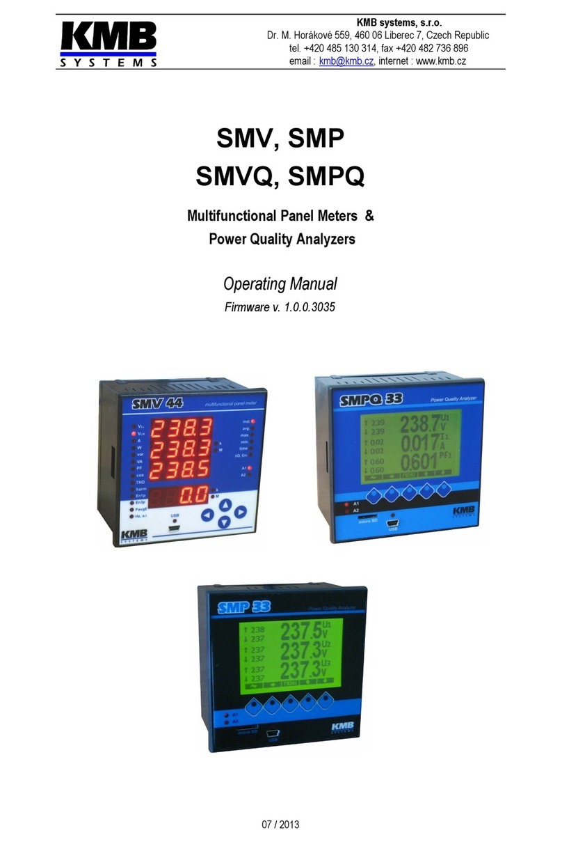
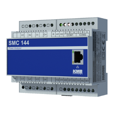
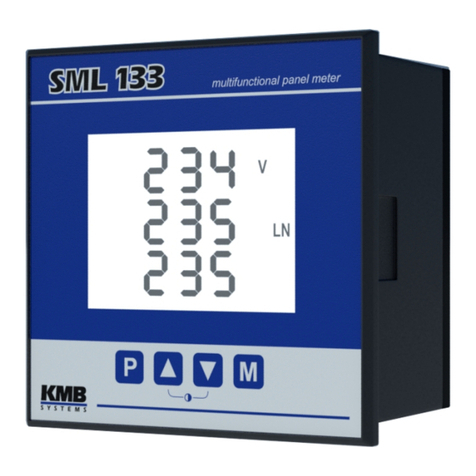
KMB SMY 133 User manual

KMB systems, s.r.o.
Dr. M. Horákové 559, 460 06 Liberec 7, Czech Republic
tel. 420 485 130 314, fax 420 482 736 896
email : [email protected], internet : www.kmbsystems.eu
SMY133, SMY134, SMP133
Multifunctional Panel Meters
Operating Manual
Document
revision
Release
date
Valid for versions
hardware bootloader firmware ENVIS
1.3 13.5.2020 2.6 4.0 3.0.35 / 3.6.4 1.8 / 1.9

SMY133-SMY134-SMP133 Operating Manual
LIST OF ONTENTS
1. GENERAL...........................................................................6
1.1 Differences between SMY133, SMY134 and SMP133..............................................................................7
2. INSTALLATION..................................................................8
2.1 Meaning of the symbols used on instrument..........................................................................................8
2.2 Physical...................................................................................................................................................... 8
2.3 Instrument onnection.............................................................................................................................. 9
2.3.1 Safety Grounding (SMP133 only)......................................................................................................... 9
2.3.2 Power Supply...................................................................................................................................... 10
2.3.3 Measured Voltages............................................................................................................................. 10
2.3.4 Measured Currents............................................................................................................................. 10
2.3.4.1 Current Type Current Inputs Instruments ( Models „X/5A“, „X/100mA“ )....................................10
2.3.4.2 Voltage Type Current Inputs Instruments ( Models „X/333mV“ ).................................................11
2.3.5 Other Inputs/Outputs........................................................................................................................... 11
3. OMMISSIONING.............................................................12
3.1 Setup......................................................................................................................................................... 12
3.1.1 Measured Electrical Quantities Installation Setup...............................................................................12
3.1.1.1 Setup Example............................................................................................................................ 13
4. DETAILED DES RIPTION...............................................15
4.1 Basic Functions....................................................................................................................................... 15
4.2 Manipulation and Setting........................................................................................................................ 15
4.2.1 Data Area – Status Bar - Toolbar........................................................................................................ 15
4.2.2 Main Menu.......................................................................................................................................... 16
4.2.3 Main Data Group................................................................................................................................ 16
4.2.4 Actual & Average Data Groups...........................................................................................................16
4.2.5 Electricity meter.................................................................................................................................. 17
4.2.6 Oscillograms....................................................................................................................................... 17
4.2.7 Phasor Diagram.................................................................................................................................. 17
4.2.8 Harmonics & THDs............................................................................................................................. 17
4.2.9 Power Quality & Voltage Events......................................................................................................... 18
4.2.10 Ripple Control Signal........................................................................................................................ 18
4.2.11 Instrument Settings ( Parameters )...................................................................................................19
4.2.11.1 Display Setting........................................................................................................................... 19
4.2.11.2 Installation Setting..................................................................................................................... 19
4.2.11.3 Remote Communication Setting................................................................................................ 19
4.2.11.4 Clock Setting............................................................................................................................. 19
4.2.11.5 Average Values Processing Setting.......................................................................................... 20
4.2.11.6 Embedded Electricity Meter Setting..........................................................................................20
4.2.11.7 Power Quality & Input/Output Setting.......................................................................................20
4.2.11.8 Ripple Control Signal Setting.................................................................................................... 20
4.2.12 Instrument Lock............................................................................................................................... 21
4.2.12.1 Locking from the Instrument Panel............................................................................................ 21
2

SMY133-SMY134-SMP133 Operating Manual
4.2.12.2 Unlocking from the Instrument Panel.........................................................................................21
4.2.12.3 Locking/Unlocking by the User Management............................................................................21
4.2.13 Instrument Information..................................................................................................................... 22
4.3 Description of Operation......................................................................................................................... 23
4.3.1 Method of Measurement..................................................................................................................... 23
4.3.1.1 Voltage Fundamental Frequency Measurement Method.............................................................23
4.3.1.2 Voltage and Current Measurement Method.................................................................................23
4.3.1.3 Harmonics and THD Evaluation Method......................................................................................24
4.3.1.4 Power, Power Factor and Unbalance Evaluation Method............................................................24
4.3.1.5 Temperature............................................................................................................................... 26
4.3.1.6 “ The Fixscan” Mode................................................................................................................... 26
4.3.1.6.1 Function............................................................................................................................... 27
4.3.2 Measured Values Evaluation and Aggregation...................................................................................28
4.3.2.1 Actual Values Evaluation and Aggregation..................................................................................28
4.3.2.2 Average Values Evaluation.......................................................................................................... 28
4.3.2.2.1 Maximum and Minimum Average Values............................................................................29
4.3.2.3 Recorded Values Aggregation..................................................................................................... 30
4.3.3 Embedded Electricity Meter................................................................................................................ 30
4.3.3.1 Electric Energy Processing.......................................................................................................... 30
4.3.3.1.1 Standard Energy Presentation............................................................................................ 30
4.3.3.1.2 Customizable Energy Screen..............................................................................................31
4.3.3.1.3 Recorded Values of Energy Aggregation.............................................................................32
4.3.3.2 Maximum Demand Processing.................................................................................................... 32
4.3.3.2.1 Fixed Window MD Processing, Last Demand and Estimated Demand................................33
4.3.3.2.2 Maximum Demand Presentation..........................................................................................33
4.4 Embedded Auxiliary Voltage Backup (SMP 133 only)...........................................................................34
5. RESIDUAL URRENT MONITORING (R M).................35
5.1 Measuring Transformers for the R M.................................................................................................... 35
5.1.1 Electrical Safety.................................................................................................................................. 35
5.1.2 Standard RCTs with AC-Current Output.............................................................................................35
5.1.2.1 Overcurrent Protection................................................................................................................ 35
5.1.3 Special RCTs with DC-Current Output................................................................................................36
5.2 R M Inputs onnection.......................................................................................................................... 36
5.3 R M Setup & Presentation...................................................................................................................... 37
5.4 Tips & Hints.............................................................................................................................................. 38
6. INPUTS & OUTPUTS........................................................39
6.1 onnection of the I/Os............................................................................................................................ 40
6.1.1 Digital Output (DO, RO) Connection................................................................................................... 41
6.1.2 Digital Input (DI) Connection............................................................................................................... 42
6.1.3 Analog Inputs Connection................................................................................................................... 42
6.1.4 External Pt100 Temperature Sensor Connection................................................................................42
6.2 I/O Setup................................................................................................................................................... 43
6.2.1 I/O Actions.......................................................................................................................................... 44
6.2.1.1 Digital Output (Standard, DO/RO)............................................................................................... 44
6.2.1.2 Alarm Light (A)............................................................................................................................. 45
6.2.1.3 Pulse Output (PO)....................................................................................................................... 45
6.2.1.4 Pulse Switch................................................................................................................................ 45
3

SMY133-SMY134-SMP133 Operating Manual
6.2.1.5 Frequency Counter (FC).............................................................................................................. 46
6.2.1.5.1 Frequency Mode.................................................................................................................. 46
6.2.1.5.2 PWM Mode.......................................................................................................................... 46
6.2.1.6 Pulse Counter (PC)..................................................................................................................... 46
6.2.1.7 Analog Input (AI).......................................................................................................................... 47
6.2.1.8 Analog Output (AO)..................................................................................................................... 47
6.2.1.9 Send Message............................................................................................................................. 48
6.2.1.10 Send Email................................................................................................................................ 48
6.2.1.11 Hour Meter (HM)........................................................................................................................ 49
6.2.1.12 Time Synchronization................................................................................................................ 50
6.2.1.13 Archive Control.......................................................................................................................... 50
6.2.1.14 General Oscillogram.................................................................................................................. 50
6.2.1.15 Variable..................................................................................................................................... 51
6.2.2 I/O Conditions..................................................................................................................................... 52
6.2.2.1 Digital Input Condition................................................................................................................. 52
6.2.2.2 Measured Quantity Condition......................................................................................................52
6.2.2.3 Device State Condition................................................................................................................ 53
6.2.2.4 RCM Condition............................................................................................................................ 54
6.2.2.5 Time Condition............................................................................................................................ 54
6.2.2.6 Variable Condition....................................................................................................................... 54
6.3 I/O Actual Data Presentation................................................................................................................... 55
6.3.1 Digital and Analog I/O......................................................................................................................... 55
6.3.2 Pulse Counters................................................................................................................................... 56
6.4 I/O Block Processing............................................................................................................................... 56
6.4.1 Digital Inputs....................................................................................................................................... 56
6.4.1.1 Digital Input Filter......................................................................................................................... 56
6.4.1.2 Digital Input as Frequency Counter.............................................................................................57
6.4.1.2.1 “Frequency” Mode................................................................................................................ 57
6.4.1.2.2 “PWM” Mode........................................................................................................................ 57
6.4.1.3 Digital Input as Pulse Counter.....................................................................................................57
6.4.1.4 Digital Input as Frequency & Pulse Counter................................................................................57
6.4.2 Digital Outputs.................................................................................................................................... 57
6.4.2.1 Pulse Outputs.............................................................................................................................. 57
7. OMPUTER ONTROLLED OPERATION......................58
7.1 ommunication Links.............................................................................................................................. 58
7.1.1 Local Communication Link.................................................................................................................. 58
7.1.2 Remote Communication Links............................................................................................................ 58
7.1.2.1 RS-485 Interface (COM).............................................................................................................. 58
7.1.2.1.1 Communication Cable......................................................................................................... 59
7.1.2.1.2 Terminating Resistors......................................................................................................... 59
7.1.2.2 Ethernet (IEEE802.3) Interface....................................................................................................59
7.2 ommunication Protocols...................................................................................................................... 59
7.2.1 KMB Communications Protocol......................................................................................................... 59
7.2.2 Modbus-RTU Communications Protocol............................................................................................60
7.2.3 M-Bus Communications Protocol........................................................................................................ 60
7.3 Embedded Webserver.............................................................................................................................. 60
8. FIRMWARE EXTENSION MODULES..............................61
8.1 Power Quality Module.............................................................................................................................. 61
4

SMY133-SMY134-SMP133 Operating Manual
8.2 Ripple ontrol Signal Module................................................................................................................. 61
8.3 General Oscillogram Module................................................................................................................... 62
8.4 Modbus Master Module........................................................................................................................... 62
8.5 Ethernet-to-Serial Module........................................................................................................................ 63
8.6 UDP Push Module.................................................................................................................................... 63
9. EXAMPLES OF ONNE TIONS.....................................64
10. MANUFA TURED MODELS AND MARKING...............72
11. TE HNI AL SPE IFI ATIONS.....................................73
12. MAINTENAN E, SERVI E............................................84
5

SMY133-SMY134-SMP133 Operating Manual
1. General
Measurement & Evaluation
• three measurement voltage inputs, star / delta / Aron connection
• three/four measurement current inputs for CTs nominal secondary output of 5/1 A or 0.1 A
• 10/12 periods evaluation cycle (200 ms at 50/60 Hz)
• continuous ( gap-less) measurement of voltage and current
• evaluation of harmonic components up to 50th
• fixed window / floating window average values of all evaluated quantities with minimum &
maximum values registration
• built-in electricity meter :
◦four-quadrant counters for both active and reactive energies at three tariffs
◦single phase and three phase energies
◦maximum of average active power value registration (maximum demand)
•built-in thermometer
•residual current inputs (certain models only)
ommunication
•USB 2.0 communication port for fast data acquisition, configuration and firmware upgrades
•optional remote communication interface ( RS 485 / Ethernet / M-Bus)
•proprietary protocol with free data acquisition software ENVIS
•MODBUS RTU /TCP protocols for simple integration with third party SCADA software
•embedded webserver ( for instruments with Ethernet interface )
Datalogging apabilities
•battery backed real time circuit (RTC)
•record interval from 0.2 second up to 1 hour
•high memory capacity for programmable recording of aggregated measurement values
•automated electricity meter readings at preselected time intervals
Inputs & Outputs ( Depending on Instrument Model )
•digital outputs (relays or solid state)
•digital inputs
•0 ÷ 20 mADC analog inputs
•Pt100 temperature sensor input
Design
•96x96 mm plastic box for panel mounting
•TFT-LCD colour graphic display, 5 keys
6

SMY133-SMY134-SMP133 Operating Manual
1.1 Differences between SMY133, SMY134 and
SMP133
SMY133 SMY134 SMP133
number of current inputs 3 4 3
current crest factor at INOM standard – 2.0 standard – 2.0
high – 17
(for recording of
transient events)
measurement sampling
frequency at 50 / 60 Hz stand. model : 6.4 / 5.76 kHz
model „G2“ : 25.6 / 23.04 kHz 25.6 / 23.04 kHz 25.6 / 23.04 kHz
measurement category of
voltage inputs
(model “230”)
300V CATIII 300V CATIII 300V CATIV
voltage & current
measurement uncertainty
class according
IEC 61557-12
0.5 0.2 0.2
embedded auxiliary
voltage backup no no yes
protection class according
IEC 61140 II - II - I -
Other features are common.
7

SMY133-SMY134-SMP133 Operating Manual
2. Installation
2.1 Meaning of the symbols used on instrument
Warning – read operating manual !
AC – alternating voltage
DC – direct voltage
CE marking guarantees compliance with the European directives and regulations
The instrument must not be disposed of in the normal unsorted municipal waste
stream
Basic insulation instrument (protection class I)
Double or reinforced insulation instrument (protection class II)
2.2 Physical
The instrument is built in a plastic box to be installed in a distribution board panel. As a rule, the panel
is a part of a switchboard door - then the installation must be such that the switchboard door can be
closed under all conditions of use. In any case, it must be ensured that only the front panel of the
instrument is accessible to laypersons. Therefore, if the switchgear is located in an area accessible to
laypersons, the switchgear door or panel must only be opened by means of a tool, or the door must be
locked.
8
Fig. 2.1a : Panel Mounting
switchboard outer side
accessible to laymen
minimum protection IP40
switchboard inner side
inaccessible to laymen
protection IP20 or lower

SMY133-SMY134-SMP133 Operating Manual
The instrument’s position must be fixed with locks.
Natural air circulation should be provided inside the distribution board cabinet and in the instrument’s
neighbourhood no other instrumentation should be installed.
Fig. 2.1b : Space around the Instrument
Especially underneath the instrument, no other instrumentation that is source of heat should be
installed or the temperature value measured may be false.
2.3 Instrument onnection
2.3.1 Safety Grounding (SMP133 only)
As the SMP133 is safety class I type instrument, it must be grounded.
The instrument is equipped with the faston-type terminal 6.3 x 0.8 mm, marked (sometimes
referenced as PE-terminal).Corresponding crimp-type receptacle is delivered with the instrument as
standard accessory.
Fig. 2.2 : SMP 133 Grounding
The terminal must be connected with the PE (or PEN) protection ground conductor (bare or with
green/yellow coloured insulation).
Recommended wire type : H07V-U (CY)
Recommended minimum conductor cross-section : 2.5 mm2
Maximum conductor cross-section : 4 mm2
9

SMY133-SMY134-SMP133 Operating Manual
For safet reasons, the instrument must be grounded before connection of other signals!
2.3.2 Power Supply
The supply voltage (in range according technical specifications) connects to terminals AV1 (No. 9) and
AV2 (10) via a disconnecting device (switch – see wiring diagram). It must be located at the
instrument’s proximity and easily accessible by the operator. The disconnecting device must be
marked as such. A two-pole circuit breaker with the C-type tripping characteristics rated at 1A makes a
suitable disconnecting device. Its function and working positions, however, must be clearly marked.
In case of DC supply voltage the polarity of connection is generally free, but for maximum
electromagnetic compatibility the grounded pole should be connected to the terminal AV2.
Recommended wire type : H07V-U (CY)
Recommended minimum conductor cross-section : 1.5 mm2
Maximum conductor cross-section : 2.5 mm2
2.3.3 Measured Voltages
The phase voltages measured are connected to terminals U1 (12), U2 (13), U3 (14), the common
terminal to connect to the neutral wire is identified as N (11; it stays free at delta- (3-D) and Aron- (A)
connections). It is suitable to protect the voltage lines measured for example with 1A fuses. Measured
voltages can also be connected via instrument voltage transformers.
Recommended wire type : H07V-U (CY)
Recommended minimum conductor cross-section : 1.5 mm2
Maximum conductor cross-section : 2.5 mm2
2.3.4 Measured urrents
The instruments are designed for indirect current measurement via external CTs only. Proper current
signal polarity (S1 & S2 terminals) must be observed. You can check the polarity by the sign of phase
active powers on the instrument display (in case of energy transfer direction is known, of course).
It is necessary to set the CT-ratio – see example below.
The I2 terminals stay free in case of the Aron (A) connection.
2.3.4.1 urrent Type urrent Inputs Instruments ( Models „X/5A“,
„X/100mA“ )
The current signals from 5A or 1A (or 0.1A for the „X/100mA“ models) instrument current transformers
must be connected to the terminal pairs I11, I12, I21, I22, I31, I32 (No. 1 ÷ 6). At the “134” model, you
can connect the 4th current signal too to the terminals I41, I42 (No. 7 ÷ 8).
Recommended wire type: H05V-U (CY)
Recommended minimum conductor cross-section :
•“X/5A” instruments : 2.5 mm2
•“X/100mA” instruments : 0.75 mm2
Maximum conductor cross-section : 2.5 mm2
10

SMY133-SMY134-SMP133 Operating Manual
2.3.4.2 Voltage Type urrent Inputs Instruments ( Models
„X/333mV“ )
The instruments are equipped with separate connectors for particular measuring current input. Each
connector has three terminals. Function of the terminals is described in following table :
“X/333mV“ Models Current Inputs Connection
terminal No. signal
62 SI1 … signal corresponding to I1 current (in phase L1), CT terminal “S1”
65 SI2 … I2-S1 (phase L2)
68 SI3 … I3-S1 (phase L3)
63, 66, 69 SG …common pole of the I1 ÷I3 signals (CT terminals “S2”) and negative pole of the
5V built-in auxiliary power supply for current sensors (the terminals are
interconnected)
61, 64, 67 SP... positive pole of the 5V built-in auxiliary power supply for current sensors (the
terminals are interconnected)
The instruments are designed for cooperation with current transformers with output nominal voltage of
333 millivolts. They can be also used with flexible current sensors (Rogowski coils) with embedded
integrator of appropriate voltage output signal.
The CTs must be connected with two-wire twisted cable. Again, proper current signal polarity (CT
secondary terminals S1, S2) must be observed.
Recommended wire type : twisted pair, for example KU03G24 ( Nexans )
Recommended minimum conductor cross-section: 0.2 mm2
Maximum conductor cross-section: 1.5 mm2
Maximum length of the cable is 3 metres !
The flexible current sensors with embedded integrator usually require a power supply. For such
purpose the instruments are equipped with auxiliary power supply 5V. Maximum load of each sensor
connected is 20 mA.
Connection of standard CTs with 5A or 1A nominal output current to the „X/333mV“
instruments s forbidden !!! Otherwise the instrument can be damaged !!!
2.3.5 Other Inputs/Outputs
Connection of residual current inputs, other inputs, outputs and communication links are described in
appropriate chapters further below.
11

SMY133-SMY134-SMP133 Operating Manual
3. ommissioning
3.1 Setup
When switching on the power supply, the instrument will display manufacturer's logo for short time and
after that, one of actual data screen - for example the line-to-neutral voltages one - is displayed :
At this moment it is necessary to set instrument parameters that are essential for proper instrument
measurement (so called Installation group) :
•mode of connection ( direct measuring or via metering voltage transformers )
•type of connection ( star, delta, Aron )
•ratio of CTs, VTs and their multipliers (if used)
•nominal voltage UNOM and nominal frequency fNOM
•INOM, PNOM (not mandatory, but recommended)
3.1.1 Measured Electrical Quantities Installation Setup
For the proper data evaluation it is necessary to set all of the Installation Setting group
parameters.
•onnection Mode determines if voltage signals are connected directly or if voltage
transformers are used.
•onnection Type needs to be set according network configuration – wye (or star, Y ) or
delta ( D , if neutral voltage potential not connected ). Usually, all of three phases are
connected so choose 3-Y or 3-D. For Aron connection set 3-A. For single-phase connection,
set 1-Y.
•T ( TN, TR M) - ratios must be specified, in case of “via VT” connection mode VT-ratio too.
The T is valid for currents I1, I2 and I3. If the fourth current input or residual current inputs
are used, appropriate ratios TN / TR M must be set too.
CT ratios can be set in form either …/ 5A or …/ 1A or …/ 333mV.
The VT-ratio must be set in form Nominal primar voltage / Nominal secondar voltage . For
higher primary voltage values the U-multiplier must be used too.
•I- and U-Multipliers - You can modify any CT- / VT-ratio with this parameters. For example,
to get better precision when using overweighted CTs, you can apply more windings of
measured wire through the transformer. Then you must set the multiplier. For example, for 2
windings applied, set the multiplier to 1/2 = 0.5 .
For standard connection with 1 winding, the multiplier must be set to 1.
The TN and TR M ratios have their extra IN – and IR M–Multipliers.
12

SMY133-SMY134-SMP133 Operating Manual
Instead the IRCM–multiplier, the 0/20mA or the 4/20mA RCT- type can be set – see the RCM
chapter below.
•Nominal Frequency fNOM - the parameter must be set in compliance with the measurement
network nominal frequency to either 50 or 60 Hz, optionally to „DC-500“ (= Fixscan mode).
• Nominal Voltage UNOM, Nominal urrent INOM, Nominal Power PNOM - For the presentation
of quantities in percent of nominal value, alarms operation, voltage events detection and
other functions it is necessary to enter also the nominal ( primary ) voltage UNOM, nominal
current INOM and nominal apparent three-phase power (input power) of the connected load
PNOM ( in units of kVA ) Although the correct setup has no effect on measuring operation of the
instrument, it is strongly recommended to set at least the UNOM correctly.
Correct setting of the INOM and the PNOM is not critical, it influences percentage representation
of powers and currents and statistical processing of measuring in the software only. If
measured network node rating is not defined, we recommend to set their values, for example,
to the nominal power of source transformer or to the maximum supposed power estimated
according current transformers ratio, etc.
The UNOM is displayed in form of phase/line voltage.
3.1.1.1 Setup Example
Following example explains how to adjust the CT ratio :
Assuming that the conversion of used CT for inputs of current L1 to L3 is 750/5 A. To edit the
parameters, press the , navigate to the Menu-Settings with the buttons
and and then choose it with the . In the Setting window choose Setting-
Installation option. The Setting-Installation window appears.
In the window navigate down to the current transformer ratio parameter ( CT ) and choose with the
.
Now you can type new value of the parameter : with the you can move from a digit to
another one and to set each digit to target value using the and . At the end press
the and the parameter is set.
You can set other parameters in the same way.
After all of the parameters of the group correctly set, return back to an actual data screen with the
(escape) button and confirm saving of changes with the .
13

SMY133-SMY134-SMP133 Operating Manual
Now you can browse through displayed actual values with the and and check if
they correspond with reality.
For proper CT connection checking, ou can use phasor diagram screen.
After measured quantities checked, other parameters (of RTC, averaging, remote communication etc.)
can be set .
14

SMY133-SMY134-SMP133 Operating Manual
4. Detailed Description
4.1 Basic Functions
The instruments evaluate all of usual electric quantities like line-to-line and phase voltages, currents,
active, reactive and apparent powers, power factors, voltage and current THDs and harmonic
components, active and reactive energy, average power maximums, frequency etc. Furthermore,
temperature is measured with built-in sensor. Optionally, the second temperature can be measured
with an external Pt100 sensor at appropriate instrument models.
The instruments are fitted with inputs for connection of three voltage signals, three or four current
signals (for connection of external CTs with either 5/1 AAC or 0.1 AAC or 333 mVAC nominal secondary
signal) and separate AC/DC power supply input. They can be used in both low and high voltage power
grids.
The instruments feature three-rate tariff electricity meter with four-quadrant counters for both active
and reactive energies and maximum average active power ( maximum demand ) registration.
Advanced models store all results for actual and last month too and a separate archive dedicated for
automated meter readings can record actual status in preselected intervals.
Certain models can be used for residual current monitoring too.
The instruments are equipped with battery backuped real-time circuit (RTC) and high capacity „Flash"
type memory for measured data and events recording.
The USB 2.0 communication link can be used for the instrument adjusting and recorded data transfer.
For remote access, optional RS-485 or Ethernet or M-Bus communication interface is available. The
instruments with Ethernet interface have embedded webserver.
Basic specifications of the instrument can be set up by using the inbuilt keyboard and the display. With
the ENVIS program supplied as standard you can, via any of communication link, adjust the
instrument and transfer recorded data. In addition to the instrument adjustment, ENVIS program
allows you to display, view and archive the measured courses in the graphic form, as well as a
number of other features.
4.2 Manipulation and Setting
4.2.1 Data Area – Status Bar - Toolbar
Instrument's screen consists of two parts : a data area and a status bar / toolbar area.
After instrument's startup the status bar appears below data area as default. The status bar contains
following information :
15
Fig. 4.1: Data Area, Data Area, Status Bar, Toolbar
indicator
data area
toolbar status bar

SMY133-SMY134-SMP133 Operating Manual
• … A1 and A2 alarm lights. After the bell icon, two targets represent actual state of
the lights; the first one – A1 – is switched on on the example, the A2 is just switched off. This
information appears only when either A1 or A2 function is set in the I/O management setup
(see below).
• … digital I/O state. The instrument on example is equipped with four bidirectional
inputs(DI)/outputs(DO) and either the DI3 input or DO3 output is just active.
Instruments equipped with unidirectional I/Os uses icon for inputs and icon for
outputs.
• … local time ( hours : minutes)
As soon as any button is pressed, a toolbar replaces the status bar. The toolbar determines function of
individual buttons and changes dynamically by a context. If no manipulation with buttons for a longer
period the toolbar is replaced with the status bar.
In special cases a flashing indicator can appear at upper right corner of the data area. It indicates
following cases :
• … Frequency measurement not yet finished or out of range. In such cases measured
signals are scanned according preset nominal frequency fNOM and measured values can be
incorrect. Check fNOM parameter setting.
• … At least one of voltage or current input overloaded
4.2.2 Main Menu
By pressing the , a Main menu window appears. With the
and you can browse through the menu and
select a desired action with the or return back using the
(escape) button.
All other buttons but the are context dependent and
variable, but the is accessible from nearly every window
which helps to quick orientation.
Next chapters describe individual main menu options.
4.2.3 Main Data Group
This data group of screens is configurable by user. You can choose data screens you are most
interested in and place them in this group for easy access. Use the ENVIS-DAQ program for the
setup.
4.2.4 Actual & Average Data Groups
Actual / Average values of measured data in numeric form are displayed in the groups,
respectively. For detailed description of the actual values presentation see chapter Displa
Actual Values Evaluation and Aggregation further below.
All the values are identified with a quantity name and a quantity unit.
An U/I/P/Q summar window is an exception – the quantity unit is not
displayed (only a k / M / G multiplier is).
At the last row, there is actual values of voltage unbalance u2 [%]
and frequency f [Hz].
The 2nd exception is the I/O actual data window . For detailed
description see the chapter I/O Actual Data Presentation.
16
Fig. 4.3 : Actual Data
Summar Window
Fig. 4.2: Main Menu

SMY133-SMY134-SMP133 Operating Manual
4.2.5 Electricity meter
In this data group you can check active & reactive energies registered in all quadrants.
Next, maximum values of average three-phase active power including time stamps – so called
maximum demands. For details see the chapter Embedded Electricit Meter.
Furthermore, there is the pulse counters actual state table. For detailed description see the chapter I/
O Actual Data Presentation.
4.2.6 Oscillograms
At this group there are actual waveshapes of all measured voltages and currents. With the
and you can toggle between votage and current screen.
They are also displayed effective values of the voltages/currents and maximum of their peak values
Up/Ap.
4.2.7 Phasor Diagram
Diagram of actual voltage and current fundamental harmonic phasors.
Voltage phasor angles φ are absolute, current phasor angles are
relative to appropriate voltage phasor (Δφ).
Phase order can be checked here too (indicated as 1-2-3 or 1-3-2 ).
4.2.8 Harmonics & THDs
Actual harmonic components of all voltage and current signals in graphic ( histogram ) format. They
are expressed in per cent of fundamental harmonic component.
Only odd components from the 3rd to 25th are displayed; for full spectrum of harmonics use ENVIS-
DAQ program.
In the upper right corner, there are values of THD of individual phases.
17
Fig. 4.4 : Voltage Waves Fig. 4.5 : Current Waves
Fig. 4.6 : Phasor Diagram
Fig. 4.7 : Voltage Harmonics Fig. 4.8 : Current Harmonics

SMY133-SMY134-SMP133 Operating Manual
4.2.9 Power Quality & Voltage Events
This data group is available when appropriate firmware module is installed only.
On the first screen, there is “calendar” of power quality evaluation according the EN 50160 standard.
Each day is marked with either or depending on that if power quality during the day was in
compliance with the standard or not.
Next, there is the table of voltage events (VE). The events are sorted according magnitude and
duration of each sag/swell/interruption and in the table you can check number of particular events
registered since last clear. You can clear the VE-table in the PQ-setup screen.
Detailed information of the PQ evaluation and the voltage events can be analyzed after downloaded
into the ENVIS program.
4.2.10 Ripple ontrol Signal
This data group is available when appropriate firmware module is installed only.
At the screen you can check live graph of ripple control signal (mains signalling, URC) of chosen
frequency. At the example there is starting part of a telegram of frequency 183 Hz on the L1 phase
(URC1).
With the and you can pass through all of phases measured. With the
and you can toggle into the measured data table. There you can check :
•the upper part : actual and average (3 second floating window) values of the URC1, URC2, URC3
ripple control signals
•the bottom part : average, maximum and minimum voltage of detected pulses (= when signal
exceeds treshold URCSTR) registered during the last telegram.
With the and you can scroll through all measured phases.
The fR frequency and the UR TR treshold voltage can be set in the RCS-setup screen.
18
Fig. 4.9 : Power Qualit
Calendar
Fig. 4.10 : Voltage Events
Table
Fig. 4.11 : Ripple Control
Signal Graph
Fig. 4.12 : Ripple Control
Signal DataTable

SMY133-SMY134-SMP133 Operating Manual
4.2.11 Instrument Settings ( Parameters )
In this group most of presetable parameters can be viewed and edited. Other parameters
can be accessed via communication link using the ENVIS-DAQ program only.
If any of setting window is viewed, an instrument automatically reswitches to actual data display during
an approx. 1 minute if no manipulation with buttons is carried out.
Following chapters explain the meaning of particular groups of parameters.
4.2.11.1 Display Setting
•ontrast … Can be set in range 0 – 100%
•Brightness … The set level of brightness is activated whenever any button is pushed. If no
manipulation with buttons for approx. 5 minutes, the brightness is automatically decreased in
order to decrease instrument power dissipation and to spare display lifetime.
•Language … In addition to the basic English version, other language versions can also be
set.
•Display refresh cycle … Actual values refresh period. For details see chapter Displa
Actual Values Evaluation and Aggregation.
•Display Resolution … Actual & average data groups format be set to 3 or 4 significant
figures.
4.2.11.2 Installation Setting
All parameters of this group are explained in chapter Measured Electrical Quantities Installation Setup.
above ( the Commissioning part ).
4.2.11.3 Remote ommunication Setting
Communication parameters for various interface types differ from each other :
OM (RS-485) interface :
•ommunication Address
•ommunication Rate …in Bauds (Bd)
•Data Bits … including parity bits! Set to 8 for KMB-protocol; set to 9 when parity bit is used
(Modbus-protocol, for example)
•Parity …none/even/odd
•Stop Bits … set to 1 (usually)
Ethernet interface :
•DH P ... activation of dynamic IP-address allocation
•IP Address …internet protocol address
•Subnet Mask …subnet mask
•Default Gateway …default gateway
•KMB-port … communication port used for KMB protocol communication (2101 as default)
•Web-port … communication port used for webserver communication (80)
•Modbus-port … communication port used for Modbus protocol communication (502)
Nex information can be found in chapter Computer Controlled Operation below.
4.2.11.4 lock Setting
•Date & Time … Local date and time
•Time Zone … The time zone should be set according location of an instrument
during installation. Correct setting is essential for proper local time interpretation.
19

SMY133-SMY134-SMP133 Operating Manual
•Daylight Saving … This option controls automatic winter/summer local time
switching
•Time Synchronization … As the built-in real time circuit has limited accuracy while free
running, with this option it is possible to keep the RTC time in synchronism with an external
precise time source. The RTC can be synchronized by :
•Pulse Per Second / Minute (PPS / PPM ) … A digital input is used for time
synchronization from an external source at this case. The instrument sets the RTC
to the nearest second or minute as soon as a synchronization pulse is detected.
Second-, Minute-, quarter-hour- or hour- synchronization pulses are accepted.
•NMEA Message ...If an instrument is equipped with the RS-485 remote
communication interface an external ( usually GPS-based ) time receiver can be
connected to. The receiver must be set to transmit the “ZDA”- or “RMC ”-message
(NMEA 0183 protocol). The communication interface must be set appropriately
(usually 4800 Bd, 8 bits, 1 stopbit).
•NTP Server ...The option can be used if an instrument is equipped with the Ethernet
communication link and a NTP-server is available in the network. Set IP-adress of
the server. Then time synchonization is performed every hour.
•Network Frequency … For this option, the nominal frequency fNOM parameter must
be set properly. Otherwise the synchronization will not work.
Warning : When editing clock parameters, it must be taken into account that internal data
archives are affected : when changing the date or time, all archives are cleared !
4.2.11.5 Average Values Processing Setting
In this parameter group average values processing for the U/I-, P/Q/S- and, optionally RCM-group of
measured quantities can be set. Detailed explanation can be found in the chapter Average Values
Evaluation further below.
4.2.11.6 Embedded Electricity Meter Setting
In this group parameters concerning electric energy registration and maximum active power demand
processing (MD) can be set. For detailed parameter description see the chapter Embedded Electricit
Meter further below.
4.2.11.7 Power Quality & Input/Output Setting
There are only overviews of parameters. To edit them, use the ENVIS-DAQ program.
You can only clear the voltage events table in the power quality setup group.
4.2.11.8 Ripple ontrol Signal Setting
•Method … Method of the signal evaluation can be set either to Filter or in compliance with
the IEC61000-4-30 standard
•fR … frequency of the ripple control signal in Hz
•UR unit … ripple control voltage unit : either V or percent of UNOM
•UR threshold (UR TR) … minimum signal level to be recognized as „pulse“. Relevant for
telegram detection, signal below the threshold is recognized as „gap“.
20
Other manuals for SMY 133
2
This manual suits for next models
2
Table of contents
Other KMB Measuring Instrument manuals
Popular Measuring Instrument manuals by other brands

Systec
Systec deltawaveVER2 user manual

CTC Union
CTC Union MMX2000 Series product manual

Siemens
Siemens FIDAMAT 6 operating instructions

Pacific Data Systems
Pacific Data Systems DPM-RT-2 operating manual

Endress+Hauser
Endress+Hauser Prosonic T FMU30 Brief operating instructions

Suparule
Suparule 600E Instructions on the Safe Use