3
5. Turn adjuster (C) fully
ANTI-CLOCKWISE (to the left).
6. Adjust (D) until the display reads Zero
7. Turn adjuster (C) fully CLOCKWISE
(to the right) and make a note of the
reading on the display.
It is now necessary to calculate the ZERO
POINT for the Gastester.
Use the following equation to calculate:
Where X = reading from point 6 above
Take X and divide by two, then subtract
two, this equals the ZERO POINT
ZERO POINT = (X/2)-2
8. Now turn adjuster (C) until the display
equals the ZERO POINT
9. Turn adjuster (D) until the display
equals 00.0
2
G4125
Supplementary adjustment procedure
The procedure described below should only be used when the Gastester cannot be adjusted
to show the normal pre gas test reading of 2.0%
Only if the Gastester displays the symptoms described in section 4 below should this
procedure be used.
It should also be noted that damage caused to the Gastester during this procedure is entirely
at the operator own risk. If in doubt please return the unit to your supplier for calibration and
testing.
Pre-test set-up (as described in G4125 instructions)
1. Place the Gastester on a level, vibration free surface.
2. Connect to a 12 volt source and allow the Gastester to
warm up for a minimum of 15 minutes.
Note: Do not connect the pick up pipe. Do not expect to hear the pulse pump clicking.
The pulse pump used on the Gastester only pumps when the pick up pipe is connected to the
exhaust pipe. It is the pulses of the exhaust gas that make the pulse pump work.
3. After the minimum warm up period of 15 minutes adjust the external calibration control to
achieve a reading of 2% CO on the display.
4. If the display adjusts correctly and remains stable the Gastester should function correctly
and no further adjustment is required. If the reading can not be set to 2% CO but the
reading is stable then follow the procedure given here.
Supplementary adjustment of back ground reading (2.0% CO):
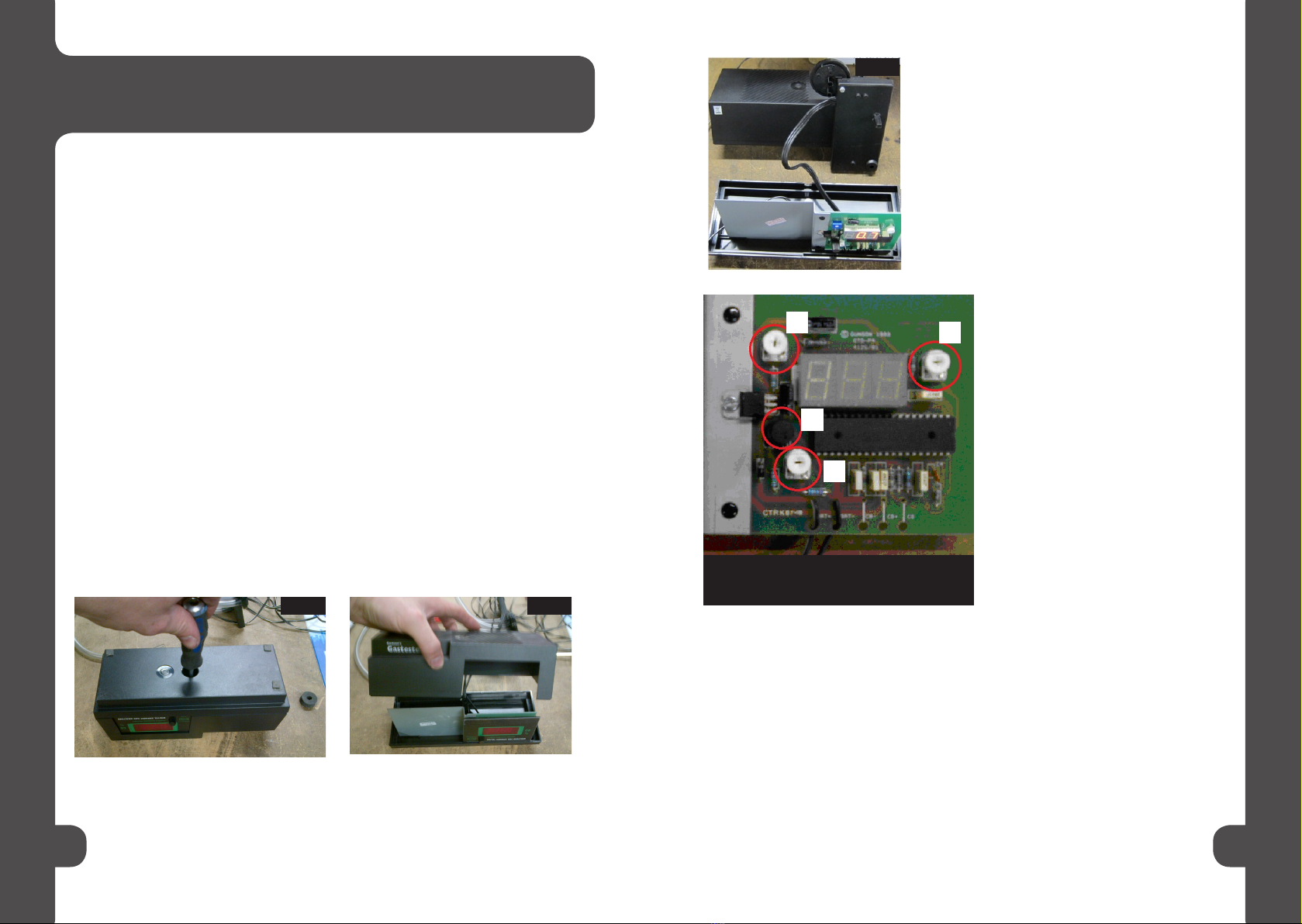
1. Disconnect the Gastester from its power source and turn the upside down. Remove the
central fixing screw as shown in Fig. 1.
2. Place the Gastester back on its base and remove the top as shown in Fig. 2.
3. Remove the front panel to gain access to the adjustment controls as shown in Fig. 3.
Fig. 1. Fig. 2.
Fig. 3. Warning: do not touch or adjust controls A and B.
4. Connect up the Gastester and allow the reading
to stabilise. Allow the tool to fully warm up for a
minimum of 5 minutes.
NB: During the adjustment process ensure the
pump unit and circuit board remain still and vertical
as shown in Fig. 3.
This completes the calibration process for the Gastester.
Disconnect the power cables and put the casing back together in reverse order.
Reconnect and follow the instructions for use including adjusting the display to 2.0%
after the initial warm up period.
Note: 2.0% is the background level for CO2 in the atmosphere.
The above process calibrates only when the reading is stable. If the reading
continually fluctuates the machine will need to be returned to the Tool Connection Ltd
for test and repair.
AB
C
D


