GVA Lighting FL Series User manual

Architectural Spot and Flood Light INSTALLATION GUIDE
Specifications are subject to change without notice. Every effort has been made to ensure that the information provided in this manual is accurate.
GVA Lighting Inc. is not responsible for printing or clerical errors. Refer to www.gvalighting.com for additional information.
FL Series F L10 0 ™
FL 20 0 ™
FL50 ™
FL2 5 ™
GVA Lighting, Inc. 2771 Bristol Cir, Oakville, ON L6H 6X5
IG, FL SERIES, 2021-03-31 | Page 1 / 12
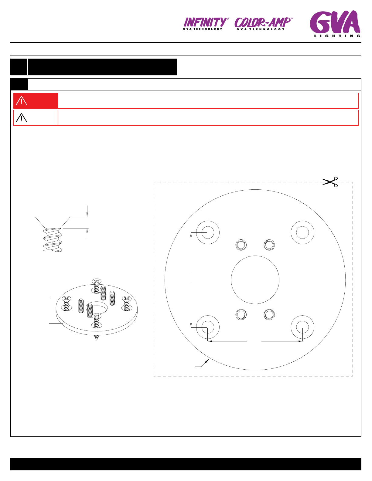
WARNING CAUTION
Do not attempt to install or use Luminaire(s) until you have read and
understand this guide and all safety labels.
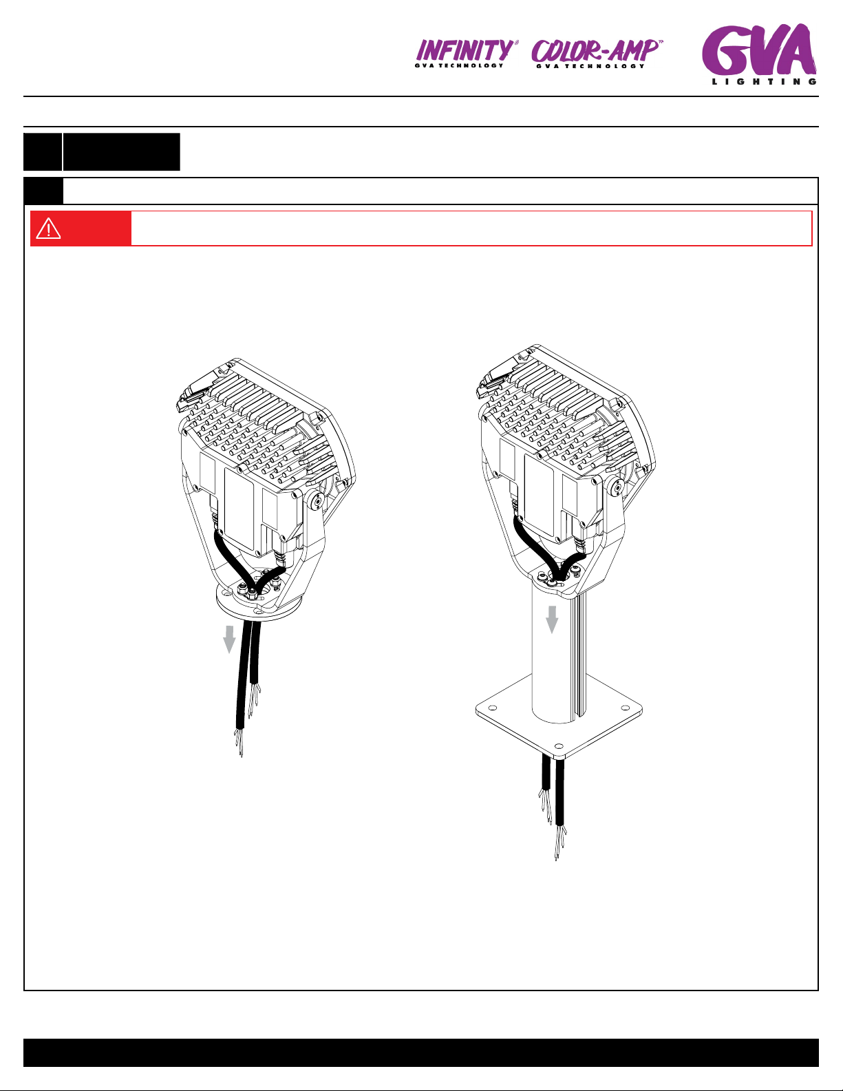
Luminaire(s) must be installed by a qualified professional.
Luminaire(s) must be installed in accordance with all national and
local electrical and construction regulations.
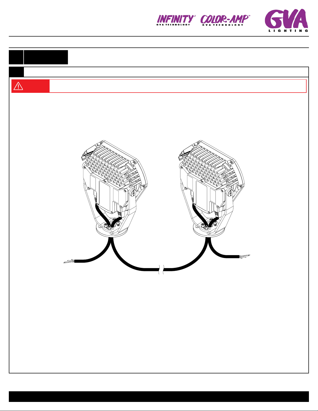
Ensure that main power supply is OFF before installing or wiring
luminaire(s).
Do not exceed specified voltage and current input.
Do not use luminaire(s) with a damaged lens, body, or cable.
Failing to install luminaire(s) according to warnings may result in
a hazardous situation which can cause equipment and property
damage, personal injury, or death.
Do not exceed the maximum number of specified luminaires in a light
run. Doing so will result in a current overload.
GVA Luminaires have no serviceable parts. Do not attempt to open
the units.
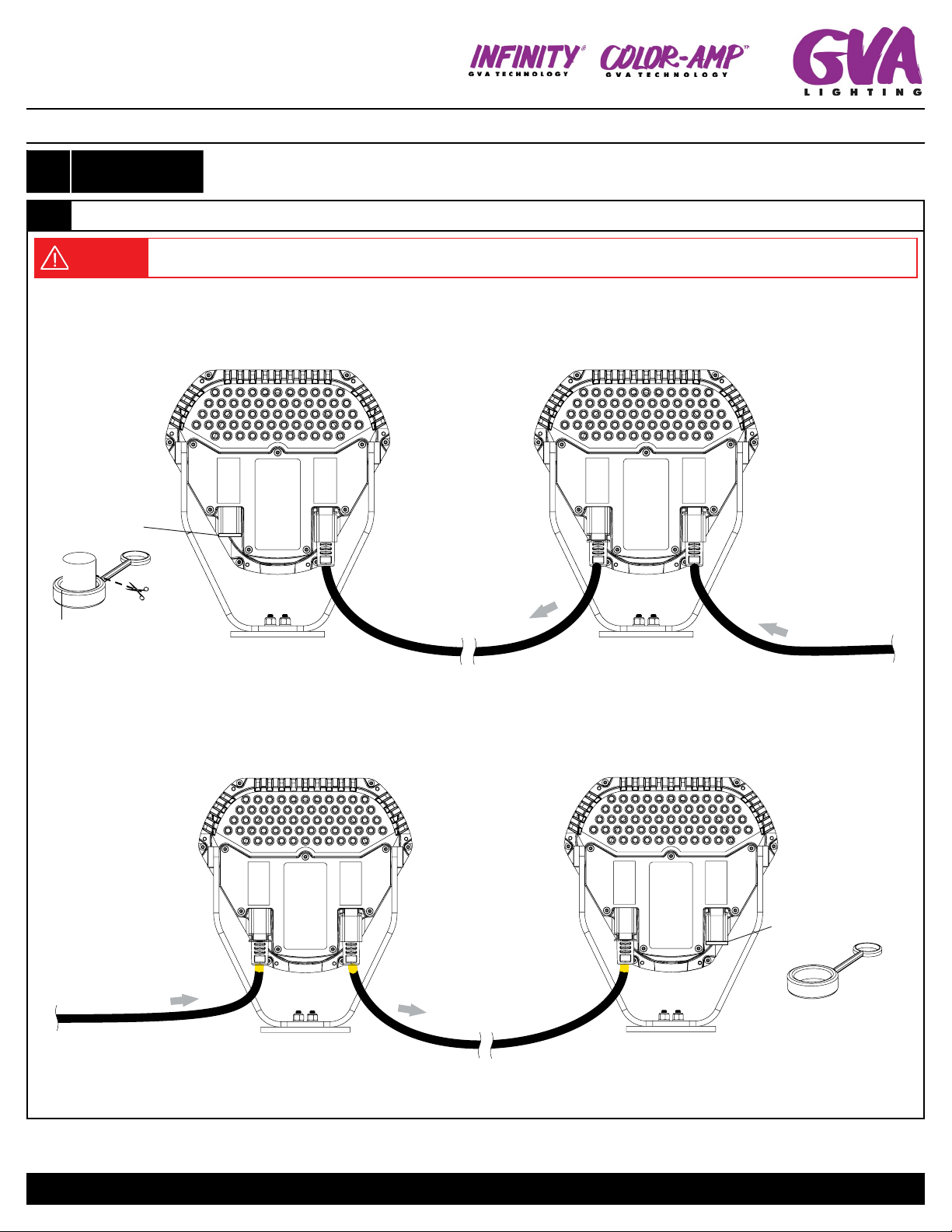
Do not hot swap. Ensure power supply is off before connecting or
disconnecting fixtures.
Do not stare into beam or view directly with optical instruments.
Unauthorized feild repairs will void warranty.

Architectural Spot and Flood Light INSTALLATION GUIDE
Specifications are subject to change without notice. Every effort has been made to ensure that the information provided in this manual is accurate.
GVA Lighting Inc. is not responsible for printing or clerical errors. Refer to www.gvalighting.com for additional information.
FL Series F L10 0 ™
FL 20 0 ™
FL50 ™
FL2 5 ™
GVA Lighting, Inc. 2771 Bristol Cir, Oakville, ON L6H 6X5
IG, FL SERIES, 2021-03-31 | Page 2 / 12
1LUMINAIRE
INSTALLATION
1.1 MOUNTING PLATE
WARNING Use mounting hardware suitable for the mounting surface. Use of innappropriate hardware may result in dismounting of
the bracket and can result in equipment damage, injuries, or death.
CAUTION Failure to select the appropriate hardware may result in the screw heads not being flush with the mounting profile which
will hinder the installation of the fixture.
1.1.A SM Mounting Plate
NOTE: If installing SM HD Mounting Plate refer to Step 1.1.B.
Install mounting plate using M6 Or 1/4" Flathead Screws (supplied by others) suitable for the mounting surface. Refer to "SM MOUNTING
HOLE TEMPLATE" to mark holes prior to installation, if necessary.
SM MOUNTING
HOLE TEMPLATE
(1:1 SCALE)
NOTE: GVA Lighting cannot guarentee that this installation guide is printed to scale. Measure template to
ensure that it is 1:1 scale.
SM MOUNTING
PLATE
(supplied)
M6 Or 1/4"
SCREW
(supplied by others)
3.6mm
0.14in
Max.
REQUIRED HARDWARE:
M6 Or 1/4"
FLATHEAD SCREW
(supplied by others)
4X
Ø 105mm
4.13in
55mm
2.17in
55mm
2.17in

Architectural Spot and Flood Light INSTALLATION GUIDE
Specifications are subject to change without notice. Every effort has been made to ensure that the information provided in this manual is accurate.
GVA Lighting Inc. is not responsible for printing or clerical errors. Refer to www.gvalighting.com for additional information.
FL Series F L10 0 ™
FL 20 0 ™
FL50 ™
FL2 5 ™
GVA Lighting, Inc. 2771 Bristol Cir, Oakville, ON L6H 6X5
IG, FL SERIES, 2021-03-31 | Page 3 / 12
1.1 MOUNTING PLATE CONTINUED
1.1.B SM HD Mounting Plate
NOTE: If installing SM Mounting Plate refer to Step 1.1.A.
Install mounting plate in desired location using M9 or 3/8" Screw or Bolt (supplied by others) suitable for the mounting surface. Refer to "SM
HD MOUNTING HOLE TEMPLATE" to mark holes prior to installation, if necessary.
SM HD MOUNTING
HOLE TEMPLATE
(1:1 SCALE)
M9 OR 3/8"
SCREW OR BOLT
(supplied by others)
REQUIRED HARDWARE:
4X
SM HD MOUNTING
PLATE
(supplied)
M9 or 3/8"
SCREW OR BOLT
(supplied by others)
NOTE: GVA Lighting cannot guarentee that this installation guide is printed to scale. Measure template to ensure that it is 1:1 scale.
115mm
4.53in
115mm
4.53in
150mm
5.91in
150mm
5.91in

Architectural Spot and Flood Light INSTALLATION GUIDE
Specifications are subject to change without notice. Every effort has been made to ensure that the information provided in this manual is accurate.
GVA Lighting Inc. is not responsible for printing or clerical errors. Refer to www.gvalighting.com for additional information.
FL Series F L10 0 ™
FL 20 0 ™
FL50 ™
FL2 5 ™
GVA Lighting, Inc. 2771 Bristol Cir, Oakville, ON L6H 6X5
IG, FL SERIES, 2021-03-31 | Page 4 / 12
1.1 MOUNTING PLATE CONTINUED
1.1.B SM HD Mounting Plate
NOTE: If installing SM Mounting Plate refer to Step 1.1.A.
SM HD MOUNTING
HOLE TEMPLATE
(1:1 SCALE)
M9 OR 3/8"
SCREW OR BOLT
(supplied by others)
REQUIRED HARDWARE:
4X
SM HD MOUNTING
PLATE
(supplied)
M9 or 3/8"
SCREW OR BOLT
(supplied by others)
NOTE: GVA Lighting cannot guarentee that this installation guide is printed to scale. Measure template to ensure that it is 1:1 scale.
115mm
4.53in
115mm
4.53in
150mm
5.91in
150mm
5.91in

Architectural Spot and Flood Light INSTALLATION GUIDE
Specifications are subject to change without notice. Every effort has been made to ensure that the information provided in this manual is accurate.
GVA Lighting Inc. is not responsible for printing or clerical errors. Refer to www.gvalighting.com for additional information.
FL Series F L10 0 ™
FL 20 0 ™
FL50 ™
FL2 5 ™
GVA Lighting, Inc. 2771 Bristol Cir, Oakville, ON L6H 6X5
IG, FL SERIES, 2021-03-31 | Page 5 / 12
1.2 MOUNTING BRACKET
1.2.A Surface Mount (SM200) Bracket
Be advised that the mounting plate must be installed onto the mounting surface before the FL bracket can be installed onto the mounting plate.
At this stage, plan to orient the mounting plate so that the fixture will be pointing in the intended direction once installed. Once the mounting
plate is installed, use the provided adjustment hardware to install the FL bracket to the mounting plate and adjust the direction that the fixture is
pointing as required. Torque the 4X locking nuts (242152) to 10Nm (7.4ft-lb).
241810
NO.14 FLAT WASHER
(supplied)
242152
NYLON LOCKING NUT
1/4"-20
(supplied)
4X
ADJUSTMENT HARDWARE
4X
NOTE: Mounting plate can be oriented in 90° increments so that the fixture will be
pointing in the intended general direction once installed.
ADJUST DIRECTION
USING ADJUSTMENT
HARDWARE
242152
241810
Mounting Hardware
(Supplied by others)
Mounting Plate
*FL50™shown in diagram.

Architectural Spot and Flood Light INSTALLATION GUIDE
Specifications are subject to change without notice. Every effort has been made to ensure that the information provided in this manual is accurate.
GVA Lighting Inc. is not responsible for printing or clerical errors. Refer to www.gvalighting.com for additional information.
FL Series F L10 0 ™
FL 20 0 ™
FL50 ™
FL2 5 ™
GVA Lighting, Inc. 2771 Bristol Cir, Oakville, ON L6H 6X5
IG, FL SERIES, 2021-03-31 | Page 6 / 12
1.2 MOUNTING BRACKET
1.2.B Surface Mount Heavy Duty (SM HD) Bracket
Be advised that the mounting pole must be installed onto the mounting plate with 4X screws (242982) using the security allen key (241620)
before the mounting plate can be installed onto the mounting surface. At this stage, plan to orient the mounting plate so that the fixture will
be pointing in the intended direction once installed. Once the mounting plate is installed, use the provided adjustment hardware and security
allen key (241620) to install the FL bracket to the mounting pole and adjust the direction that the fixture is pointing as required. Torque the 8X
screws (242982 and 242983) to 10Nm (7.4ft-lb).
242982
FLAT HEAD SCREW
1/4"-20X0.625
241810
NO.14 FLAT WASHER
(supplied)
241620
SECURITY ALLEN KEY
(supplied)
4X
REQUIRED HARDWARE:
242983
BUTTON HEAD
SECURITY SCREW
1/4"-20X0.75
4X4X 1X
*FL50™shown
in diagram.
Mounting Hardware
(Supplied by others)
242983
Mounting Plate
Mounting Pole
242982
NOTE: Mounting plate can be oriented in 90°
increments so that the fixture will be pointing
in the intended general direction once
installed.
241810
ADJUST DIRECTION
USING ADJUSTMENT
HARDWARE

Architectural Spot and Flood Light INSTALLATION GUIDE
Specifications are subject to change without notice. Every effort has been made to ensure that the information provided in this manual is accurate.
GVA Lighting Inc. is not responsible for printing or clerical errors. Refer to www.gvalighting.com for additional information.
FL Series F L10 0 ™
FL 20 0 ™
FL50 ™
FL2 5 ™
GVA Lighting, Inc. 2771 Bristol Cir, Oakville, ON L6H 6X5
IG, FL SERIES, 2021-03-31 | Page 7 / 12
1.3 ADJUSTMENT SET SCREWS
1.3.A Fixture adjustment set screws
Adjust the aim of the fixture and then lock the rotation with 4X set screws using the allen key (241622).Torque each set screw to 3Nm (2.2ft-lb).
REQUIRED HARDWARE:
241622
ALLEN KEY
(supplied)
1X
ADJUST DIRECTION
BEFORE LOCKING
THE SET SCREWS
ENGAGE SET
SCREWS ON
BOTH SIDES TO
LOCK ROTATION
ADJUST DIRECTION
BEFORE LOCKING
THE SET SCREWS

Architectural Spot and Flood Light INSTALLATION GUIDE
Specifications are subject to change without notice. Every effort has been made to ensure that the information provided in this manual is accurate.
GVA Lighting Inc. is not responsible for printing or clerical errors. Refer to www.gvalighting.com for additional information.
FL Series F L10 0 ™
FL 20 0 ™
FL50 ™
FL2 5 ™
GVA Lighting, Inc. 2771 Bristol Cir, Oakville, ON L6H 6X5
IG, FL SERIES, 2021-03-31 | Page 8 / 12
2FIXTURE
CONNECTIONS
2.1 INPUT AND OUTPUT FIXTURE CONNECTIONS
WARNING Ensure power supply is turned OFF before making any connections. Connecting the luminaire while the power is turned
ON may result in equipment damage.
Once the bracket has been fastened to the mounting plate, connect the input and output jumper cables and/or leader cables to the fixture. The
connector will make an audible ‘CLICK’ when inserted correctly. Add a dust cap at the end of each run.
2.1.A INF and AC Fixture Connections
INF IP67 DUST CAP
(must be used at the
end of each run)
remove the tail from the
dust cap before installation
LUMINAIRE
LEADER CABLE
(Power-Data from
power supply)
INPUT
CONNECTION
INPUT
CONNECTION
OUTPUT
CONNECTION
LUMINAIRE
JUMPER CABLE
*FL50™ shown in diagram.
2.1.B ELV Fixture Connections
LUMINAIRE
LEADER CABLE
(Power-Data from
power supply) LUMINAIRE
JUMPER CABLE
INPUT
CONNECTION
INPUT
CONNECTION
OUTPUT
CONNECTION
ELV IP67 DUST CAP
(must be used at the
end of each run)
*FL50™ shown in diagram.

Architectural Spot and Flood Light INSTALLATION GUIDE
Specifications are subject to change without notice. Every effort has been made to ensure that the information provided in this manual is accurate.
GVA Lighting Inc. is not responsible for printing or clerical errors. Refer to www.gvalighting.com for additional information.
FL Series F L10 0 ™
FL 20 0 ™
FL50 ™
FL2 5 ™
GVA Lighting, Inc. 2771 Bristol Cir, Oakville, ON L6H 6X5
IG, FL SERIES, 2021-03-31 | Page 9 / 12
3CABLE
MANAGEMENT
3.1 INPUT AND OUTPUT FIXTURE CONNECTIONS
WARNING Ensure power supply is turned OFF before making any connections. Connecting the luminaire while the power is turned
ON may result in equipment damage.
3.1.A Leader Cables
Optional: leader cables may be fed through the bracket so that connections can be made on the other side of the mounting surface using a
junction box or cable joiner.
*FL50™ shown in diagram.

Architectural Spot and Flood Light INSTALLATION GUIDE
Specifications are subject to change without notice. Every effort has been made to ensure that the information provided in this manual is accurate.
GVA Lighting Inc. is not responsible for printing or clerical errors. Refer to www.gvalighting.com for additional information.
FL Series F L10 0 ™
FL 20 0 ™
FL50 ™
FL2 5 ™
GVA Lighting, Inc. 2771 Bristol Cir, Oakville, ON L6H 6X5
IG, FL SERIES, 2021-03-31 | Page 10 / 12
3CABLE
MANAGEMENT
3.1 INPUT AND OUTPUT FIXTURE CONNECTIONS
WARNING Ensure power supply is turned OFF before making any connections. Connecting the luminaire while the power is turned
ON may result in equipment damage.
3.1.B Jumper Cables
Optional: A jumper cable may be fed through the brackets to connect the output side of one fixture to the input side of the next. The input side
of the first fixture and output side of the second must be connected through leader cables if they are to be fed through the brackets.
*FL50™ shown in diagram.
LUMINAIRE
JUMPER CABLE

Architectural Spot and Flood Light INSTALLATION GUIDE
Specifications are subject to change without notice. Every effort has been made to ensure that the information provided in this manual is accurate.
GVA Lighting Inc. is not responsible for printing or clerical errors. Refer to www.gvalighting.com for additional information.
FL Series F L10 0 ™
FL 20 0 ™
FL50 ™
FL2 5 ™
GVA Lighting, Inc. 2771 Bristol Cir, Oakville, ON L6H 6X5
IG, FL SERIES, 2021-03-31 | Page 11 / 12
4ACCESSORY
INSTALLATION
4.1
NOTE: Accessory installation is optional.
WARNING If fixture is installed in high wind or vibration location, apply Locktite 271 (supplied by others) on moving screws. Failure to
do so may result in equipment damage, serious injury or death.
Up to three barndoor or visor accessories can be installed onto one FL Series fixture. Line the holes on the back of the fixture up to the holes
on the accessory. Use the supplied hardware to attach the accessory to the fixture.
*FL50™shown
in diagram.
241603
FLAT WASHER
(per accessory/ supplied)
2X
REQUIRED HARDWARE:
240776
M4 SCREW
(per accessory/ supplied)
2X
VISOR
BARNDOOR
*FL50™shown
in diagram.
NOTE: If the barndoor
mechanism is too
loose, tighten the cap
screw and locknut up
to desired preset.

Architectural Spot and Flood Light INSTALLATION GUIDE
Specifications are subject to change without notice. Every effort has been made to ensure that the information provided in this manual is accurate.
GVA Lighting Inc. is not responsible for printing or clerical errors. Refer to www.gvalighting.com for additional information.
FL Series F L10 0 ™
FL 20 0 ™
FL50 ™
FL2 5 ™
GVA Lighting, Inc. 2771 Bristol Cir, Oakville, ON L6H 6X5
IG, FL SERIES, 2021-03-31 | Page 12 / 12
NOTES
Other manuals for FL Series
1
This manual suits for next models
4
Table of contents
Other GVA Lighting Lighting Equipment manuals
Popular Lighting Equipment manuals by other brands

Finelite
Finelite HP-6 Recessed Flush Diffuser Tech Zone 6"... installation instructions

DTS
DTS Raptor user manual

Ledra Brands
Ledra Brands ALPHABET NU3RD installation instructions

JLG
JLG METRO-MH Operation and safety manual

Inspire
Inspire Olga Assembly, Use, Maintenance Manual

EuroLite
EuroLite BLACK GUN E-40 user manual