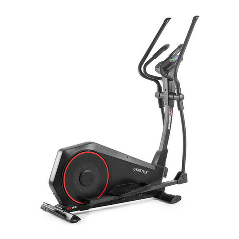
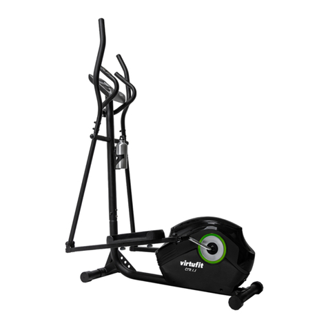
Gymstick GX8.0 User manual

GX8.0 CROSSTRAINER
USER MANUAL
IMPORTANT: Read all instructions carefully before using this product. Retain this owner’s manual for future
reference. The specications of this product may vary from this photo, subject to change without notice.

2GX8.0 CROSSTRAINER
BEFORE YOU BEGIN
Thank you for choosing the Gymstick GX8.0 Crosstrainer. We take great pride in producing this
quality product and hope it will provide many hours of eective exercise to make you feel better,
look better and enjoy life to its fullest.
TABLE OF CONTENT
1. SAFETY INSTRUCTIONS ................................................................................................ 3
2. EXPLODED DRAWING...................................................................................................... 4
3. PARTS LIST........................................................................................................................ 6
4. HARDWARE PACKING LIST.............................................................................................. 8
5. ASSEMBLY INSTRUCTION................................................................................................ 9
6. COMPUTER OPERATION INSTRUCTIONS...................................................................... 15
7. MAINTENANCE.................................................................................................................. 19
8 TROUBLESHOOT............................................................................................................... 19
9. WARM UP AND COOL DOWN ROUTINE.......................................................................... 20
10. IMPLIED WARRANTY......................................................................................................... 23
READ AND FOLLOW THE SAFETY INSTRUCTIONS. FAILURE TO FOLLOW THESE INSTRUCTIONS
CAN RESULT IN SERIOUS INJURY.
!
NOTIFICATION!

3GX8.0 CROSSTRAINER
!
WARNING!
SAFETY INSTRUCTIONS
Basic precautions should always be followed, including the following safety instructions when using
this equipment: Read all instructions before using this equipment.
1. Keep children and pets away from the machine at all times. DO NOT leave unattended children in the
same room with the machine.
2. Handicapped or disabled persons should not use the machine without the presence of a qualied health
professional or physician.
3. If the user experiences dizziness, nausea, chest pain, or any other abnormal symptoms, STOP the
workout at once. CONSULT A PHYSICIAN IMMEDIATELY.
4. Before beginning training, remove all within a radius of 2 meters from the machine. DO NOT place any
sharp objects around the device.
5. Position the machine on a clear, level surface away from water and moisture. Place mat under the unit to
help keep the machine stable and to protect the oor.
6. Use the machine only for its intended use as described in this manual. DO NOT use any other
accessories not recommended by the manufacturer.
7. Assemble the machine exactly as the descriptions in the instruction manual.
8. Check all bolts and other connections before using the machine for the rst time and ensure that the
trainer is in the safe condition.
9. Hold a routine inspection of the equipment. Pay special attention to components which are the most
susceptible to wear o, i.e. connecting points and wheels. The defective components should be replaced
immediately. The safety level of this equipment can only be maintained by doing so.
10. NEVER operate the machine if it is not functioning properly.
11. This machine can be used for only one person’s training at a time.
12. Do not use abrasive cleaning articles to clean the machine. Remove drops of sweat from the machine
immediately after nishing training.
13. Always wear appropriate workout clothing when exercising. Running or aerobic shoes are also required.
14. Before exercising, always do warm-up and stretching rst.
15. The maximum weight capacity for this product is 130kgs.
BEFORE BEGINNING THIS OR ANY EXERCISE PROGRAM, CONSULT YOUR PHYSICIAN FIRST.
THIS IS ESPECIALLY IMPORTANT FOR INDIVIDUALS OVER THE AGE OF 35 OR PERSONS WITH
PRE-EXISTING HEALTH PROBLEMS.

4GX8.0 CROSSTRAINER
EXPLODED DRAWING

5GX8.0 CROSSTRAINER
EXPLODED DRAWING

6GX8.0 CROSSTRAINER
PARTS LIST
No. Description Qty
001 Main Frame 1
002 Front Post 1
003 Left Swing Tube 1
004 Right Swing Tube 1
005 Left Foot Tube 1
006 Right Foot Tube 1
007(L/R) Drive Tube 2
008 Rear Main Frame 1
009 Front Stabilized 1
010 Left Handrail Arm 1
011 Right Handrail Arm 1
012 Handlebar 1
013 Computer 1
014 Bolt M5*10 8
015 Handlebar Foam Grip Ø24*
Ø31*510
2
016 End Cap for Handlebar
Ø25*1.5
2
017 Hand Pulse Sensor with
WireL=750mm
2
018 Self- tapping screw ST4.2*20 2
019 Big Washer Ø8* Ø20*2.0 8
020 Arc Washer Ø8* Ø16*1.5 4
021 Extension Sensor
WireL=800mm
1
022 Front Post Cover 1
023 Bolt M8*16 12
024 Connecting rod small bushing
Ø18* Ø8*10
4
025 End Cap for Handlebar Ø50 2
026 Handlebar Foam Grip
Ø31*Ø37*700
2
027 Bushing 2
028 Bolt M8*49 4
No. Description Qty
029 Cap Nut M8 8
030 Cap Nut Ø38 2
031 Bolt M8*20 19
032 Spring Washer Ø8 14
033 Washer Ø8* Ø33*2.0 2
034 Big Washer Ø19* Ø38*3.0 4
035 POM Bushing Ф27*11 16
036 Plastic Bushing Ø38x24 16
037 Wave Spring Washer Ø19*
Ø29*0.5
2
038 Shaft Sleeve 2
039 Sensor Wire L=600mm 1
040 Nut M8 5
041 Washers Ø8* Ø16*1.5 2
042 Bolt M8*75 2
043 Big Wave Washer Ø8* Ø20*2.0 4
044 Foot Pad M10*20 6
045 Nut M10 6
046 Circular Tube Plug Ø60*1.5 6
047 Bolt Ø8*32 2
048 Bearing608 4
049 Roller wheel Ø71*24 2
050 Bolt M6*12 2
051 Bolt M8*80 2
052 Self-tapping self-drilling screw
ST4.2*20
12
053 Aluminium Bar 530*42*2.1 2
054 Big Washers Ø8* Ø25*2.0 14
055 Left Foot Pedal 1
056 Right foot Pedal 1

7GX8.0 CROSSTRAINER
PARTS LIST
No. Description Qty
057 Pedal connecting shaft Ø19*
82.5
2
058 Left Roller cover 2
059 Right Roller cover 2
060 Roller connecting shaft Ø15*
63.8
2
061 Roller Spacing Ø22* 3.1 4
062 Bearing 6202 4
063 Pulley 2
064 Foot Turn Tube Assembly 2
065 Nut Cap S13 2
066 Bolt M8*50 2
067 End Cap Ø38*1.8 4
068 Connecting rod shaft Ø19*61 2
069 Self- tapping screw ST2.9*16 4
070 Left Swing Tube Cover-A 1
071 Left Swing Tube Cover-B 1
072 Right Swing Tube Cover-A 1
073 Right Swing Tube Cover-B 1
074 Eyebolt M8*65 1
075 Idle Wheel Bracket 1
076 Press Wheel 1
077 Washer Ø12* Ø6*1.0 1
078 Bolt M6*12 1
079 Spring Washer Ø6 6
080 Circlip Ø20*1.0 2
081 Wave Washer Ø20* Ø24*0.3 1
082 Bearing 6004-2Z 2
083 Bolt M6*15 4
No. Description Qty
084 Nut M6 4
085 Belt Pulley 1
086 Straight Spindle Assembly 1
087 Belt 1
088 Plastic BoltΦ8x32 2
089 Left Cain Cover 1
090 Right Cain Cover 1
091 Nut M10x1.25 2
092 Turntable Assembly 2
093 Screw ST4.2*25 6
094 Turntable 2
095 Flywheel 1
096 Eyebolt M6*36 2
097 U-bracket 31*30*δ1.0 2
098 Bolt M6 S10 2
099 Nut M10*1.0*6 2
100 Nut M10*1 3
101 Limit File Piece 4
102 Motor L=300 1
103 Motor is disconnected L=400 1
104 AC adaptor 1
105 Hexagonal at nut for connecting
wire
1
106 Voltage regulator terminal 1
107 Sensor with Wire L=750mm 1
108 Screw ST2.9*12 2
109 End Cup for Turntable 2

8GX8.0 CROSSTRAINER
HARDWARE PACKING LIST

9GX8.0 CROSSTRAINER
ASSEMBLY INSTRUCTION
STEP 1. Foot Pad Installation
Position Four Adjustment Foot Pad(44) onto the Rear Main Frame(8)
Position Two Adjustment Foot Pad(44) onto the Front Stabilized(9)
STEP 2. Front Stabilized and Rear Main Frame Installation
Attach the Rear Main Frame (8) onto the Main Frame (1) with
• two M8*80 Bolts (51)
• two Ø8* Ø20*2.0 Big Wave Washers (43)
• two Ø8 Spring Washers (32)
• two M8 Cap Nuts (29)
Attach the Front Stabilized (9) onto the Main Frame (1) with
• two M8*75 Bolts (42)
• two Ø8* Ø20*2.0 Big Wave Washers (43)
• two Ø8 Spring Washers (32)
• two M8 Cap Nuts (29)

10GX8.0 CROSSTRAINER
ASSEMBLY INSTRUCTION
STEP 3. Front Post and Tension Control Knob
Installation
Remove six Bolts M8*20 (31), six Spring
Washers Ø8(32), six Big Washers Ø8* Ø20*2.0
(19) from the Main Frame (1). Slide the Front
Post Cover (22) onto the tube of the Front Post
(2).
Connect the Sensor Wire (39) from the Main
Frame (1) with the Sensor Wire (21) from the
Front Post (2).
Attach the Front Post (2) onto the Main Frame
(1) with six Bolts M8*20 (31) ,six Spring Washers
Ø8(32), six Big Washers Ø8* Ø20*2.0 (19) that
were removed .
STEP 4. Left/Right Swing Tube Installation
Remove two Bolt M8*20(31), two Spring Washers Ø8(32), two big washers Ø19* Ø38*3.0(34), two
Ø19* Ø29*0.5 Wave Spring Washers(37) and two Ø8*Ø25*2.0 Big Washers(54) from Front Post(2).
Please note: coat the Front Post with Grease.
Attach the Left Swing Tube (3) onto the
Front Post (2) with one Bolt M8*20 (31),
one Spring Washer Ø8(32), one big
washer Ø19* Ø38*3.0(34), one Ø19*
Ø29*0.5 Wave Spring Washer(37) and
one Ø8* Ø25*2.0 Big Washer(54) that
were removed.
Attach the Right Swing Tube (4) onto
the Front Post (2) with one Bolt M8*20
(31), one Spring Washer Ø8(32), one
big washer Ø19* Ø38*3.0(34), one Ø19*
Ø29*0.5 Wave Spring Washer(37) and
one Ø8* Ø25*2.0 Big Washer(54) that
were removed.

11GX8.0 CROSSTRAINER
ASSEMBLY INSTRUCTION
STEP 5. Drive Tube Installation
Remove one Nut M8 (40) ,one Washer Ø8*
Ø16*1.5 (41), one Bolt M8*50 (66) from the
Foot Turn Tube Assembly (64).
Attach the Left Drive Tube(7) on the Left
Foot Tube (5) with one Nut M8 (40), one
Washer Ø8* Ø16*1.5 (41), one Bolt M8*50
(66) that were removed.
Cover a Cap Nut S13(65) onto the Left
Drive Tube(7).
Repeat above step to the Right Foot Tube
(6) on the Right Drive Tube(7) and Cover a
Cap Nut S13(65).
STEP 6. Left/ Right Foot Tube Installation
Remove two Bolts M8*16(23), two Spring Washers Ø8* Ø25*2.0 (54), one Connecting rod shaft
Ø19*61 (68)from the Left Foot Tube (5).
Please note: coat the Connecting rod shaft Ø19*61 (68) with Grease.
Attach the Left Foot Tube (5) on the Left Swing Tube (3) with two Bolts M8*16(23), two Spring
Washers Ø8* Ø25*2.0 (54), one Connecting rod shaft Ø19*61 (68) that were removed.
Note: Aim the Connecting rod shaft(68) in
the direction of the notch.
Repeat above step to the Right Foot Tube (6)
on the Right Swing Tube (4).

12GX8.0 CROSSTRAINER
ASSEMBLY INSTRUCTION
STEP 7. Left/Right Foot Pedal and Left/Right Roller cover Installation
Remove four Screw M5*10 (14) from the Drive Tube (7).
Attach two sets of Left/Right Roller covers (58/59) onto two Drive Tube(7) with four Screw
M5*10(14) that were removed.
Remove three Screws M8*20 (31) from the
Left Foot Tube (5).
Attach the Left Foot Pedal (55) onto the Left
Foot Tube (5) with three M8*20 Bolts (31)
that were removed.
Remove three M8*20 Bolts (31) from the
Right Foot Tube (6).
Attach the Right Foot Pedal (56) onto the
Right Foot Tube (6) with three M8*20 Bolts
(31) that were removed.
STEP 8. Handrail Arm Installation
Attach the Left Handrail Arm (10)onto the Left
Swing Tube(3) with two Bolts M8*49(28), two
Cruve Washers Ø8* Ø16*1.5(20), and Cap
Nut M8(29).
Attach the Right Handrail Arm (11) onto
the Right Swing Tube(4) with two Bolts
M8*49(28), two Cruve Washers Ø8*
Ø16*1.5(20), and Cap Nut M8(29).

13GX8.0 CROSSTRAINER
ASSEMBLY INSTRUCTION
STEP 9. Left /Right Handrail Arm Cover
Installation
Attach the Left Swing Tube Cover A /B
(70/71) onto the Left Handrail Arm (10)
with two Self-tapping self-drilling screws
ST4.2*20 (52) and two Self-Tapping
Driling Screws ST2.9*16(69).
Attach the Right Swing Tube Cover A /B
(72/73) onto the Right Handrail Arm(11)
with two Self-tapping self-drilling screws
ST4.2*20 (52) and two Self-Tapping
Drilling Screws ST2.9*16(69).
STEP 10. Handlebar Installation
Remove two M8*20 Bolts (31) and two
Cruve Washers Ø8* Ø20*2.0(19) from the
Front Post (2).
Insert the Hand Pulse Sensor Wires
(17) through into the bottom hole of the
Handlebar (12) and pull it out from the
square hole of the Handlebar (12).
Attach the Handlebar (12) onto the Front
Post (2) with two M8*20 Bolts (31) and
two Cruve Washers Ø8* Ø16*1.5(19) that
were removed.

14GX8.0 CROSSTRAINER
STEP 11. Computer Installation
Remove four M5x10 Bolts (14) from the back
of the Computer (13).
Connect the Sensor Wire (21) and Hand Pulse
Sensor Wires (17) to the wires that come
from the Computer (13) and then attach the
Computer (13) onto the top end of the Front
Post (2) with four M5x10 Bolts (14) that were
removed.
Please note: coat the Aluminum Rod with
PTFE Lubric.
STEP 12. AC Adapter Installation
Plug one end of the AC Adapter(104) into the
power jack of the Power Supply Wire(106) onto
the back of the Left Shroud. Before plugging in,
make sure to check carefully the specications
on the Adapter. Plug the other end of the AC
Adapter(104)into the electrical wall outlet.
ASSEMBLY INSTRUCTION

15GX8.0 CROSSTRAINER
COMPUTER OPERATION INSTRUCTIONS
KEY FUNCTIONS
START/STOP(ST/SP): 1. Starts and Pauses workouts
2. Start body fat measurement
DOWN: Decrease value of selected workout parameter: TIME, DISTANCE, etc.
During the workout it will decrease the resistance load
UP: Increases value of selected workout parameter.
During the workout, it will increase the resistance load.
MODE (ENTER): 1. To input desired value or workout mode.
2. Press to switch display form RPM to SPEED, ODO to DIST,
WATT to Calories during workout.
TEST (PULSE-RECOVERY): Press to enter into Recovery function when computer has the heart rate value.
Recovery is Fitness Level 1-6 after 1 minute. F1 is the best, F6 is the worst.
RESET: To reset current setting. Holding the key for 3 seconds will reset all function
values to zero.
BODY FAT: Quickly select the BODY FAT program.
WORKOUT SELECTION
After power-up using UP or DOWN keys to select then pressing ENTER to enter the desired mode.
SETTING WORKOUT PARAMETERS
After selecting your desired program, you may pre-set several workout parameters for desired results.
WORKOUT PARAMETERS: TIME / DISTANCE / CALORIES /AGE
Note: Some parameters are not adjustable in certain programs.
Once a program has been selected, pressing ENTER, will make “TIME” parameter ash. Using UP OR DOWN KEY
you may select desired time value. Press ENTER KEY to input value. Flashing prompt will move to the next parameter.
Continue use of UP OR DOWN KEY. Press START/STOP to start workout.

16GX8.0 CROSSTRAINER
COMPUTER OPERATION INSTRUCTIONS
MANUAL PROGRAM (P1)
Selecting “MANUAL” using UP OR DOWN KEY then pressing ENTER KEY. First parameter “TIME” will ash so value
can be adjusted using UP OR DOWN KEY. Press ENTER KEY to save value & move to next parameter to be adjusted.
Continue through all desired parameters, pressing START/STOP to start workout.
Note: One of workout parameters counts down to be zero, it will have BEEP-sound and stop the workout automatically.
Press START KEY to continue the workout to reach the unnished workout parameter.
PRE-PROGRAMS (P2-P7)
There are 6 program proles ready for use. Setting Parameters for PRE-PROGRAMS:
Selecting one of pre-programs using UP OR DOWN KEY then pressing ENTER KEY. First parameter “TIME” will ash
so value can be adjusted using UP OR DOWN KEY. Press ENTER KEY to save value & move to next parameter to be
adjusted. Continue through all desired parameters, pressing START/STOP to start workout.
Note: One of workout parameters counts down to be zero, it will have BEEP-sound and stop the workout automatically.
Press START KEY to continue the workout to reach the unnished workout parameter.

17GX8.0 CROSSTRAINER
COMPUTER OPERATION INSTRUCTIONS
HEART RATE CONTROL PROGRAM (P8-P10)
There are 3 selection for target pulse:
P8 - 55% TARGET H.R= 55% of (220-AGE)
P9 - 75% TARGET H.R= 75% of (220-AGE)
P10 - 90% TARGET H.R= 90% of (220-AGE)
Setting Parameters for HEART RATE CONTROL:
Selecting “One of HEART RATE CONTROL PROGRAM” using UP OR DOWN KEY then pressing ENTER KEY.
First parameter “TIME” will ash so value can be adjusted using UP OR DOWN KEY. Press ENTER KEY to save value
& move to next parameter to be adjusted. Continue through all desired parameters, pressing START/STOP to start
workout.
Note: If Pulse is above or below (± 5) the TARGET H.R. computer will adjust the resistance load automatically. It will
check every 10 seconds approx. l resistance load will increase or decrease. One of workout parameters counts down
to be zero, it will have BEEP-sound and stop the workout automatically. Press START/STOP KEY to continue the
workout to reach unnished workout parameter.
TARGET HEART RATE PROGRAM (P11)
Setting Parameters for TARGET H.R.:
Selecting “TARGET H.R.” using UP OR DOWN KEY then pressing ENTER KEY. First parameter “TIME” will ash so
value can be adjusted using UP OR DOWN KEY. Press ENTER KEY to save value & move to next parameter to be
adjusted. Continue through all desired parameters, pressing START/STOP to start workout.
Note: If Pulse is above or below (± 5) the TARGET H.R. computer will adjust the resistance load automatically. It will
check every 10 seconds approx. l resistance load will increase or decrease. One of workout parameters counts down
to be zero, it will have BEEP-sound and stop the workout automatically. Press START/STOP KEY to continue the
workout to reach unnished workout parameter.

18GX8.0 CROSSTRAINER
COMPUTER OPERATION INSTRUCTIONS
BODY FAT PROGRAM (P12)
Setting Parameters for BODY FAT PROGRAM:
Selecting “BODY FAT PROGRAM” using UP OR DOWN KEY then pressing ENTER.
1. “MALE ” will ash so Gender can be adjusted using UP OR DOWN KEY, press ENTER to save gender and move
to next data.
2. “175” of Height will ash so Height can be adjusted using UP OR DOWN KEY, press ENTER KEY save value and
move to next data.
3. “75“ of Weight will ash so Weight can be adjusted using UP OR DOWN KEY, press ENTER KEY to save value
and move to next data.
4. “30” of Age will ash so Age can be adjusted using UP OR DOWN KEY, press ENTER to save value.
Press START/STOP to start measurement, please also grasp hand pulse grips.
After 15 seconds the display will show Body Fat %, BMR, BMI and BODY TYPE.
Note: There are 9 body types divided according to BODY FAT % calculated:
• Type 1 is from 5% to 9%
• Type 2 is from 10% to 14%
• Type 3 is from 15% to 19%
• Type 4 is from 20% to 24%
• Type 5 is from 25% to 29%
• Type 6 is from 30% to 34%
• Type 7 is from 35% to 39%
• Type 8 is from 40% to 44%
• Type 9 is from 45% to 50%
BMR: Basal Metabolism Ratio
BMI: Body Mass Index
CONNECT THE INSTRUMENT POWER SUPPLY
Plug one end of the power adapter into the ac power socket and the output of the other end into the power interface of
the meter. At this time, the meter will emit a “BEEP” sound for 1 second, and the instrument will be fully displayed into
the initial state of the meter.
Li alarm prompt
Instrument display ERROR1 indicates that the connection wire of the motor is not in good contact or the motor is
damaged
Instrument display ERROR2 indicates no handheld heart rate signal input during body fat test
Power supply: power adapter. Input A C (according to national grid standards)

19GX8.0 CROSSTRAINER
MAINTENANCE
CLEANING
The upright bike can be cleaned with a soft cloth and mild detergent. Do not use abrasives or solvents on
plastic parts. Please wipe your perspiration o the upright bike after each use. Be careful not get excessive
moisture on the computer display panel as this might cause an electrical hazard or electronics to fail.
Please keep the upright bike, specially, the computer console, out of direct sunlight to prevent screen
damage. Please inspect all assembly bolts and pedals on the machine for proper tightness every week.
STORAGE
Store the upright bike in a clean and dry environment away from children.
TROUBLESHOOTING
PROBLEM SOLUTION
The elliptical trainer wobbles when in use. Turn the rear stabilizer end cap on the rear
stabilizer as needed to level the elliptical
trainer.
There is no display on the computer
console.
1. Remove the computer console and verify
the wires that come from the computer
console are properly connected to the
wires that come from the front post.
2. Check if the batteries are correctly
positioned and battery springs are in
proper contact with batteries.
3. The batteries in the computer console
may be dead. Change to new batteries.
There is no heart rate reading or heart rate
reading or is erratic / inconsistent.
1. Make sure that the wire connections for
the hand pulse sensors are secure.
2. To ensure the pulse readout is more
precise, please always hold on to the
handlebar grip sensors with two hands
instead of just with one hand only when
you try to test your heart rate gures.
3. Gripping the hand pulse sensors too tight.
Try to maintain moderate pressure while
holding onto the hand pulse sensors.
The elliptical trainer makes a squeaking
noise when in use.
The bolts may be loose on the elliptical trainer,
please inspect the bolts and tighten the loose
bolts.

20GX8.0 CROSSTRAINER
WARM UP AND COOL DOWN ROUTINE
A good exercise program consists of a warm-up, aerobic exercise, and a cool down. Do the entire program
at least two to three times a week, resting for a day between workouts. After several months you can increa-
se your workouts to four or ve times per week.
AEROBIC EXERCISE is any sustained activity that sends oxygen to your muscles via your heart and lungs.
Aerobic exercise improves the tness of your lungs and heart. Aerobic tness is promoted by any activity
that uses your large muscles eg: legs, arms and buttocks. Your heart beats quickly and you breathe deeply.
An aerobic exercise should be part of your entire exercise routine.
The WARM-UP is an important part of any workout. It should begin every session to prepare your body for
more strenuous exercise by heating up and stretching your muscles, increasing your circulation and pulse
rate, and delivering more oxygen to your muscles. ‘
COOL DOWN at the end of your workout, repeat these exercises to reduce soreness in tired muscles.
HEAD ROLLS
Rotate your head to the right for one count, feeling
the stretch up the left side of your neck, then rotate
your head back for one count, stretching your chin
to the ceiling and letting your mouth open. Rotate
your head to the left for one count, then drop your
head to your chest for one count.
SHOULDER LIFTS
Lift your right shoulder toward your ear for one
count. Then lift your left shoulder up for one count
as you lower your right shoulder.
This manual suits for next models
1
Table of contents
Other Gymstick Elliptical Trainer manuals
Popular Elliptical Trainer manuals by other brands

Sunny Health & Fitness
Sunny Health & Fitness Endurance Zone SF-E3804 user manual

Reebok
Reebok Crosstrainer C 5.8e user manual

Spirit
Spirit 161171400 owner's manual

Weslo
Weslo Momentum R 4.2 Elliptical manual

Horizon Fitness
Horizon Fitness ELLIPTICAL RE7.6 Assembly & user's guide

Salter
Salter PT-0098 owner's manual