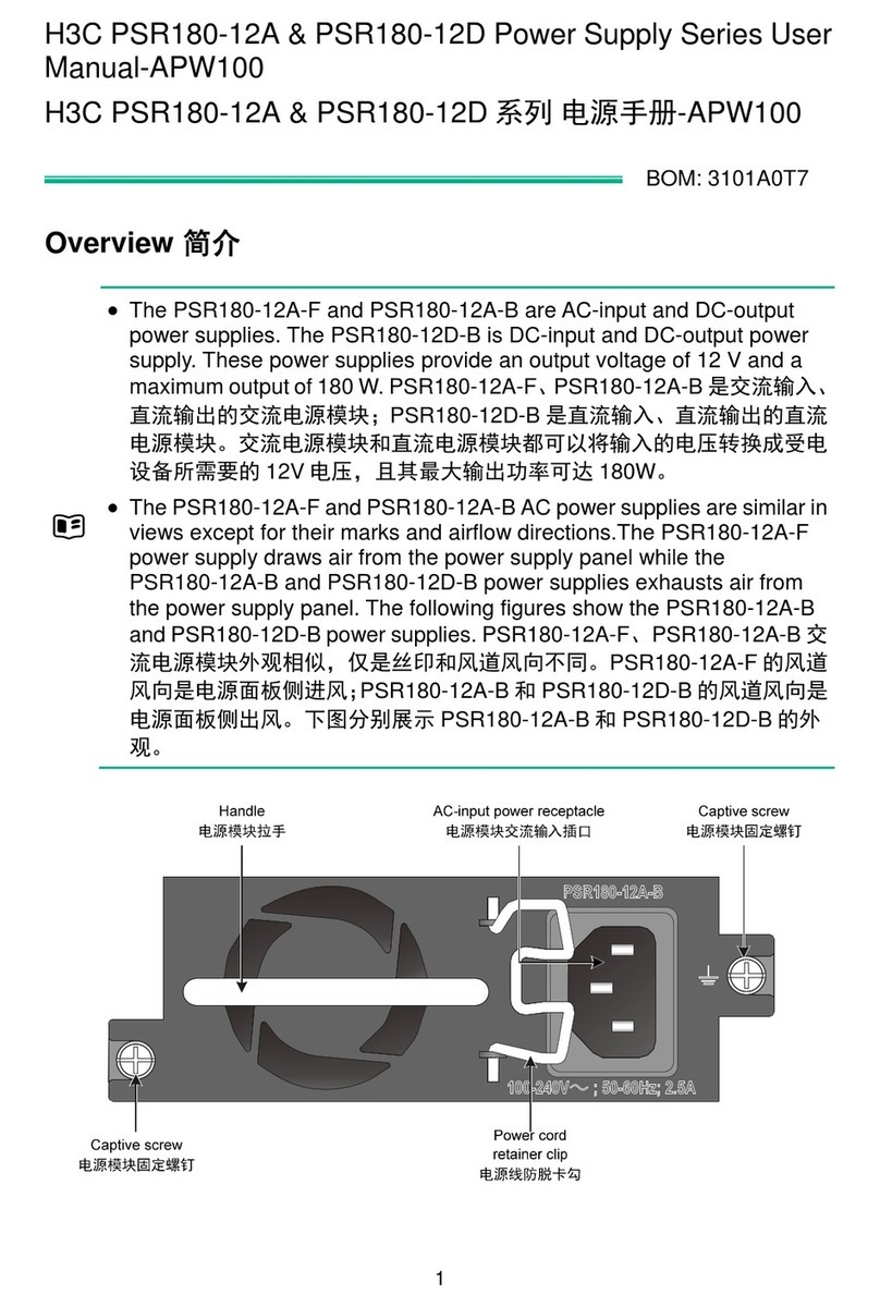
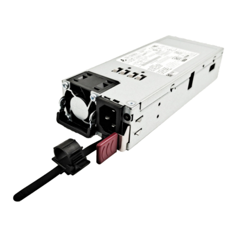
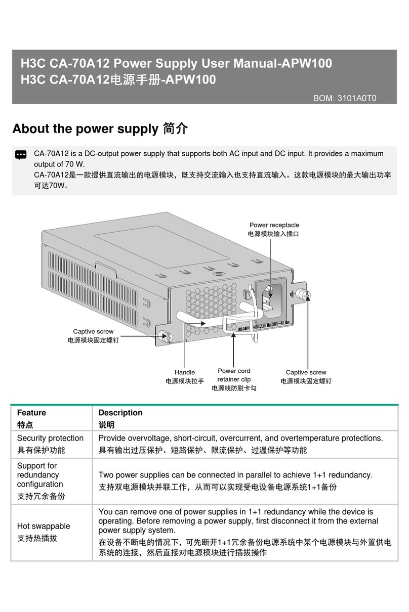
H3C DP52-52 User manual

H3C DP52-52 Power Adapter
User Guide
New H3C Technologies Co., Ltd.
http://www.h3c.com
Document version: 5W100-20200903

Copyright © 2020, New H3C Technologies Co., Ltd. and its licensors
All rights reserved
No part of this manual may be reproduced or transmitted in any form or by any means without prior written
consent of New H3C Technologies Co., Ltd.
Trademarks
Except for the trademarks of New H3C Technologies Co., Ltd., any trademarks that may be mentioned in this
document are the property of their respective owners.
Notice
The information in this document is subject to change without notice. All contents in this document, including
statements, information, and recommendations, are believed to be accurate, but they are presented without
warranty of any kind, express or implied. H3C shall not be liable for technical or editorial errors or omissions
contained herein.
Environmental protection
This product has been designed to comply with the environmental protection requirements. The storage, use,
and disposal of this product must meet the applicable national laws and regulations.

Preface
This document provides a user guide for installing the DP52-52 Power Adapter. It also covers the
power supply views, technical specifications, and installation environment and guidelines.
This preface includes the following topics about the documentation:
•
Audience.
•
Conventions.
•
Documentation feedback.
Audience
This documentation is intended for:
•
Network planners.
•
Field technical support and servicing engineers.
•
Network administrators working with the H3C DG-240-55 industrial power supply.
Conventions
The following information describes the conventions used in the documentation.
Command conventions
Convention
Description
Boldface Bold text represents commands and keywords that you enter literally as shown.
Italic Italic text represents arguments that you replace with actual values.
[ ] Square brackets enclose syntax choices (keywords or arguments) that are optional.
{ x | y | ... }
Braces enclose a set of required syntax choices separated by vertical bars, from which
you select one.
[ x | y | ... ]
Square brackets enclose a set of optional syntax choices separated by vertical bars,
from which you select one or none.
{ x | y | ... } *
Asterisk marked braces enclose a set of required syntax choices separated by vertical
bars, from which you select a minimum of one.
[ x | y | ... ] *
Asterisk marked square brackets enclose optional syntaxchoices separated by vertical
bars, from which you select one choice, multiple choices, or none.
&<1-n> The argument or keyword and argument combination before the ampersand (&) sign
can be entered 1 to n times.
# A line that starts with a pound (#) sign is comments.
GUI conventions
Convention
Description
Boldface Window names, button names, field names, and menu items are in Boldface. For
example, the New User window opens; click OK.
> Multi-level menus are separated by angle brackets. For example, File > Create >
Folder.

Symbols
Convention
Description
WARNING!
An alert that calls attention to important information that if not understood or followed
can result in personal injury.
CAUTION:
An alert that calls attention to important information that if not understood or followed
can result in data loss, data corruption, or damage to hardware or software.
IMPORTANT:
An alert that calls attention to essential information.
NOTE:
An alert that contains additional or supplementary information.
TIP:
An alert that provides helpful information.
Network topology icons
Convention
Description
Represents a generic network device, such as a router, switch, or firewall.
Represents a routing-capable device, such as a router or Layer 3 switch.
Represents a generic switch, such as a Layer 2 or Layer 3 switch, or a router that
supports Layer 2 forwarding and other Layer 2 features.
Represents an access controller, a unified wired-WLAN module, or the access
controller engine on a unified wired-WLAN switch.
Represents an access point.
Represents a wireless terminator unit.
Represents a wireless terminator.
Represents a mesh access point.
Represents omnidirectional signals.
Represents directional signals.
Represents a security product, such as a firewall, UTM, multiservice security
gateway, or load balancing device.
Represents a security module, such as a firewall, load balancing, NetStream, SSL
VPN, IPS, or ACG module.
Examples provided in this document
Examples in this document might use devices that differ from your device in hardware model,
configuration, or software version. It is normal that the port numbers, sample output, screenshots,
and other information in the examples differ from what you have on your device.

T
T
T
T

Documentation feedback
You can e-mail your comments about product documentation to info@h3c.com.
We appreciate your comments.

i
Contents
1 About the H3C DP52-52 power adapter······················································1
Device view························································································································································1
Technical specifications·····································································································································1
2 Safety guidelines and warnings ··································································3
Safety guidelines················································································································································3
Safety warnings··················································································································································3
3 Installing the power adapter········································································4
Examining the installation environment ·············································································································4
Installing the power adapter·······························································································································4
4 Connecting the power wires········································································5

1
1 About the H3C DP52-52 power adapter
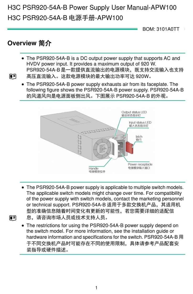
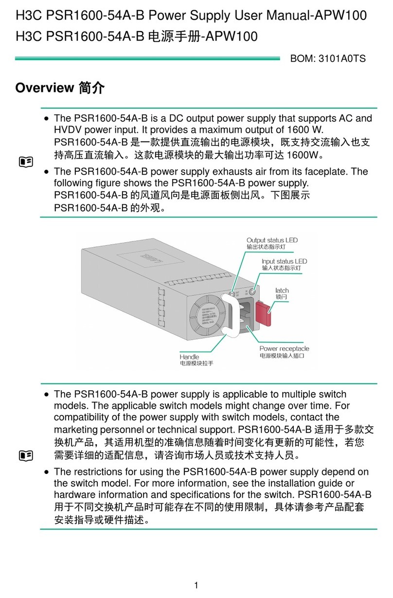
The H3C DP52-52 power adapter is a 12V-input and 52V-output non-isolated regulated DC power
supply. It provides protections against overcurrent output, undervoltage input, and overtemperature
conditions. It is suitable for supplying power to industrial switches for being waterproof, dustproof,
anti-shock, small in size, easy to install, and stable in performance.
Device view
Figure1-1 View
(1) Screw hole
(2) Positive DC input wire
(3) Negative DC input wire
(4) Negative DC output wire
(5) Positive DC output wire
Technical specifications
Table1-1 Technical specifications
Item
Specifications
Dimensions (H × W × D) 57 × 64 × 22 mm (2.24 × 2.52 × 0.87 in)
Net weight 300 g (10.58 oz)
Input voltage range 11 VDC to 15 VDC
Rated input voltage 12 VDC
Rated output voltage 52 VDC
Output voltage range 50.44 VDC to 53.56 VDC
Rated output current 1.0 A
Rated output power 52 W

2
Protection rating IP68

3
2 Safety guidelines and warnings
To avoid possible device damage or bodily injury, read the following safety guidelines and warnings
carefully before using the power adapter.
Safety guidelines
•
Keep good ventilation and heat dissipation during the operating process of the power adapter
to ensure long-term reliability.
•
Use the power adapter in an environment that meets the specified requirements in Table3-1.
•
The potentiometer in the power adapter can be adjusted only by qualified personnel as
required and they must be aware of the impact of the adjustment.
•
Do not operate the power adapter in an environment with volatile gases or flammable
materials.
•
Do not remove the cover from the power adapter. Do not touch, repair, or replace the
components inside the power adapter.
•
Cut off power immediately if smoke or unpleasant smell is emitted during the startup or
operating process of the power adapter.
Safety warnings
•
Once the power adapter enters the protection mode, stop the power adapter immediately and
handle the power adapter according to the relevant maintenance guidelines.
•
Only qualified personnel can connect the power adapter to a power source equipment.
•
Power might be still present on the adapter after it is just shut down. Shut down the adapter
and wait for five minutes before working on the power adapter.
•
Pay attention to the safety signs. To avoid electric shocks and burns, do not touch the location
with your hands directly where there are safety warning signs and high-voltage signs.

4
3 Installing the power adapter
Examining the installation environment
Table3-1 Requirements for the installation environment
Item
Specifications
Operating temperature –30°C to +60°C (–22°F to +140°F)
Storage temperature –40°C to +85°C (–40°F to +185°F)
Relative humidity (noncondensing) 5% to 95%
Altitude
≤5000 m (16404.20 ft)
The operating temperature decreases by 1°C (33.8°F) for every
increase of 200 m (656.17 ft) above 3000 m (9842.52 ft) in altitude.
Cooling method Natural cooling
Installing the power adapter
The following installs the power adapter on a DIN rail:
1. Wear an ESD wrist strap and make sure the wrist strap has good skin contact and is reliably
grounded.
2. Determine the power adapter installation position on the DIN rail according to the location of
power source equipment and the input and output cable lengths of the power adapter.
3. Thread two cable ties through the power adapter screw holes and through the DIN rail
installation holes, and fasten the cable tie to secure the power adapter to the DIN rail.

5
4 Connecting the power wires
CAUT
ION:
•
To protect the power adapter from damages caused by incorrect power cord connections,
identify the input, output, positive (+), and negative (-) marks on the power adapter before
connecting the power wires.
•
Before connecting the power wires, turn off the circuit breaker at the power input end. You can
use a 10 Acircuit breaker.
The DC power source equipment in Figure4-2 is for illustration only. Prepare a DC power source
equipment that meets the voltage requirements yourself.
To connect the power wires:
1. Wear an ESD wrist strap and make sure the wrist strap has good skin contact and is reliably
grounded.
2. Connect the positive (yellow) and negative (black) DC output wires of the adapter to the
positive and negative input terminals of the device to which the adapter will supply power,
respectively. Then fasten the wires.
3. Connect the positive (red) and negative (black) DC input wires of the adapter to the positive
and negative poles of the power source equipment, respectively. Then fasten the wires.
4. Verify that the power wires are connected correctly and then turn on the circuit breaker at the
power input end.
Figure4-2 Connecting the power wires
Table of contents
Other H3C Power Supply manuals

H3C
H3C XE 200/2000 IP User manual

H3C
H3C PSR920-54A-B User manual

H3C
H3C DPS-800W-12A-48V User manual

H3C
H3C PSR2400-D User manual

H3C
H3C CA-70A12 User manual

H3C
H3C DG-240-55 Operating and maintenance manual

H3C
H3C PSR1200B-12A User manual

H3C
H3C PS-2551-9L3 User manual

H3C
H3C External PoE Power System PSE2500-A3 User manual

H3C
H3C PS-2202-11L User manual