ABB Infinity B G240 System -48V User manual

Page 1
© 2021 ABB. All rights reserved.
QUICK START GUIDE
Infinity B (NE-B) G240 System -48V, +24V,
+24V/-48V or –48V/+24V
•
Use a #10 or 1/4” diameter double-hole lug on 5/8”
center (Not provided) to ground the chassis; Torque
connections to 35 in- lbs using 5/16” nut driver
Shelf Chassis
Ground Options
The ac input panel is directly above the top row of
power modules. 1” and 1-1/2” conduit knockouts are
located on the left and right ends of the ac panel.
Each rectifier position is factory configured for
individual 208/220VAC inputs. Individual inputs
require 20A protectors and 10 AWG wires. Two
rectifier positions can be fed from one ac source by
installing the provided jumpers. When using one
input for two rectifiers a 40A protector and 8 AWG
wire is required. Recommend two 1-1/2” conduits
feeding up to 8 rectifiers per conduit; (16) 10 AWG
Rectifiers Rectifiers Rectifiers Rectifiers
41 42 31 32 21 22 11 12 13 14 23 24 33 34 43 44
L1 L1 L1 L1 L1 L1 L1 L1 L1 L1 L1 L1 L1 L1 L1 L1
L2 L2 L2 L2 L2 L2 L2 L2 L2 L2 L2 L2 L2 L2 L2 L2
0
JJll
111111111111111
a
ii11111m1111i1i
.tllllllllllllllllll
•
n1111m1111if11
'.!
•lllllllllllllllllb
-•=-
of-•
11:1
II
III
IIIIII
III
UU
'
J.
.IIIIIIIIIIIIIIIUlb
:
u11111m111iii
w
.!
1
1111111111111111111
n
fif1
1
um11111111
•
.!
1
ll111111lllllllllb
·m11111m111mr
,
:i
:iHHlllllll
llllllb
• i
iii111111111111
W
11
1111111111111111111
•
HI
111111
111
111111
'
Jl
1111
11111,1,
Install
the
shelf
with
a
minimum
gap
of
3 inches
behind
the
system
to
allow
proper
airflow.
Attach
the
shelf
to
the
frame
using
a
minimum
of
twelve
(Six
on
each
side)
12-24screws.
Warning: The
equipment
and
subassembly
ports
can
only
be
connected
to
shielded
intra-building
cabling
grounded
at
both
ends. The
ports
are
suitable
for
connection
to
intrabuilding
or
unexposed
wiring
or
cabling.
Tools required:
• Torquewrench
(0-240
in-lb/
28
Nm)
5/16,"7
/16"
and
1/2"
nut
drivers
•
Screw
Drivers -
Flat
&2 Phillips • Wire cuttersandstrippers
• Cable
crimpers
Step
1 -ConnectShelfGround
Step
2 - ConnectAC
Inputs

Page 2
© 2021 ABB. All rights reserved.
QUICK START GUIDE
wires plus ground or (8) 8 AWG wires plus ground per conduit.
Rectifiers are identified by their position in the shelves. See diagram.
Danger: Disconnect all ac branch circuits prior to making ac con- nections to the system. When connecting to utility
source, ensure compliance to all local and national wiring rules.
Caution: When routing AC ensure cables do not come in contact with sharp or rough surfaces that may damage
insulation and cause a short circuit.
Rectifier shelf position and I
Step Action
1
For applications using one ac feed per rectifi- er: Attach the
individual 10 AWG AC input wires for each position and torque
the wire clamps to 10 inch-lbs.
2
For applications using one ac feed for every two rectifiers; Use
a pair of needle nose pliers to remove the divider between the
individual rectifier wire clamps that will share the ac input.
3
Install a strap between the two terminal blocks. Secure the
strap in posi- tion with two screws and torque to 10 inch lbs.
Straps and screws are provided.
4Attach the 8 AWG AC input wires to the terminal blocks and
torque the wire clamps to 10 inch-lbs.
Rectifier 11 Rectifier 12 Rectifier 13 Rectifier 14
Rectifier 21 Rectifier 22 Rectifier 23 Rectifier 24
Rectifier 31 Rectifier 32 Rectifier 33 Rectifier 34
Rectifier 41 Rectifier 42 Rectifier 43 Rectifier 44
Step
3 -
Connect
AC
Inputs
(Continued)
--
--
--
Jl
1111
11111,1,

Page 3
© 2021 ABB. All rights reserved.
QUICK START GUIDE
Two controller options are available; CC109128402 NE843A Pulsar slot controller or CC109132024 Millennium II Rack
mounted controller. Controller product manuals are available at abbpowerconversion.com
The Pulsar slot controller mounts in the left most position of the top shelf (as shown in the diagram on page 1). All
controller connections are accessible with the controller installed. Refer to the table below for detailed alarm
connection information. Before in- stalling the controller configure the bus reference voltage and alarm output
jumpers;
1. Set Jumper 11 to (+) for +24Vdc systems or (-) for -48V/-24V (Factory Default) systems.
2. Set jumpers 1 thru 10 for the ten alarm relays as “Close” or “Open” on alarm; Factory default setting is “Close” on alarm. The
Alarm relay jumpers are located under the sliding cover on top of the controller, see figure below.
Note: The optional Millennium II rack mount controller can be used instead of the Pulsar when additional controller
features are required. See the Millennium II Product Manual at abbpowerconversion.com for more information.
System reference voltage and alarm output jumpers.
J1 Optional system
Interface. See table
below.
J2 Thermal probes. See
back page.
J3 Auxiliary Inputs
J5 LAN
Bus reference V and
Alarm Relay Jumpers
under cover
J4 Alarm Outputs
Close on Alarm
Open on Alarm
10 987654321
11
+24
-48V /+24 V

Page 4
© 2021 ABB. All rights reserved.
QUICK START GUIDE
J1 provides access to inputs required for basic system information, such as; load current, Major fuse alarm and open
battery string.
J1 Cable (included); CC848914176 is a 1’ cable with end-to-end connectors to connect the inputs described in the
table below.
J4 (20 pin connector) provides access to customer alarm outputs. Alarm outputs are shown below.
Available alarm cables;
CC848890137 5’
CC109157442 15’
CC848817635 50’
CC848817643 150’
J1 System Interface connections Color
Shunt + W/BK
Shunt - O-BK
Fuse Alarm Major 24V
Open Battery String
Fuse Alarm Major 48V
Standard Controller Alarm Output Defaults Pin Color Option 1 Color Option 2
PCR Power Critical BL BL
PCR_C Power Critical_C 11 BL/BK
PMJ Power Major
PMJ_C Power Major_C 12 O/BK
PMN Power Minor
PMN_C Power Minor_C 13 G/BK
R1 Battery On Discharge BR
R1_C Battery On Discharge_C
(BD_C) 14 W/BK
R2 Very Low Voltage (VLV) BK
R2_C Very Low Voltage_C (VLV_C) 15 BK/W
R3 Fuse Alarm Major (FAJ) BL BL/W
R3_C Fuse Alarm Major_C (FAJ_C) 16 BL/R
R4 AC Fail (ACF) O/R
R4_C AC Fail_C (ACF_C) 17
R5 Rectifier Fail (RFA) G/W
R5_C Rectifier Fail_C (RFA_C) 18 R/G
R6 Mult. Rectifier Fail (MRFA) BR W/R
R6_C Mult. Rectifier Fail_C
(MRFA_C) 19 R/W
R7 High Voltage (HV) 10 BK/R
R7_C High Voltage_C (HV_C) 20 R/BK

Page 5
© 2021 ABB. All rights reserved.
QUICK START GUIDE
J3 (10 pin connector) provides access to the auxiliary inputs. Default alarm descriptions are shown in the table below
and may be changed as needed using web pages or Easyview2.
Available input cables;
CC848890153 5’
CC848865980 15’
CC848817651 50’
CC848817668 150’
The DC can be configured for -48V, +24V, -48V/+24V or +24V/-48V depending on the power modules; -48V rectifiers,
+24V Rectifiers or combination of rectifiers and converters. The outputs are located on the rear of the shelf. The
shelf is designed to distribute bulk power only; there are no DC output protectors in the shelf. Lug landings
accommodate 3/8” di- ameter lugs on 1” centers spaced 1.75“ apart. Three 750 MCM Flex lugs can be connected per
bus. Bus extensions are provided to land four additional cables back to back.
Standard Controller Alarm Pin Color Standard Controller Alarm Pin Color
Air Con Fail BK EPO
Air Con Fail_Return EPO_Return 10
Door Open BR Hi ext. Temp.
Door Open_Return Hi ext. Temp._Return
Battery Test/GSTR Low ext. Temp. BL
Battery Test_Return Low ext. Temp._Return
Aux PMJ Input

Page 6
© 2021 ABB. All rights reserved.
QUICK START GUIDE
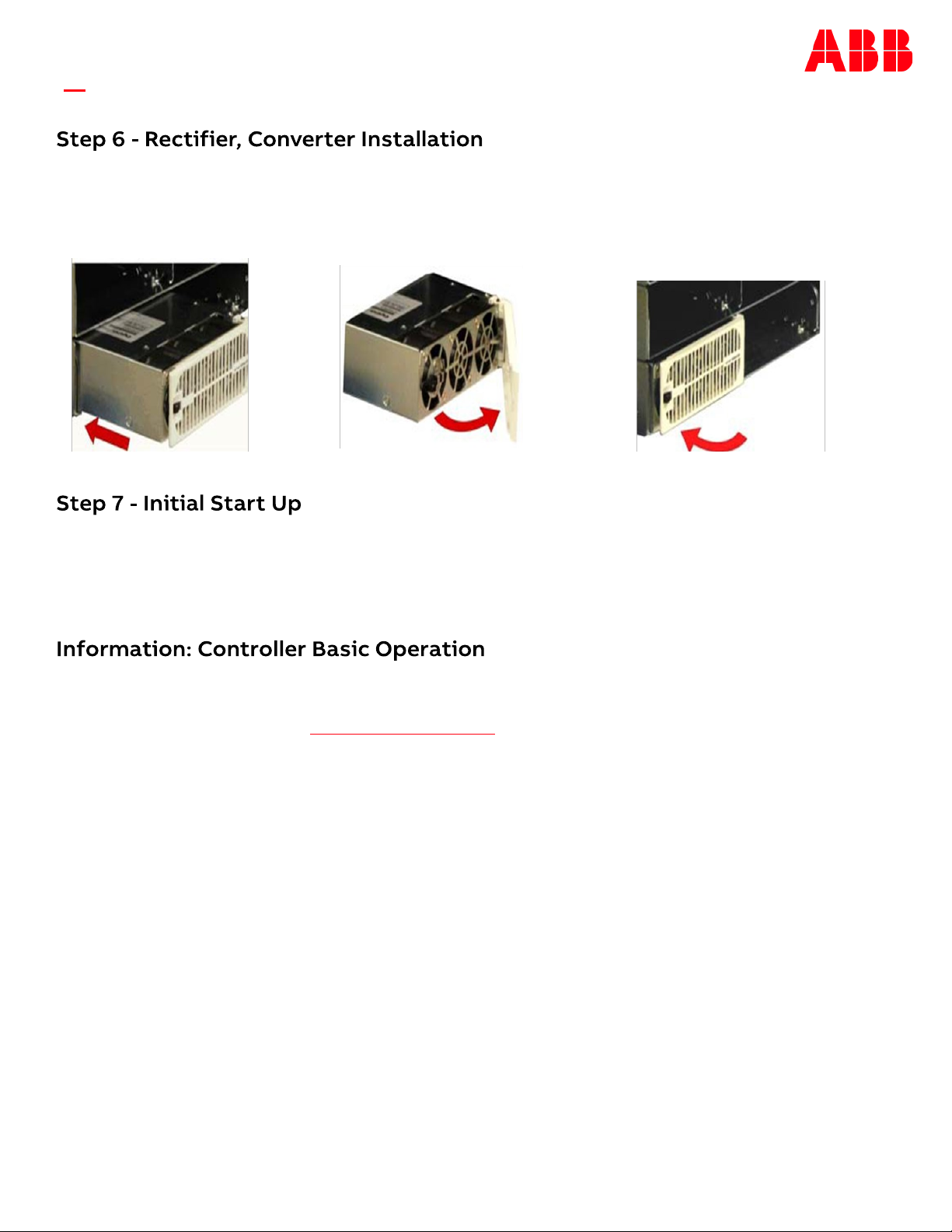
Slide the rectifier/converter
into the slot approximately
3/4 of the way.
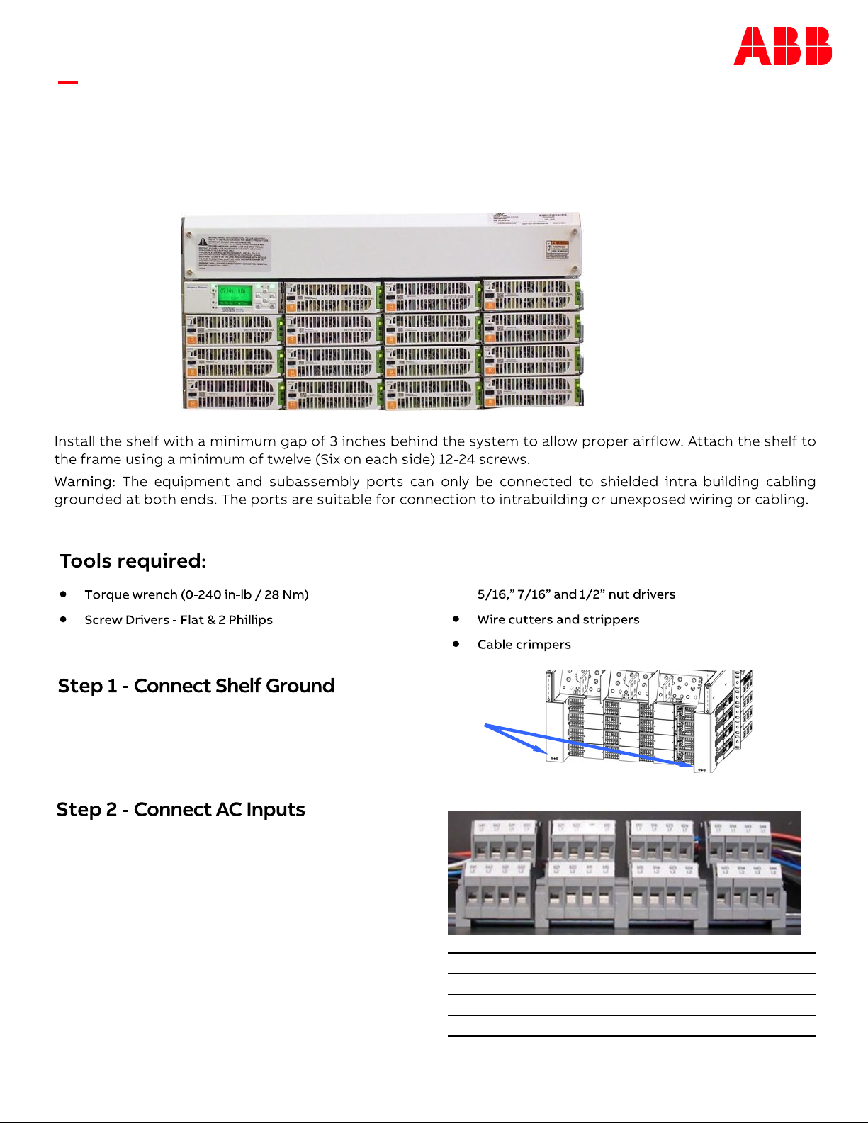
Verify all AC, DC, Alarm and system interface connections are complete and secure. If rectifiers have not yet been
installed, install rectifiers now as described previously. Once this is complete turn on the AC input breakers. As each
rectifier is installed, the controller automatically identifies the new rectifier and begins communication. If there are
no alarms, make adjustments to the default settings on the controller as required for this installation. Using the
front panel menu to configure settings and functions is intuitive. Refer to the menu map on the next page.
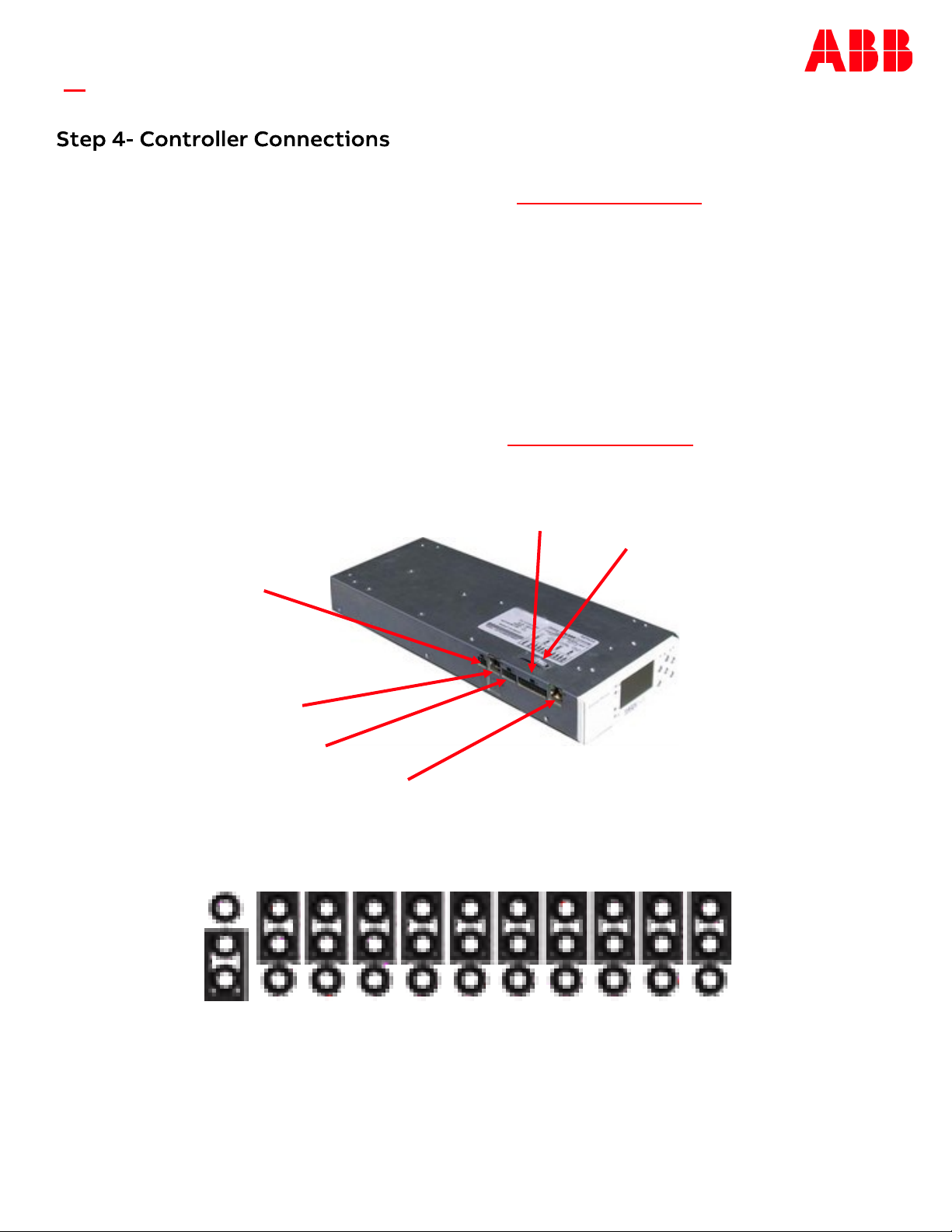
Viewing and changing system parameters from the factory defaults can be accomplished in several ways; A) front
display, B) Craft Port on front of controller using a laptop with EasyView2 or HyperTerminal. EasyView2 (GUI)
software can be downloaded from abbpowerconversion.com , C) J5 LAN port in Static, Client, or Server mode. Static
and Client modes are for accessing web pages through a network. Server mode allows local access to the controller
web pages directly from a laptop connected to J5 LAN port; Menu>Configure>Communication Ports>Network
Settings>DHCP (Server). Server mode default IP address is 192.168.2.1. With the controller set to Server type the
default IP address in the web browser address field. Server mode is a temporary setting, once configuration is
complete reset the controller to Client or Static before connecting to the network. Static is the factory default
setting and the typical setting for most networks. Warning: Do not connect J5 LAN port to a network when set to
Server.
Controller Alarm Status: The display changes colors; Green = Normal, Amber = Minor Alarm, Red = Critical/Major
Alarm
Some alarms may occur during initial installation; example: thermal probe fail or Major/Minor communication fail .
To clear these alarms from the Controller Display: follow the menu path; Menu > Control/Operation > Clear Events or
Uninstall Equipment.
Using web pages or EasyView2; Select the Maintenance tab > clear latched events and clear missing devices.
Verify Basic Installation Settings: To verify Date, Time, Battery Type, number of strings and float voltage for this
application using the Controller Display: follow the menu path; Menu > Configuration > System Settings and Menu >
Configuration > Batteries. Using web pages or EasyView2; Select the Installation Tab to set the Date, Time. Site ID
and Site Description. Select the Settings Tab > Battery Management to verify Battery Type and set number of
battery strings installed.
Open the faceplate by sliding the
face- plate latch to the left until the
faceplate releases and swings outward.
Slide the unit into the slot until it engages
with the back of the shelf. Swing the
faceplate closed to seat the rectifier/
converter. Verify the faceplate is latched.

Page 7
© 2021 ABB. All rights reserved.
QUICK START GUIDE
Default Voltage Settings and Ranges Range Valve-Reg Flooded NiCd
Rectifier Float Selective High Voltage Shutdown -50 to -60V 58.50 58.50 58.50
High Float Voltage Major Alarm -50 to -60V 57.00 57.00 57.00
High Float Voltage Minor Alarm -50 to -60V 56.00 56.00 56.00
Rectifier/System Float Voltage -42 to -56.5V 54.48 52.08 54.40
Battery on Discharge Float Alarm -46 to -55V 51.00 50.00 51.00
Very Low Float Voltage Alarm -40 to -51V 46.00 46.00 46.00
Rectifier On Threshold -40 to -51V 44.00 44.00 44.00
Front
Display
Menu
Map

Page 8
© 2021 ABB. All rights reserved.
QUICK START GUIDE
Information: Battery Monitoring (Optional)
Battery Monitoring is accomplished with a “Daisy Chained” series of QS873 probes connected to J2. The
Probes are used to monitor battery temperature and mid-string voltage (ES771 required to monitor
voltage). Bolt the Probe under the “–“ terminal connector hardware; NOT under the connecting lug.
Temperature monitoring
Temperature and voltage monitoring

Page 9
© 2021 ABB. All rights reserved.
ABB
601 Shiloh Rd.
Plano, TX USA
abbpowerconversion.com
We reserve the right to make technical changes or modify the
contents of this document without prior notice. With regard to
purchase orders, the agreed particulars shall prevail. ABB AG does
not accept any responsibility whatsoever for potential errors or
possible lack of information in this document.
We reserve all rights in this document and in the subject matter
and illustrations contained therein. Any reproduction, disclosure
to third parties or utilization of its contents–in whole or in
parts – is forbidden without prior written consent of ABB.
Copyright© 2021ABB
All rights reserved
This manual suits for next models
7
Other ABB Power Supply manuals

ABB
ABB ODPSE230C User manual

ABB
ABB 4234 600 User manual

ABB
ABB CP-T 24/20.0 User manual

ABB
ABB 83310-500 User manual

ABB
ABB CP-ASI/2.8 User manual

ABB
ABB CP-E Series User manual

ABB
ABB Infinity S J5964803 L209 User manual

ABB
ABB Symphony Harmony Series User manual

ABB
ABB NES48-23-AC1-PS4-DC1E-LVBD User manual

ABB
ABB CPS3200U User manual

ABB
ABB CPS2400U User manual

ABB
ABB ACS550-01 User manual

ABB
ABB CPS6000 User manual

ABB
ABB CP-E 5/3.0 User manual

ABB
ABB ProcessMaster 500 User manual

ABB
ABB NES4812-23-AC1-PS4-DC1E-LVBD User manual

ABB
ABB NES48-19-4U-AC7-PS3-DIN15B250P-LVBD-ACSPD User manual

ABB
ABB RPB 520 User manual

ABB
ABB 4234 600 User manual

ABB
ABB CPS6000 User manual