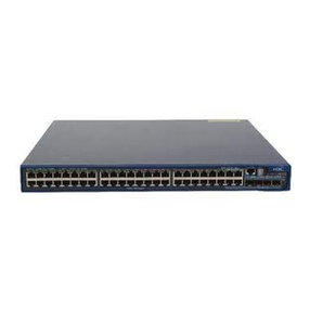
H3C S9500 Series Installation instructions

Command Manual – Clock Monitoring
H3C S9500 Series Routing Switches Table of Contents
i
Table of Contents
Chapter 1 Clock Monitoring Configuration Commands............................................................1-1
1.1 Clock Monitoring Configuration Commands......................................................................1-1
1.1.1 clock........................................................................................................................1-1
1.1.2 clock forcessm.........................................................................................................1-2
1.1.3 clock lpuport............................................................................................................1-3
1.1.4 clock priority ............................................................................................................1-4
1.1.5 clock sa-bit ..............................................................................................................1-4
1.1.6 clock ssm.................................................................................................................1-5
1.1.7 clock ssmcontrol......................................................................................................1-6
1.1.8 clock stop warm-up .................................................................................................1-7
1.1.9 display clock basephase.........................................................................................1-8
1.1.10 display clock config ...............................................................................................1-8
1.1.11 display clock d/a..................................................................................................1-10
1.1.12 display clock device ............................................................................................1-10
1.1.13 display clock lpuport............................................................................................1-13
1.1.14 display clock phase-lock-state ............................................................................ 1-14
1.1.15 display clock priority............................................................................................1-15
1.1.16 display clock self-test-result................................................................................1-16
1.1.17 display clock source............................................................................................1-17
1.1.18 display clock ssm-level........................................................................................1-18
1.1.19 display clock ssm-output.....................................................................................1-19
1.1.20 display clock version ...........................................................................................1-20
1.1.21 display clock work-mode.....................................................................................1-21
Command Manual – Clock Monitoring
H3C S9500 Series Routing Switches Chapter 1 Clock Monitoring Configuration
Commands
1-1
Chapter 1 Clock Monitoring Configuration
Commands
Note:
The clock monitoring configuration commands are available when the SRPUs are
installed with a clock module. If the SRPUs are not installed with a clock module, all
these commands are invisible. For information about SRPUs installed with a clock
module, refer to the S9500 Series Routing Switches Installation Manual.
1.1 Clock Monitoring Configuration Commands
1.1.1 clock
Syntax
clock { auto | manual source source-number }
undo clock work-mode
View
System view
Default Level
2: System level
Parameters
auto: Sets the clock monitoring module to work in auto mode.
manual source source-number: Sets the clock monitoring module to work in manual
mode. source-number indicates the primary clock source number in manual mode.
Description
Use the clock command to set the work mode of the SRPU clock monitoring module,
that is, the mode the clock monitoring module uses to choose clock source, either auto
mode or manual mode.
Use the undo clock work-mode command to restore the default.
By default, the work mode is auto.

Command Manual – Clock Monitoring
H3C S9500 Series Routing Switches Chapter 1 Clock Monitoring Configuration
Commands
1-2
Note that:
zBefore configuring the work mode as manual, you should use the display clock
source command to view the clock source state. Only clock sources working
normally can be successfully configured as the primary clock source.
zAfter you set the work mode of the clock monitoring module, it takes a period of
time for device response. In this case, you can check whether your configuration
takes effect through the display clock device command and the logging
information.
Examples
# Set the working mode of the SRPU clock monitoring module to manual, and the
primary clock source to 1.
<Sysname> system-view
[Sysname] clock manual source 1
1.1.2 clock forcessm
Syntax
clock forcessm { on | off } source source-number
View
System view
Default Level
2: System level
Parameters
on: Specifiesnot to derive the SSM levels from the clock source, namely, uses the SSM
levels manually configured by users.
off: Derives the SSM levels from the clock source. The user-configured SSM levels are
not effective.
source-number: Number of clock source.
Description
Use the clock forcessm command to set whether to derive the SSM levels from clock
source or to configure the SSM levels manually by users.
By default, the SSM levels are manually configured.
Related commands: clock ssm.
Examples
# Derive SSM level from the clock source 1.

Command Manual – Clock Monitoring
H3C S9500 Series Routing Switches Chapter 1 Clock Monitoring Configuration
Commands
1-3
<Sysname> system-view
[Sysname] clock forcessm off source 1
1.1.3 clock lpuport
Syntax
clock lpuport interface-type interface-number
undo clock lpuport interface-type interface-number
View
System view
Default Level
2: System level
Parameters
interface-type interface-number: Specifies a port by its type and number.
Description
Use the clock lpuport command to specify the input port of the line clock source (LPU
port).
Use the undo clock lpuport command to restore the default.
By default, the LPU port is the first configurable port by port name in lexical order of the
ports on the interface card.
Note:
zFor a WAN interface card, if you set the port clock to work in slave mode, you must
use this command to select the LPU port of the clock source of the interface card.
zThe clock mode of the LPU port of the line clock source must be slave.
Examples
# Set the LPU port of the line clock source as interface POS 3/1/1.
<Sysname> system-view
[Sysname] clock lpuport pos 3/1/1

Command Manual – Clock Monitoring
H3C S9500 Series Routing Switches Chapter 1 Clock Monitoring Configuration
Commands
1-4
1.1.4 clock priority
Syntax
clock priority value source source-number
undo clock priority source source-number
View
System view
Default Level
2: System level
Parameters
value: Priority value.
source-number: Number of clock source.
Description
Use the clock priority command to the reference source priority.
Use the undo clock priority command to the restore the default.
By default, the priority of all reference sources is 255.
Examples
# Set the priority of reference source 2 to 3.
<Sysname> system-view
[Sysname] clock priority 3 source 2
1.1.5 clock sa-bit
Syntax
clock sa-bit { sa4 | sa5 | sa6 | sa7 | sa8 } source source-number
undo clock sa-bit source source-number
View
System view
Default Level
2: System level
Parameters
sa4: Indicates that the bit position is sa4.

Command Manual – Clock Monitoring
H3C S9500 Series Routing Switches Chapter 1 Clock Monitoring Configuration
Commands
1-5
sa5: Indicates that the bit position is sa5.
sa6: Indicates that the bit position is sa6.
sa7: Indicates that the bit position is sa7.
sa8: Indicates that the bit position is sa8.
source-number: Number of Bits clock source.
Description
Use the clock sa-bit command to set the bit position used to transmit Bits clock source
information.
Use the undo clock sa-bit command to restore the default.
By default, sa4 is used to carry the SSM information.
Examples
# Set the bit position used to transmit theSSM information of Bits clock source 1 to sa5.
<Sysname> system-view
[Sysname] clock sa-bit sa5 source 1
1.1.6 clock ssm
Syntax
clock ssm { dnu | lnc | prc | sets | tnc | unknown } source source-number
undo clock ssm source source-number
View
System view
Default Level
2: System level
Parameters
dnu: Specifies the SSM level to DNU. (DoNotUse).
lnc: Specifies the SSM level to LNC (G.812 local node clock signal).
prc: Specifies the SSM level to PRC (G.811 clock signal).
sets: Specifies the SSM level to SETS (SDH device clock source signal).
tnc: Specifies the SSM level to TNC (G.812 transit node clock signal).
unknown: Specifies the SSM level to unknown (Unknown synchronization quality).
source-number: Number of reference source.

Command Manual – Clock Monitoring
H3C S9500 Series Routing Switches Chapter 1 Clock Monitoring Configuration
Commands
1-6
Description
Use the clock ssm command to set the SSM levels of the reference sources.
Use the undo clock ssm command to restore the default.
By default, the SSM level of all reference sources is unknown.
Note that:
zFor the line clock source, the SSM level configured is that of the clock source.
zFor Bits clock source, if the input signal is a 2048 kbps (E1) signal and the clock
forcessm off source is executed, the clock source adopts the SSM level derived
from the input signals and the SSM configured is omitted.
zFor Bits clock source, if the input signal is a 2048 kHz signal or a 2048 kbps signal
and the clock forcesssm on source command is executed, the clock source
adopts the SSM level configured.
zAfter you set the SSM levels of the reference sources, it takes a period of time for
device response. In this case, you can check whether your configuration takes
effect through the display clock ssm-level command and the logging
information.
Examples
# Set the SSM level of clock source 1 to DNU.
<Sysname> system-view
[Sysname] clock ssm dnu source 1
1.1.7 clock ssmcontrol
Syntax
clock ssmcontrol { on | off }
undo clock ssmcontrol
View
System view
Default Level
2: System level
Parameters
on: Activates SSM level.
off: Deactivates SSM level.
Description
Use the clock ssmcontrol command to activate or deactivate SSM level.

Command Manual – Clock Monitoring
H3C S9500 Series Routing Switches Chapter 1 Clock Monitoring Configuration
Commands
1-7
Use the undo clock ssmcontrol command to restore the default.
By default, SSM level is deactivated.
Note that:
zWhen SSM level is activated, the SSM level becomes the decisive factor in
reference source automatic selection.
zWhen SSM level is not activated, you can still set and view the SSM levels, but
they are ignored in reference source automatic selection are decided by reference
source priority.
Examples
# Activate SSM of clock monitoring module.
<Sysname> system-view
[Sysname] clock ssmcontrol on
1.1.8 clock stop warm-up
Syntax
clock stop warm-up
View
System view
Default Level
2: System level
Parameters
None
Description
Use the clock stop warm-up command to manually stop the clock monitoring module
from warming up and enable it to work normally.
Examples
# Manually stop the clock monitoring module from warming up and enable it to work
normally.
<Sysname> system-view
[Sysname] clock stop warm-up

Command Manual – Clock Monitoring
H3C S9500 Series Routing Switches Chapter 1 Clock Monitoring Configuration
Commands
1-8
1.1.9 display clock basephase
Syntax
display clock basephase
View
Any view
Default Level
1: Monitor level
Parameters
None
Description
Use the display clock basephase command to view the synchronized clock base
phase.
Examples
# View the synchronized clock base phase
<Sysname> display clock basephase
clock base phase : 0x0
The above prompt information indicates that the synchronized clock base phase is 0.
1.1.10 display clock config
Syntax
display clock config
View
Any view
Default Level
1: Monitor level
Parameters
None
Description
Use the display clock config command to display the current configurations of the
clock monitoring module.

Command Manual – Clock Monitoring
H3C S9500 Series Routing Switches Chapter 1 Clock Monitoring Configuration
Commands
1-9
Examples
# View the current configurations of the clock monitoring module.
<Sysname> display clock config
Clock module current configuration:
Work mode : auto
SSM participate in control : no
Reference Priority SSM level Forcessm Sa-bit Lpu port
1 255 UNKNOWN yes 4 N/A
2 255 UNKNOWN yes 4 N/A
3 255 UNKNOWN N/A N/A -
4 255 UNKNOWN N/A N/A -
5 255 UNKNOWN N/A N/A -
6 255 UNKNOWN N/A N/A -
7 255 UNKNOWN N/A N/A -
8 255 UNKNOWN N/A N/A -
9 255 UNKNOWN N/A N/A -
10 255 UNKNOWN N/A N/A -
11 255 UNKNOWN N/A N/A -
12 255 UNKNOWN N/A N/A -
13 255 UNKNOWN N/A N/A -
14 255 UNKNOWN N/A N/A -
15 255 UNKNOWN N/A N/A -
16 255 UNKNOWN N/A N/A -
17 255 UNKNOWN N/A N/A -
18 255 UNKNOWN N/A N/A -
Table 1-1 display clock config command output description
Field Description
Clock module current configuration: Current configuration of the clock monitoring
module
Work mode Work mode of the clock monitoring module,
with auto indicating the auto mode and
manual indicating the manual mode.)
SSM participate in control Whether SSM is activated
Reference Serial number of the reference source
Priority Priority of the reference source
SSM level SSM level of the reference source
Forcessm Derive mode of the SSM level, with yes
meaning derived from Bits clock source and
N/A meaning this function is not supported.

Command Manual – Clock Monitoring
H3C S9500 Series Routing Switches Chapter 1 Clock Monitoring Configuration
Commands
1-10
Field Description
Sa-bit Bits used to transmit SSM level information
of the Bits clock source
Lpu port Input port of the line clock source (N/A
indicates this function is not supported and
(;) indicates this port is not configured)
1.1.11 display clock d/a
Syntax
display clock d/a
View
Any view
Default Level
1: Monitor level
Parameters
None
Description
Use the display clock d/a command to view the D/A value of the Digital to Analog
Converter (DAC) in the clock monitoring module.
Examples
# View the D/A value of the DAC in the clock monitoring converter.
<Sysname> display clock d/a
DAC Voltage : 2048
The above prompt information indicates that the D/A value of the DAC in the clock
monitoring converter is 2048 V.
1.1.12 display clock device
Syntax
display clock device
View
Any view

Command Manual – Clock Monitoring
H3C S9500 Series Routing Switches Chapter 1 Clock Monitoring Configuration
Commands
1-11
Default Level
1: Monitor level
Parameters
None
Description
Use the display clock device command to view detailed information of the clock
monitoring module.
Examples
# View detailed information of the clock monitoring module.
<Sysname> display clock device
Clock module detail information:
Clock module state is OK
SRAM state: OK
Output 38.88Mhz signal state: OK
PLL tru050 state: OK
PLL 88915 state: OK
OSC state: OK
I2C bus state: OK
EPLD state: OK
HDLC state: OK
E1 A state: OK
E1 B state: OK
Reference state
Work mode : auto
Traced reference : 0
Lock mode : freerun
OSC state : normal
SSM output level : LNC
SSM participate in control : No
Reference State Priority SSM-level Forcessm Sa-bit Lpu port
1 lost 255 UNKNOWN yes 4 N/A
2 lost 255 UNKNOWN yes 4 N/A
3 lost 255 UNKNOWN N/A N/A -
4 lost 255 UNKNOWN N/A N/A -
5 lost 255 UNKNOWN N/A N/A -
6 lost 255 UNKNOWN N/A N/A -
7 lost 255 UNKNOWN N/A N/A -

Command Manual – Clock Monitoring
H3C S9500 Series Routing Switches Chapter 1 Clock Monitoring Configuration
Commands
1-12
8 lost 255 UNKNOWN N/A N/A -
9 lost 255 UNKNOWN N/A N/A -
10 lost 255 UNKNOWN N/A N/A -
11 lost 255 UNKNOWN N/A N/A -
12 lost 255 UNKNOWN N/A N/A -
13 lost 255 UNKNOWN N/A N/A -
14 lost 255 UNKNOWN N/A N/A -
15 lost 255 UNKNOWN N/A N/A -
16 lost 255 UNKNOWN N/A N/A -
17 lost 255 UNKNOWN N/A N/A -
18 lost 255 UNKNOWN N/A N/A -
Table 1-2 display clock device command output description
Field Description
Clock module detail information Displaying detailed information of the clock
monitoring module
Clock module state Current state of the clock monitoring module
SRAM state State of SRAM
Output 38.88Mhz signal state State of output 38.88 MHz signal
PLL tru050 state State of PLL tru050
PLL 88915 state State of PLL 88915
OSC state State of OSC
I2C bus state Bus state of I2C
EPLD state State of EPLD
HDLC state State of HDLC
E1 A state State of E1 A
E1 B state State of E1 B
Reference state Reference state
Work mode Work mode
Traced reference Traced reference
Lock mode Lock mode
OSC state State of OSC
SSM output level SSM output level
SSM participate in control Whether SSM is activated
Reference Number of the reference source
State State of the reference source

Command Manual – Clock Monitoring
H3C S9500 Series Routing Switches Chapter 1 Clock Monitoring Configuration
Commands
1-13
Field Description
Priority Priority of the reference source
SSM-level SSM of the reference source
Forcessm Whether the SSM level of the reference
source is activated or not
Sa-bit Bits used to transmit SSM level information of
the Bits clock source
Lpu port Input port of the line clock source
1.1.13 display clock lpuport
Syntax
display clock lpuport
View
Any view
Default Level
1: Monitor level
Parameters
None
Description
Use the display clock lpuport command to view the LPU port of the line clock source.
Examples
# View the LPU port of the line clock source.
<Sysname> display clock lpuport
The LPU port(s) which output(s) clock reference:
Reference Lpu port(portname)
3 Pos6/1/1
11 Pos8/1/2
Table 1-3 display clock lpuport command output description
Field Description
The LPU port(s) which output(s) clock
reference Input port information of the line clock
source
Reference Serial number of the reference source

Command Manual – Clock Monitoring
H3C S9500 Series Routing Switches Chapter 1 Clock Monitoring Configuration
Commands
1-14
Field Description
Lpu port (portname) Input port of the line clock source (port
name)
1.1.14 display clock phase-lock-state
Syntax
display clock phase-lock-state
View
Any view
Default Level
1: Monitor level
Parameters
None
Description
Use the display clock phase-lock-state command to view the phase lock state of the
clock monitoring module, including free run, lock, fast lock, and hold.
Examples
# View the phase lock state of the clock monitoring module.
<Sysname> display clock phase-lock-state
Phase lock state: hold
Osc state: normal, finished warm-up
Table 1-4 display clock phase-lock-state command output description
Field Description
Phase lock state: The phase lock state of the clock monitoring module,
including free-run, lock, fast lock, and hold
Osc state: Osc state
finished warm-up Warm-up is finished.

Command Manual – Clock Monitoring
H3C S9500 Series Routing Switches Chapter 1 Clock Monitoring Configuration
Commands
1-15
1.1.15 display clock priority
Syntax
display clock priority
View
Any view
Default Level
1: Monitor level
Parameters
None
Description
Use the display clock priority command to view the priority of all reference sources.
Examples
# View the priority of all reference sources.
<Sysname> display clock priority
Reference Priority
1 255
2 4
3 255
4 255
5 255
6 255
7 255
8 255
9 255
10 255
11 255
12 255
13 255
14 255
15 255
16 255
17 255
18 255

Command Manual – Clock Monitoring
H3C S9500 Series Routing Switches Chapter 1 Clock Monitoring Configuration
Commands
1-16
1.1.16 display clock self-test-result
Syntax
display clock self-test-result
View
Any view
Default Level
1: Monitor level
Parameters
None
Description
Use the display clock self-test-result command to view the self-test result of the
clock monitoring module.
Examples
# View the self-test result of the clock monitoring module.
<Sysname> display clock self-test-result
Clock module work mode: normal
Detail test report:
SRAM : normal
Output 38.88MHz signal: normal
PLL TRU050 : normal
PLL 88915 : normal
OSC : normal
I2C bus : normal
EPLD : normal
HDLC : normal
E1a : normal
E1b : normal
Table 1-5 display clock self-test-result command output description
Field Description
Clock module work mode Work mode of the clock monitoring module
Detail test report Detailed test report
SRAM SRAM state
Output 38.88 MHz signal Whether 38.88 MHz signal can be output

Command Manual – Clock Monitoring
H3C S9500 Series Routing Switches Chapter 1 Clock Monitoring Configuration
Commands
1-17
Field Description
PLL TRU050 PLL TRU050 state
PLL 88915 PLL 88915 state
OSC OSC state
I2C bus I2C bus state
EPLD EPLD state
HDLC HDLC state
E1a E1a state
E1b E1b state
1.1.17 display clock source
Syntax
display clock source
View
Any view
Default Level
1: Monitor level
Parameters
None
Description
Use the display clock source command to view the status of all reference sources.
Examples
# View the status of all reference sources.
<Sysname> display clock source
No primary reference is traced
Reference State Lpu port(portname)
1 lost N/A
2 lost N/A
3 lost -
4 lost -
5 lost -

Command Manual – Clock Monitoring
H3C S9500 Series Routing Switches Chapter 1 Clock Monitoring Configuration
Commands
1-18
6 lost -
7 lost -
8 lost -
9 lost -
10 lost -
11 lost -
12 lost -
13 lost -
14 lost -
15 lost -
16 lost -
17 lost -
18 lost -
Table 1-6 display clock source command output description
Field Description
No primary reference is traced No primary reference is traced, meaning no
primary reference is manually specified.
Reference Serial number of the clock source
State State of the reference source
Lpu port (portname) Input port of the line clock corresponding with
the reference source (port name)
1.1.18 display clock ssm-level
Syntax
display clock ssm-level
View
Any view
Default Level
1: Monitor level
Parameters
None
Description
Use the display clock ssm-level command to view the SSM level of all reference
sources.

Command Manual – Clock Monitoring
H3C S9500 Series Routing Switches Chapter 1 Clock Monitoring Configuration
Commands
1-19
Related commands: clock ssm.
Examples
#View the SSM level of all reference sources.
<Sysname> display clock ssm-level
Reference SSM level
1 LNC
2 UNKNOWN
3 UNKNOWN
4 LNC
5 UNKNOWN
6 UNKNOWN
7 UNKNOWN
8 UNKNOWN
9 UNKNOWN
10 UNKNOWN
11 UNKNOWN
12 UNKNOWN
13 UNKNOWN
14 UNKNOWN
15 UNKNOWN
16 UNKNOWN
17 UNKNOWN
18 UNKNOWN
In the above prompt information, the Reference field indicates the serial number of the
reference source and the SSM level field indicates the SSM level of the reference
source.
1.1.19 display clock ssm-output
Syntax
display clock ssm-output
View
Any view
Default Level
1: Monitor level
Parameters
None
Other manuals for S9500 Series
73
Table of contents
Other H3C Switch manuals

H3C
H3C S9500E Series User manual

H3C
H3C S3100 Series User manual

H3C
H3C S9500 Series User manual

H3C
H3C S5810 Series User manual

H3C
H3C S5800-EI Series Operating and maintenance manual

H3C
H3C S5500-SI Series User manual

H3C
H3C S12500-X User manual

H3C
H3C S5820X-28S User manual

H3C
H3C S5120-EI Series User manual

H3C
H3C S5130S Series Instruction Manual

H3C
H3C S6800 Series User manual

H3C
H3C S3100V2-52TP User manual

H3C
H3C S3610 Series Installation instructions

H3C
H3C SecPath Series User manual

H3C
H3C S3610 Series User manual

H3C
H3C S3600-28PSI User manual

H3C
H3C S5560X-HI Series Installation manual

H3C
H3C S3610 Series User manual

H3C
H3C S7500X Series User manual

H3C
H3C WX3024E User manual