i
Contents
Product overview·························································································································································· 1
Preparing for installation ············································································································································· 2
Safety recommendations ··················································································································································2
Temperature and humidity requirements ························································································································2
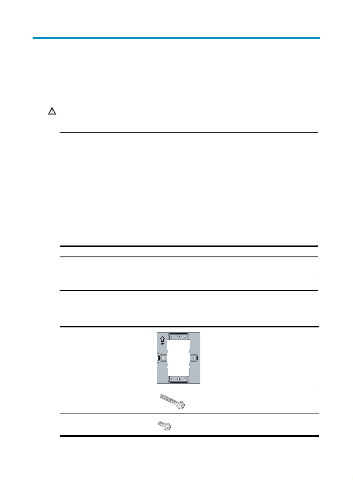
Accessories provided with the AP ···································································································································2
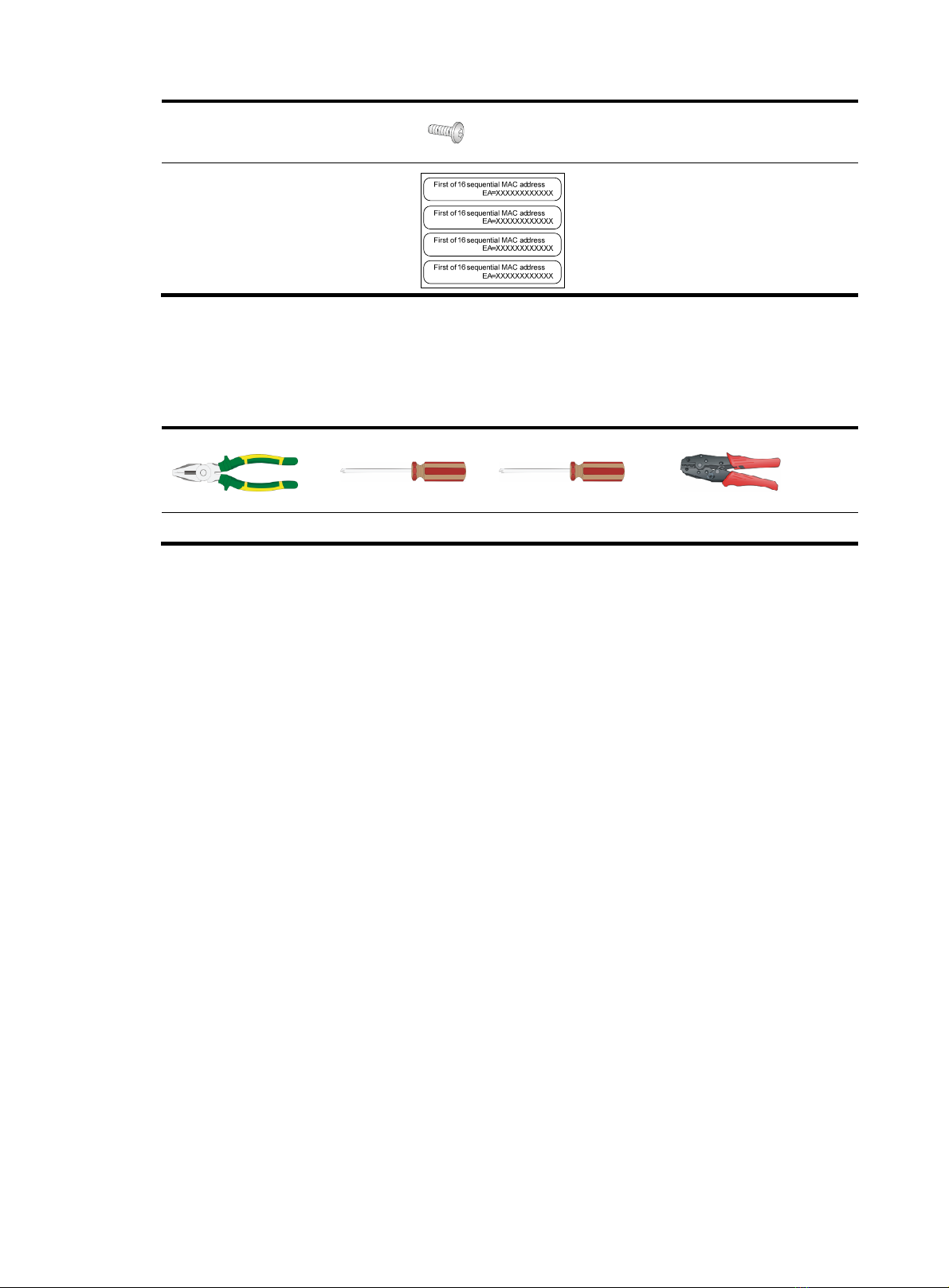
Installation tools and equipment······································································································································3
Installing the AP···························································································································································· 4
Check before installation··················································································································································4
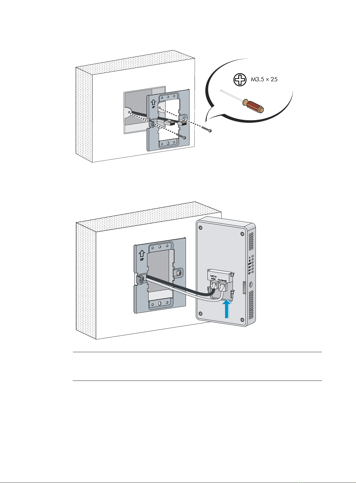
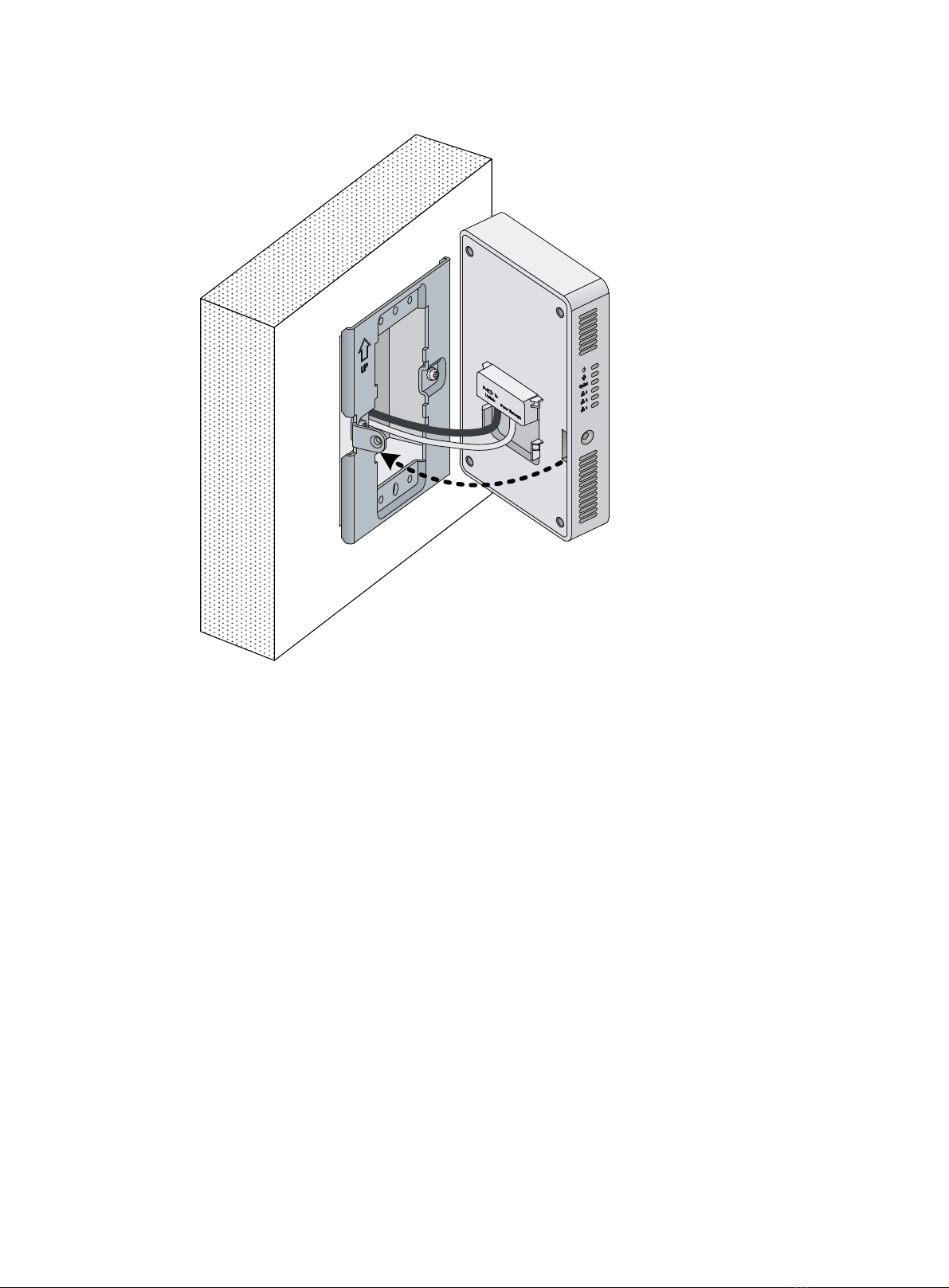
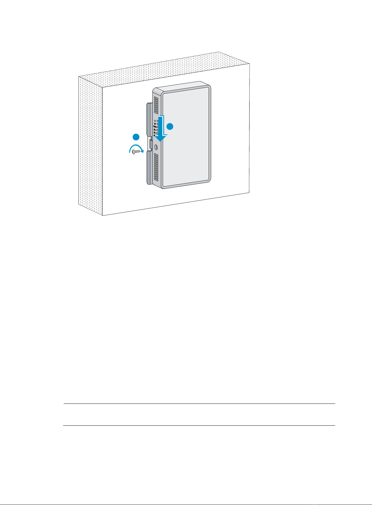
Installing the AP·································································································································································4
Connecting the AP to the power supply ·························································································································7
Check before power-on ···········································································································································7
Connecting PoE power supply································································································································7
Connecting local power supply ······························································································································7
Check after power-on···············································································································································8
Connecting the AP to the network···································································································································8
Verifying network connection for the fit AP ···········································································································9
Verifying network connection for the fat AP··········································································································9
Logging in to the AP···················································································································································10
Logging in through Telnet or Web ······························································································································· 10
Appendix LEDs and ports ··········································································································································11
LEDs ················································································································································································· 11
Ports ················································································································································································· 12
Index ···········································································································································································14


 installation guide")