HACH LANGE BUHLER 3010 How to use

DOC013.52.90205
BÜHLER 3010, 3900, 4010–4410
Short Manual
1/2017, Edition 3


3
Table of contents
Section 1 Specifications ........................................................................................................................5
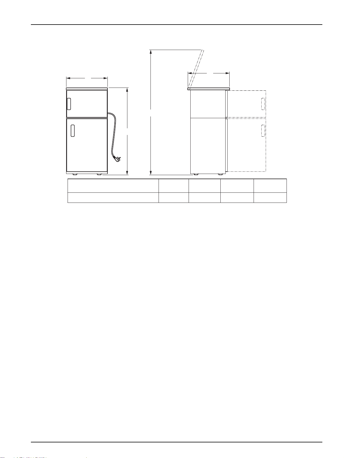
1.1 Dimensions ........................................................................................................................................6
Section 2 General information...............................................................................................................9
2.1 Safety information...............................................................................................................................9
2.1.1 Hazard information in this manual ............................................................................................. 9
2.1.2 Warning labels...........................................................................................................................9
2.2 General information..........................................................................................................................10
2.2.1 Areas of application ................................................................................................................. 10
2.2.2 Functional description..............................................................................................................10
2.3 Scope of delivery.............................................................................................................................. 10
Section 3 Installation............................................................................................................................ 13
3.1 Mechanical installation......................................................................................................................14
3.1.1 Required tools..........................................................................................................................14
3.1.2 Select installation location........................................................................................................15
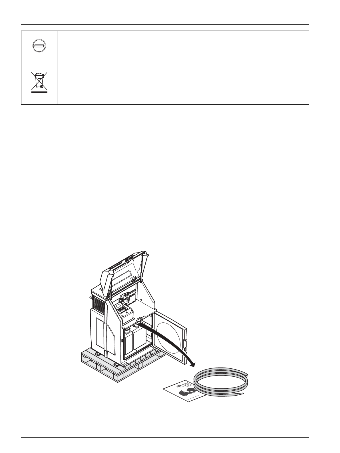
3.1.3 Unpacking................................................................................................................................16
3.1.4 Set up.......................................................................................................................................17
3.2 Electrical connections.......................................................................................................................19
3.2.1 Electrical installation ................................................................................................................20
3.2.1.1 Prepare the electrical installation (3010).........................................................................20
3.2.1.2 Prepare the electrical installation (3900–4410)...............................................................21
3.2.1.3 Wiring diagram (3010) ....................................................................................................22
3.2.1.4 Wiring diagram (3900–4410) ..........................................................................................22
3.2.1.5 Complete the electrical installation (3010)...................................................................... 23
3.2.1.6 Complete the electrical installation (3900–4410)............................................................23
3.3 Commission the equipment..............................................................................................................24
3.3.1 Tube connection......................................................................................................................24
3.3.2 Set the individual sample volumes...........................................................................................27
3.3.2.1 Plastic dosing vessel.......................................................................................................27
3.3.2.2 Glass dosing vessel........................................................................................................ 29
3.3.2.3 Dosing vessel for flow-proportional sampling .................................................................29
3.3.2.4 Bypass dosing vessel .....................................................................................................30
3.3.2.5 Flush water connection and drain (4210/4410)...............................................................31
3.3.3 Preparing the sample containers (3010, 3900, 4010, 4110, 4210)..........................................32
3.3.4 Connect the equipment to the mains.......................................................................................32

4
Section 4 Operation ..............................................................................................................................35
4.1 Control unit operation........................................................................................................................35
4.1.1 Password..................................................................................................................................35
4.1.2 Programming............................................................................................................................35
4.1.2.1 Keyboard layout/function.................................................................................................35
4.2 Normal operation...............................................................................................................................37
4.2.1 Replace the sample bottles (3010, 3900, 4010, 4110, 4211)...................................................38
4.2.2 Sampling (4411 with 12 or 24 bottles)......................................................................................40
4.2.3 Sampling (4411 with 2 or 4 bottles)..........................................................................................44
Section 5 Maintenance and cleaning...................................................................................................49
5.1 Maintenance tasks ............................................................................................................................49
5.2 Cleaning............................................................................................................................................49
5.2.1 Clean the housing and distribution unit ....................................................................................49
5.2.2 Clean the dosing vessel...........................................................................................................51
5.3 Troubleshooting ................................................................................................................................53
5.3.1 Open the housing to change the fuse (3010)...........................................................................53
5.3.2 Open the housing to change the fuse (3900–4410).................................................................54
5.3.3 Change the fuse.......................................................................................................................54
5.3.4 Reassemble the housing (3010) ..............................................................................................55
5.3.5 Reassemble the housing (3900–4410) ....................................................................................56
5.4 Instrument decommissioning and storage.........................................................................................56
Section 6 Spare parts and accessories ..............................................................................................57
6.1 Spare parts........................................................................................................................................57
Section 7 Warranty and liability...........................................................................................................61

5
Section 1 Specifications
Specifications are subject to change without notice.
Electrics
Power supply 230V/50Hz.,16Afuse
Power consumption approx. 350 VA
Environment
Medium temperature 0to+40°C[32to104°F]
Ambient temperature –20to+40°C[–4to104°F]
Delivery height < 8 m [26.2 ft}
General specifications
Maintenance requirements Maintenance-free
Weight See Figure 11, page 18
Dimensions (W × H × D) See Figure 1
Certification
Certification CE compliant, MCERTS (not 3010, 3900)
Sampling in accordance with ISO 5667-2/3-10

6
Specifications
1.1 Dimensions
Figure 1 Dimensions 3010, 4010 - 4410
5
jkl
6
mno
4
ghi
8
tuv wxyz
97
pqrs
2
abc
3
def
1
0
Y1
XZ
Y2
BÜHLER 3010
mm [in.]
Y1
1100 [43.3]
mm [in.]
X
760 [30]
mm [in.]
Y2
1640 [64.6]
mm [in.]
Z
725 [28.5]
BÜHLER 4210
BÜHLER 4410 (2–12 Flaschen)
BÜHLER 4210 (23 Flaschen)
BÜHLER 4110
1325 [52.2]
1325 [52.2]
1415 [55.7]
1475 [58.1]
605 [23.8]
605 [23.8]
715 [28.1]
605 [23.8]
1895 [74.6]
1895 [74.6]
2120 [83.5]
2030 [79.9]
BÜHLER 4010 1325 [52.2]605 [23.8] 1895 [74.6] 645 [25.4]
645 [25.4]
645 [25.4]
810 [31.9]
645 [25.4]
(23 bottles)
(2–12 bottles)
(24 bottles)

7
Specifications
Figure 2 Dimensions 3900
Y1
XZ
Y2
mm [in.]
Y1
mm [in.]
Xmm [in.]
Y2 mm [in.]
Z
BÜHLER 3900 1125 [44.3]625 [24.6] 1695 [66.7] 648 [25.5]

8
Specifications

9
Section 2 General information
2.1 Safety information
Please read this entire manual before the equipment is unpacked, set up or operated. Pay
attention to all danger and caution statements. Personal injury or damage to the
equipment could occur if they are not observed.
To ensure that the protection provided by this equipment is not impaired, do not use or
install this equipment in any manner other than that specified in this manual.
2.1.1 Hazard information in this manual
DANGER
Indicates a potentially or imminently hazardous situation which, if not avoided, will
result in death or serious injury.
WARNING
Indicates a potentially or imminently hazardous situation that, if not avoided, could
result in death or serious injury.
CAUTION
Indicates a potentially or imminently hazardous situation that could result in minor
or moderate injury.
Important note: Information that requires special emphasis.
Note: Information that supplements points in the main text.
2.1.2 Warning labels
Read all labels and notices attached to the equipment. Personal injury or damage to the
equipment could occur if they are not observed. Any symbol on the equipment will appear
along with a caution statement in the manual.
This symbol, if noted on the instrument, references the user manual for operation and/or safety information.
This symbol, when noted on a product enclosure or barrier, indicates that a risk of electrical shock and/or
electrocution exists.
This symbol may appear on the product and indicates the need for protective eye wear.
This symbol may appear on the product and identifies the connection point for the protective ground.

10
General information
2.2 General information
2.2.1 Areas of application
The equipment is used for sampling aqueous liquids with a temperature between 0°C
and 40°C [32 to 104 °F].
2.2.2 Functional description
The equipment provides temporary storage for liquids of a specified volume so that they
can be analyzed.
2.3 Scope of delivery
The equipment is supplied with a tube and a short manual.
If you require further information, you can order the operating instructions (refer to
Section 6 Spare parts and accessories, page 57) from the manufacturer or you can
download it from the Internet.
When this symbol appears on the product, it identifies the location of a fuse or a current limiter.
Electrical equipment marked with this symbol may not be disposed of in European domestic or public disposal
systems after 12 August 2005. In conformity with European local and national regulations (EU Directive
2002/96/EC), European electrical equipment users must now return old or end-of life equipment to the
manufacturer for disposal at no charge to the user.
Note: For return for recycling, please contact the equipment manufacturer or supplier for instructions on how
to return end-of-life equipment, manufacturer-supplied electrical accessories, and all auxiliary items for proper
disposal.
Figure 3 Scope of delivery (3010)

11
General information
Figure 4 Scope of delivery (3900–4410)

12
General information

13
Section 3 Installation
DANGER
Only qualified experts should conduct the tasks described in this section.
DANGER
Select an appropriate installation location for the instrument.
Plan out the mechanical mount·before positioning poles or drilling holes. Make
sure the mount has a sufficient bearing capacity. The dowels must be selected and
authorized according to the condition of the wall.
The manufacturer shall accept no liability if the instrument is installed incorrectly.
Plan how to lay cables and tubes and their path in advance. Lay the tubes, data
cables and power cables without any bends and so they do not pose a tripping
risk.
Do not connect the electrical supply to the mains if the equipment has not been
wired and fused correctly.
Sufficiently protect the electrical power supply against short circuits.
For the external power supply, always connect a residual-current circuit
breaker·(trip current max.: 30 mA) between the mains and the system.
If the equipment is to be installed outdoors, switch the overload protection
between mains and system.
Products intended by the manufacturer for outdoor use offer a higher level of
protection against the penetration of liquids and dust. If these products are
connected to a mains outlet with a cable and plug·rather than a permanently
connected cable, the plug and outlet are much more susceptible to liquid and dust
penetration. The operator must sufficiently protect the plug and outlet against
liquid and dust penetration in accordance with local safety regulations. If the
instrument is to be used outdoors, it must be connected to a suitable outlet with a
protection type of at least IP44 (splash protection).

14
Installation
3.1 Mechanical installation
DANGER
Select an appropriate installation location for the instrument.
Plan out the mechanical mount·before positioning poles or drilling holes. Make
sure the mount has a sufficient bearing capacity. The dowels must be selected and
authorized according to the condition of the wall.
The manufacturer shall accept no liability if the instrument is installed incorrectly.
Plan how to lay cables and tubes and their path in advance. Lay the tubes, data
cables and power cables without any bends and so they do not pose a tripping
risk.
Note: For information on installation with optional accessories, refer to the relevant installation
instructions.
3.1.1 Required tools
Figure 5 Required tools
17 mm

15
Installation
3.1.2 Select installation location
Figure 6 Select installation location
≥50mm
[2 in]≥
Z
Y2
5
jkl 6
mno
4
ghi
8
tuv wxyz
97
pqrs
2
abc 3
def
1
0
2500 mm
[100 in]
≥ 500 mm
[20 in]≥
≥ 500 mm
[20 in]≥
Y1
X
BÜHLER 3010
X
mm [in.]
760 [30]
Y1
mm [in.]
1100 [43.3]
mm [in.]
Y2
1640 [64.6]
mm [in.]
Z
725 [28.5]
BÜHLER 4010
BÜHLER 3900
BÜHLER 4210
BÜHLER 4410
(2–12 Flaschen)
BÜHLER 4210
(23 Flaschen)
BÜHLER 4410
(24 Flaschen)
BÜHLER 4110
605 [23.8]
605 [23.8]
715 [28.1]
605 [23.8]
715 [28.1]
605 [23.8]
1325 [52.2]
1325 [52.2]
1415 [55.7]
1325 [52.2]
1415 [55.7]
1475 [58.1]
1895 [74.6]
1895 [74.6]
2120 [83.5]
1895 [74.6]
2120 [83.5]
2030 [79.9]
645 [25.4]
625 [24.6] 1125 [44.3] 1695 [66.7] 648 [25.5]
645 [25.4]
810 [31.9]
645 [25.4]
810 [31.9]
645 [25.4]
Ex
(2–12 bottles)
(24 bottles)
(23 bottles)

16
Installation
3.1.3 Unpacking
Figure 7 Prepare the installation location
Ø12 × 60 mm
mm [in.]
A
730 [28.7]
B
mm [in.]
384 [15.1]
BÜHLER 3010
660 [26]
660 [26]
660 [26]
660 [26]
770 [30.3]
770 [30.3]
383 [15.1]
383 [15.1]
383 [15.1]
383 [15.1]
500 [19.7]
500 [19.7]
BÜHLER 4010
660 [26] 383 [15.1]
BÜHLER 3900
BÜHLER 4110
BÜHLER 4210
BÜHLER 4410
(2–12 Flaschen)
BÜHLER 4410
(23 Flaschen)
BÜHLER 4410
(24 Flaschen)
≥
(2–12 bottles)
(24 bottles)
(23 bottles)
Figure 8 Move the equipment from the transport pallet (3010)

17
Installation
3.1.4 Set up
Figure 9 Move the equipment from the transport pallet (3900–4410)
Figure 10 Set up the equipment (3010)
BÜHLER 3010
kg
75

18
Installation
Figure 11 Set up the equipment (3900, 4010-4410)
BÜHLER 4010
BÜHLER 3900 82
BÜHLER 4210
BÜHLER 4410
BÜHLER 4110
Figure 12 Align and secure the equipment
³Ø12×60mm
>80Nm
³17 mm

19
Installation
3.2 Electrical connections
DANGER
Only qualified experts should conduct the tasks described in this section.
DANGER
Do not connect the electrical supply to the mains if the equipment has not been
wired and fused correctly.
Sufficiently protect the electrical power supply against short circuits.
For the external power supply, always connect a residual-current circuit
breaker·(trip current max.: 30 mA) between the mains and the system.
If the equipment is to be installed outdoors, switch the overload protection
between mains and system.
If the mains plug·of the power supply cable·is removed, a suitable double-pole
one-way switch must be installed immediately next to the display unit·with clear
labeling for the power supply.
Products intended by the manufacturer for outdoor use offer a higher level of
protection against the penetration of liquids and dust. If these products are
connected to a mains socket with a cable and plug·rather than a permanently
connected cable, the plug and socket are much more susceptible to liquid and
dust penetration. The operator must sufficiently protect the plug and outlet against
liquid and dust penetration in accordance with local safety regulations. If the
instrument is to be used outdoors, it must be connected to a suitable outlet with a
protection type of at least IP44 (splash protection).

20
Installation
3.2.1 Electrical installation
3.2.1.1 Prepare the electrical installation (3010)
Figure 13 Loosen the screws and remove the cover (3010)
Figure 14 Feed cable through (3010)
This manual suits for next models
4
Table of contents
Other HACH LANGE Laboratory Equipment manuals
Popular Laboratory Equipment manuals by other brands

Agilent Technologies
Agilent Technologies G1701EA Getting started

Velp Scientifica
Velp Scientifica F206A0179 instruction manual

Bruker
Bruker 700'54 Ascend user manual

Thermo Scientific
Thermo Scientific Applied Biosystems QuantStudio 6 Pro user guide

GYROZEN
GYROZEN 1730R user manual

Healthmark
Healthmark FIS-007HB Instructions for use