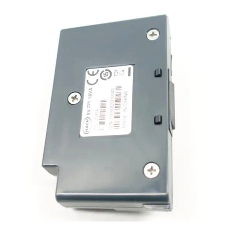
Hach SC4200c User manual

DOC273.98.90588
SC4200c Profibus Network
Module
01/2020, Edition 6
User Instructions
Bedienungsanleitung
Istruzioni per l'uso
Instructions d'utilisation
Instrucciones para el usuario
Instruções do utilizador
Návod pro uživatele
Gebruiksaanwijzingen
Brugervejledninger
Instrukcja obsługi
Bruksanvisning
Инструкции за потребителя
Felhasználói útmutató
Instrucţiuni de utilizare
Kullanma talimatları
Návod na použitie
Navodila za uporabo
Korisničke upute
Οδηγίες χρήσης

Table of Contents
English..............................................................................................................................3
Deutsch.......................................................................................................................... 20
Italiano............................................................................................................................ 37
Français......................................................................................................................... 54
Español.......................................................................................................................... 71
Português...................................................................................................................... 88
Čeština......................................................................................................................... 105
Nederlands................................................................................................................. 122
Dansk............................................................................................................................139
Polski............................................................................................................................ 156
Svenska....................................................................................................................... 173
български................................................................................................................... 190
Magyar......................................................................................................................... 207
Română....................................................................................................................... 224
Türkçe...........................................................................................................................241
Slovenský jazyk......................................................................................................... 258
Slovenski..................................................................................................................... 275
Hrvatski........................................................................................................................ 292
Ελληνικά...................................................................................................................... 309
2

Table of Contents
1 Specifications on page 3
2 General information on page 3
3 Installation on page 6
4 Configuration on page 17
5 Troubleshooting on page 17
Section 1 Specifications
Specifications are subject to change without notice.
Specification Details
Profibus protocol Siemens ASIC SPC3
DP service DPV0 slave
DP/DPV1 services DPV1 class 1 and class 2 slave
I&M function
Address changing per Profibus master
Profibus baud rates 9.6k, 19.2k, 45.45k, 93.75k, 187.5k, 500k, 1.5M, 3M, 6M, 12M
Automatic baud rate detection
Indicators LED to display the data exchange mode
Interface type RS485
Configurable parameters Data swapping, word wise for floating points values
Operating temperature -20 to 60 °C (-4 to 140 °F); 95% relative humidity, non-condensing
Storage temperature -20 to 70 °C (-4 to 158 °F); 95% relative humidity, non-condensing
Operating voltage 8 V to 16 V
Power consumption 2 W maximum
Wiring Wire gauge: 0.08 to 1.5 mm2 (28 to 16 AWG) with an insulation rating of 300 VAC or
higher1
Certification Listed for use with the SC4200c controller in Class 1, Division 2, Group A, B, C and D,
Zone 2, Group IIC hazardous locations to FM and CSA safety standards by ETL
Section 2 General information
In no event will the manufacturer be liable for direct, indirect, special, incidental or consequential
damages resulting from any defect or omission in this manual. The manufacturer reserves the right to
make changes in this manual and the products it describes at any time, without notice or obligation.
Revised editions are found on the manufacturer’s website.
2.1 Safety information
N O T I C E
The manufacturer is not responsible for any damages due to misapplication or misuse of this product including,
without limitation, direct, incidental and consequential damages, and disclaims such damages to the full extent
permitted under applicable law. The user is solely responsible to identify critical application risks and install
appropriate mechanisms to protect processes during a possible equipment malfunction.
1Do not use wire gauge other than 0.08 to 1.5 mm2 (28 to 16 AWG), unless wires can be isolated
from mains power and relay circuits.
English 3

Please read this entire manual before unpacking, setting up or operating this equipment. Pay
attention to all danger and caution statements. Failure to do so could result in serious injury to the
operator or damage to the equipment.
Make sure that the protection provided by this equipment is not impaired. Do not use or install this
equipment in any manner other than that specified in this manual.
2.1.1 Use of hazard information
D A N G E R
Indicates a potentially or imminently hazardous situation which, if not avoided, will result in death or serious injury.
WARNING
Indicates a potentially or imminently hazardous situation which, if not avoided, could result in death or serious
injury.
CAUTION
Indicates a potentially hazardous situation that may result in minor or moderate injury.
N O T I C E
Indicates a situation which, if not avoided, may cause damage to the instrument. Information that requires special
emphasis.
2.1.2 Precautionary labels
Read all labels and tags attached to the instrument. Personal injury or damage to the instrument
could occur if not observed. A symbol on the instrument is referenced in the manual with a
precautionary statement.
This symbol, if noted on the instrument, references the instruction manual for operation and/or safety
information.
This symbol indicates that a risk of electrical shock and/or electrocution exists.
This symbol indicates the presence of devices sensitive to Electro-static Discharge (ESD) and
indicates that care must be taken to prevent damage with the equipment.
Electrical equipment marked with this symbol may not be disposed of in European domestic or public
disposal systems. Return old or end-of-life equipment to the manufacturer for disposal at no charge to
the user.
2.1.3 Class 1 Division 2 label
CL 1 DIV 2 Gr A-D
See Manual
Voir manuel
This label indicates that the module is approved for use in a Class I Div 2 A-D, T4/ Class I
Zone 2 IIC, T4 environment when used with a Class I Div 2 approved SC4200c Controller and
sensors: LDO and TSS-Ex 1.
4 English

2.1.4 Precautions for hazardous location installation
D A N G E R
Explosion hazard. Only qualified personnel should conduct the installation tasks described in this
section of the manual. This equipment is suitable for use in Class 1, Division 2, Groups A, B, C & D
Hazardous Locations with specified sensors and options appropriately certified and rated for Class I,
Division 2, Group A, B, C & D , Zone 2, Group IIC Hazardous Locations.
D A N G E R
Explosion hazard. Do not remove or replace modules while power is supplied to the controller unless
there are no ignitable gases in the area.
D A N G E R
Explosion hazard. Do not connect or disconnect electrical components or circuits to the equipment
unless power has been removed or the area is known to be non-hazardous.
D A N G E R
Explosion hazard. Connect only peripheral components that are clearly marked as certified for Class
1, Division 2 Hazardous Locations.
Never connect any sensor or digital or analog module to an SC Controller that is not clearly marked
as certified for Class 1, Division 2 Hazardous Locations.
2.2 Product overview
The sc controllers are the platform for all intelligent probes and analyzers. The sc platform is a fully
digital communication system based on the open Modbus standard.
When a Profibus network module is installed, the sc controllers can be configured to give the full
range of standardized method values and parameters.
The controller is compatible with master class 1 (PLC SCADA) and master class 2 systems, e.g.,
engineering stations.
An overview of the system is shown in Figure 1.
Figure 1 System overview
1 sc controller (Slave) 3 PC with software (Master class 2 e.g., PC with
CP5611 card installed)
2 Programmable logic controller (Master class 1)
English 5

2.3 Product components
Make sure that all components have been received. Refer to Product components on page 6. If any
items are missing or damaged, contact the manufacturer or a sales representative immediately.
Figure 2 Product components
1 Module connector 4 Label with wiring information
2 Profibus module 5 Screwdriver, 2-mm wide blade
3 Hardware for shield connection to the controller
enclosure
Section 3 Installation
D A N G E R
Multiple hazards. Only qualified personnel must conduct the tasks described in this section of the
document.
D A N G E R
Electrocution hazard. Remove power from the instrument before this procedure is started.
D A N G E R
Electrocution hazard. High voltage wiring for the controller is conducted behind the high voltage
barrier in the controller enclosure. The barrier must remain in place unless a qualified installation
technician is installing wiring for power, alarms, or relays.
WARNING
Electrical shock hazard. Externally connected equipment must have an applicable country safety
standard assessment.
N O T I C E
Make sure that the equipment is connected to the instrument in accordance with local, regional and national
requirements.
6 English

3.1 Electrostatic discharge (ESD) considerations
N O T I C E
Potential Instrument Damage. Delicate internal electronic components can be damaged by static
electricity, resulting in degraded performance or eventual failure.
Refer to the steps in this procedure to prevent ESD damage to the instrument:
• Touch an earth-grounded metal surface such as the chassis of an instrument, a metal conduit or
pipe to discharge static electricity from the body.
• Avoid excessive movement. Transport static-sensitive components in anti-static containers or
packages.
• Wear a wrist strap connected by a wire to earth ground.
• Work in a static-safe area with anti-static floor pads and work bench pads.
3.2 Install the module
Install the module in the controller. Refer to the illustrated steps that follow.
The illustrated steps shows how to connect Profibus network modules to each other in a chain as
follows:
• Wires are installed in the two input terminals (1 and 2) and the two output terminals (5 and 6) of
the first Profibus module. Refer to step 11 of the illustrated steps.
• The two output terminal wires in the first profibus module are installed in the two input terminals
(1 and 2) of the second Profibus module (end of the network) to continue communication on the
network, including any information from the input signals.
• The "T" switch on the first Profibus module is set to the down (non-terminated) position. Refer to
step 9 of the illustrated steps.
• The "T" switch on the second Profibus module is set to up (terminated) position.
Note: To use a Profibus network card alone, install the wires only in the input terminals (1 and 2) and set the "T"
switch to the up (terminated) position.
To keep the enclosure rating, make sure that all unused electrical access holes are sealed with an
access hole cover.
English 7

8 English

English 9

10 English

N O T I C E
Use cabling with a wire gauge of 0.08 to 1.5 mm2 (28 to 16 AWG)2 and an insulation rating of 300 VAC or higher.
Use twisted-pair shielded wire3.
2Do not use wire gauge other than 0.08 to 1.5 mm2 (28 to 16 AWG), unless wires can be isolated
from mains power and relay circuits.
3Use of non-shielded cable may result in radio frequency emission or susceptibility levels higher
than allowed.
English 11

12 English

English 13

Table 1 Wiring information
Terminal Signal Color Description
1 A1 (input) Green Input to the module
2 B1 (input) Red Input to the module
3 0 V — Not used
4 5 V — Not used
5 A2 (output) Green Output from the module
6 B2 (output) Red Output from the module
14 English

English 15

16 English

Section 4 Configuration
1. Open an internet browser.
2. Enter the applicable URL that follows to start the software:
•US: https://us.fsn.hach.com
•EU: https://eu.fsn.hach.com
3. Enter the login information.
4. Configure the Profibus settings to select the data order, data structure and device order. Refer to
the SC4200c Controller documentation for instructions.
4.1 IEEE 745 floating point definition
Profibus uses 32-bit single precision IEEE floating point definition. The definition has twenty three
bits for the mantissa and eight bits for the exponent. There is one bit for the sign of the mantissa.
Refer to Figure 3.
Figure 3 Floating point definition
1 Sign bit 4 Exponent
2 Exponent 5 Mantissa
3 Mantissa
4.2 Word wise swapping
In word wise swapping, the third and fourth bytes are interchanged in order with the first and second
bytes. This results in a byte order of 3 4 1 2. The byte order complies to the IEEE Big Endian floating
point definition.
Section 5 Troubleshooting
WARNING
Multiple hazards. Do not disassemble the instrument for maintenance. If the internal components
must be cleaned or repaired, contact the manufacturer.
5.1 Error and status indicators
Error and status words follow the same standard definition for all sc probes and controllers.
Table 2 lists bit position and error messages. Table 3 lists bit position and status messages.
A bit value of zero shows the error or status condition that is not true.
English 17

A bit value of 1 shows the error or status condition that is true. For example, if Bit 0 has the value of
1, an error has occurred during the last calibration.
Table 2 Error messages
Bit Message Indication
0 Measurement calibration error An error has occurred during the last calibration
1 Electronic adjustment error An error has occurred during the last electronic calibration
2 Cleaning error The last cleaning cycle failed
3 Measuring module error A failure has been detected in the Measurement Module
4 System re-initialization error Some settings are inconsistent and have been reset to factory
defaults
5 Hardware error A general hardware error has been detected
6 Internal communication error A communication failure within the device has been detected
7 Humidity error Excessive humidity has been detected within the device
8 Temperature error Temperature within the device exceeds a specified limit
9 — —
10 Sample warning Some action is required with the sample system
11 Questionable calibration warning The last calibration may not be accurate
12 Questionable measurement warning One or more of the device measurements are out of range or are of
questionable accuracy
13 Safety warning A condition has been detected which may result in a safety hazard
14 Reagent warning The reagent system requires attention
15 Maintenance required warning The device requires maintenance
Table 3 Status indicator messages
Bit Message Indication
0 Calibration in progress The device is in a calibration mode. Measurements may not be valid.
1 Cleaning in progress The device is in a cleaning mode. Measurements may not be valid.
2 Service/Maintenance menu The device is in a service or maintenance mode. Measurements may not be
valid.
3 Common error The device has recognized an error. See Error Register for Error Class.
4 Measurement 0 Quality Bad Precision of measurement is out of specified limits.
5 Measurement 0 Low Limit Measurement is below the specified range.
6 Measurement 0 High Limit Measurement is above the specified range.
7 Measurement 1 Quality Bad Precision of measurement is out of the specified limits.
8 Measurement 1 Low Limit Measurement is below the specified range.
9 Measurement 1 High Limit Measurement is above the specified range.
10 Measurement 2 Quality Bad Precision of measurement is out of the specified limits.
11 Measurement 2 Low Limit Measurement is below the specified range.
12 Measurement 2 High Limit Measurement is above the specified range.
18 English

Table 3 Status indicator messages (continued)
Bit Message Indication
13 Measurement 3 Quality Bad Precision of measurement is out of the specified limits.
14 Measurement 3 Low Limit Measurement is below the specified range.
15 Measurement 3 High Limit Measurement is above the specified range.
5.2 Event Log
Refer to Table 4 for diagnostic device information.
Table 4 Event log
Event Description
ADDRESS Adjusted Profibus address
DATA ORDER Indicates the data order of 2 word variables in the cyclic and acyclic Profibus telegram
SIMULATION Indicates if the simulated data is set into the cyclic Profibus telegram.
SENSOR POWER Timestamp of the Profibus card power up
SET DATE/TIME Setup timestamp of the internal timer of the Profibus card
NEW CONFIG Timestamp of a new configuration
AUTO CONFIGURE Timestamp of a new menu setting
CODE VERSION Timestamp of a new software download (Software version)
English 19

Inhaltsverzeichnis
1 Technische Daten auf Seite 20
2 Allgemeine Informationen auf Seite 20
3 Installation auf Seite 23
4 Konfiguration auf Seite 34
5 Fehlerbehebung auf Seite 34
Kapitel 1 Technische Daten
Änderungen vorbehalten.
Technische Daten Details
Profibus-Protokoll Siemens ASIC SPC3
DP-Dienst DPV0-Slave
DP/DPV1-Dienste DPV1-Slave Klasse 1 und Klasse 2
I&M-Funktion
Adressänderung per Profibus-Master
Profibus-Baudraten 9,6 k, 19,2 k, 45,45 k, 93,75 k, 187,5 k, 500 k, 1,5 M, 3 M, 6 M, 12 M
Automatische Baudratenerkennung
Anzeigen LED zur Anzeige des Datenaustauschmodus
Schnittstellentyp RS485
Konfigurierbare Parameter Datenfolge, Wortblocktausch für Gleitpunktwerte
Betriebstemperatur -20 bis 60 °C (-4 bis 140 °F); 95 % relative Feuchtigkeit, nicht kondensierend
Lagertemperatur -20 bis 70 °C (-4 bis 158 °F); 95 % relative Feuchtigkeit, nicht kondensierend
Betriebsspannung 8 V bis 16 V
Leistungsaufnahme 2 W Maximum
Verdrahtung Leiterquerschnitt: 0,08 bis 1,5 mm2 (AWG 28 bis 16) mit einer Nennisolierung von
300 V Wechselstrom oder höher1
Zertifizierung FM- und CSA-Zulassung für den Einsatz mit dem SC4200c Controller für gefährliche
Standorte der Klasse 1, Unterteilung 2, Gruppen A, B, C und D, Zone 2, Gruppe IIC
durch ETL
Kapitel 2 Allgemeine Informationen
Der Hersteller ist nicht verantwortlich für direkte, indirekte, versehentliche oder Folgeschäden, die
aus Fehlern oder Unterlassungen in diesem Handbuch entstanden. Der Hersteller behält sich
jederzeit und ohne vorherige Ankündigung oder Verpflichtung das Recht auf Verbesserungen an
diesem Handbuch und den hierin beschriebenen Produkten vor. Überarbeitete Ausgaben der
Bedienungsanleitung sind auf der Hersteller-Webseite erhältlich.
1Verwenden Sie keinen anderen Leiterquerschnitt als einen von 0,08 bis 1,5 mm2 (AWG 28 bis
16), außer die Leiter können von der Stromversorgung und den Relaisschaltkreisen getrennt
werden.
20 Deutsch
Other manuals for SC4200c
4
Table of contents
Languages:
Other Hach Control Unit manuals
Popular Control Unit manuals by other brands

Nordson EFD
Nordson EFD 752V-HL operating manual

NOVA Swiss
NOVA Swiss NV Series Repair instructions

Ogden
Ogden ETR-9040 instruction manual

Dakota Digital
Dakota Digital VFD III Series quick start guide

Power integrations
Power integrations Scale-2 1SC0450E2B0 Applications manual

GSD
GSD WXT2CM2511 quick start guide

GE
GE VersaMax IC200ALG630 manual

salmson
salmson Cleanskid Series Installation and starting instructions

Allen-Bradley
Allen-Bradley 1440-DYN02-01RJ user manual

United Electronic Industries
United Electronic Industries DNx-AO-308-353 user manual

SimCom
SimCom SIM5300E AT Command manual

Zurn Wilkins
Zurn Wilkins 375 Installation, Testing, Maintenance Instructions