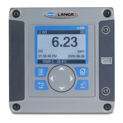
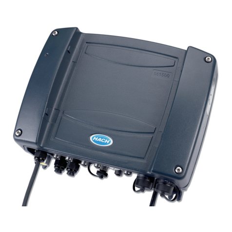
Hach sc1000 User manual

Catalog Number DOC023.54.03260
sc1000 Controller
USER MANUAL
February 2005 Edition 1
©Hach Company, 2005. All rights reserved. Printed in the U.S.A.
02/05 eac/dp
客服:400 688 9809
网址:www.mamots.com 电话:0431-85178766

3
Table of Contents
Section 1 Specifications......................................................................................................................................... 5
Section 2 General Information............................................................................................................................... 7
2.1 Safety Information............................................................................................................................................... 7
2.1.1 Use of Hazard Information......................................................................................................................... 7
2.1.2 Precautionary Labels................................................................................................................................. 7
2.2 General Product Information............................................................................................................................... 7
2.3 Controller Storage............................................................................................................................................... 8
Section 3 Installation.............................................................................................................................................. 9
3.1 Mechanical Installation........................................................................................................................................ 9
3.1.1 Controller Dimensions ............................................................................................................................. 10
3.2 Mounting the Controller..................................................................................................................................... 11
3.2.1 Wall Mounting the Controller ................................................................................................................... 11
3.2.2 Horizontal and Vertical Pipe Mounting..................................................................................................... 11
3.3 Wiring Safety Information.................................................................................................................................. 13
3.3.1 Electrostatic Discharge (ESD) Considerations........................................................................................ 13
3.4 Electrical Installation......................................................................................................................................... 14
3.4.1 Installation in Hard-wired Applications..................................................................................................... 14
3.4.2 Installation Using a Power Cord .............................................................................................................. 14
3.4.3 Wiring for AC Power at the Controller...................................................................................................... 17
3.4.4 Installing Power Outlets .......................................................................................................................... 19
3.4.5 Wiring for 24 VDC Power at the Controller.............................................................................................. 21
3.5 DIN-Rail Expansion Modules............................................................................................................................ 22
3.6 Expansion Card Connections ........................................................................................................................... 23
3.6.1 Relay Card Connections.......................................................................................................................... 24
3.6.2 Input Card Connections........................................................................................................................... 26
3.7 Output Card Connections ................................................................................................................................. 27
3.8 Modbus Card Connections................................................................................................................................ 28
3.9 Profibus DP Card Connections......................................................................................................................... 29
3.10 Removing an Expansion Card ........................................................................................................................ 30
3.11 Installing the sc1000 Network System............................................................................................................ 30
3.11.1 sc1000 Network Connections................................................................................................................ 30
3.12 Connecting Sensors to the sc1000................................................................................................................. 35
3.12.1 Connecting the Sensor Data Cable....................................................................................................... 35
3.12.2 Adding Sensor Connections.................................................................................................................. 35
3.13 Connecting AC Powered sc-Sensors.............................................................................................................. 36
Section 4 Commissioning.................................................................................................................................... 37
Section 5 Operation.............................................................................................................................................. 39
5.1 Using the Display Module ................................................................................................................................. 39
5.1.1 Attaching the Display Module to the Probe Module................................................................................. 39
5.1.2 Display Features...................................................................................................................................... 40
5.1.2.1 Using the Pop-up Toolbar.............................................................................................................. 40
5.1.2.2 Using the Device List ..................................................................................................................... 41
5.1.3 Using the Menu Windows........................................................................................................................ 42
5.1.3.1 Navigating the Menu Windows....................................................................................................... 42
5.1.4 Adjusting the Measured Value Display.................................................................................................... 44
5.1.4.1 Select Sensors for the Measured Value Display............................................................................ 45
5.1.5 Adjusting the Touch Screen Calibration................................................................................................... 45
5.1.6 Setting the Displayed Language.............................................................................................................. 46
5.1.7 Setting the Time and Date....................................................................................................................... 46
5.2 Sensor Status Menu.......................................................................................................................................... 46
客服:400 688 9809
网址:www.mamots.com 电话:0431-85178766
4
Table of Contents
5.3 Sensor Setup Menu...........................................................................................................................................46
5.4 System Setup Menu..........................................................................................................................................47
5.4.1 Output Setup............................................................................................................................................47
5.4.2 Current Inputs Setup................................................................................................................................48
5.4.3 Relay Setup..............................................................................................................................................49
5.4.4 Network Modules .....................................................................................................................................50
5.4.5 Device Management ................................................................................................................................51
5.4.6 Display Settings .......................................................................................................................................51
5.4.7 Browser Access .......................................................................................................................................51
5.5 Test/Maint Menu................................................................................................................................................52
5.5.1 Datalog Setup ..........................................................................................................................................52
5.5.2 Output Setup............................................................................................................................................52
5.5.3 Current Inputs ..........................................................................................................................................52
5.5.4 Relay........................................................................................................................................................52
5.5.5 Network Modules .....................................................................................................................................52
5.5.6 Display Info ..............................................................................................................................................52
5.6 Service Interface................................................................................................................................................53
5.6.1 Data Logger Option..................................................................................................................................53
5.6.2 Erasing Loggers.......................................................................................................................................53
5.6.3 Connecting a PC to the sc1000 ...............................................................................................................53
5.7 Configuring New Components...........................................................................................................................54
Section 6 Maintenance..........................................................................................................................................55
6.1 General Maintenance ........................................................................................................................................55
6.1.1 Fuse Replacement...................................................................................................................................55
Section 7 Replacement Parts and Accessories..................................................................................................57
7.1 Plug-in Expansion Cards...................................................................................................................................57
7.2 External DIN-Rail Mount Modules.....................................................................................................................57
7.3 Internal Network Components...........................................................................................................................57
7.4 Accessories.......................................................................................................................................................57
Section 8 How to Order.........................................................................................................................................59
Section 9 Repair Service.......................................................................................................................................60
Section 10 Limited Warranty ................................................................................................................................61
Section 11 Compliance Information ....................................................................................................................63
客服:400 688 9809
网址:www.mamots.com 电话:0431-85178766

5
Section 1 Specifications
Specifications are subject to change without notice.
Table 1 Display Module
Component Description Display module for menu-based operation
Enclosure Plastic housing, enclosure rating IP65
Screen Display QVGA, 320 x 240 pixels, 256 colors, touchscreen
Operating Temperature –20 to 55 °C (–4 to 131 °F); 95 % relative humidity, non-condensing
Storage Temperature –20 to 70 °C (–4 to 158 °F); 95 % relative humidity, non-condensing
Weight Approximately 1.2 kg
Dimensions 200 × 230 × 50 mm (7.9 × 9 × 2 inches)
Table 2 Probe Module
Component Description Probe module for the connection of sc sensors and power supply
Enclosure Metal housing with corrosion-resistant surface finish, IP65 rating
Power Requirements 100–240 V ± 10 VAC, 50 / 60 Hz, max. 2000 VA, Category II or 24 VDC (18–30 VDC), max.
75 W
Sensor Inputs (optional)14, 6, or 8 sensors. All parameters can be configured and combined as required.
Measuring Range Dependent on sensor.
Operating Temperature –20 to 55 °C (–4 to 131 °F); 95 % relative humidity, non-condensing
Storage Temperature –20 to 70 °C (–4 to 158 °F); 95 % relative humidity, non-condensing
Weight Approximately 5 kg, depending on configuration
Optional Expansions Analog Outputs, Analog/Digital Inputs, Relays, Digital Field-buses
Dimensions Without display module: 315 × 255 × 120 mm (12.4 × 10.1 × 4.8 inches)
With display module: 315 × 255 × 150 mm (12.4 × 10.1 × 6 inches)
Fuse Ratings 100–240 VAC: F1, F2: M 3,5 A (medium slow-blow); F3, F4: T 8 A; 100–240 V
24 VDC: 1 fuse, T 6,3 A; 24 VDC
sc1000 Network Cable
Shielded control cable with 2 cores, 24 AWG, stranded, CU wire
Characteristics impedance at 1 KHz > 100 W, wire color: white and blue
Outer sheath of the cable is UV and water resistant
External diameter of cable is 3.5–5 mm
1When installing additional sensors, observe the maximum total power of the system. Only two 1720E Turbidity instruments
can be used simultaneously on an sc1000 probe module.
客服:400 688 9809
网址:www.mamots.com 电话:0431-85178766

6
Specifications
Table 3 Plug-in Expansion Cards
Component Description Plug-in expansion cards for installation in the probe module
Operating Temperature –20 to 55 °C (–4 to 131 °F); 95% relative humidity, non-condensing
Storage Temperature –20 to 70 °C (–4 to 158 °F); 95% relative humidity, non-condensing
Analog Output Card 4 x analog current outputs (0–20 mA or 4–20 mA, max. 500 Ohm) Terminals max. 1.5 mm2
Analog/Digital Input Card 4 x analog/digital inputs (0–20 mA or 4–20 mA) Terminals max. 1.5 mm2
Internal Relay Card
4 x normally closed contacts (UL, SPST-NC, normally closed) Terminals max. 1.5 mm2
Maximum switching voltage: 250 VAC, 125 VDC
Nominal Switching Current: 250 VAC, 5 A; 125 VAC, 5 A, 125 VDC, 0.15 A; 30 VDC, 5 A
Fieldbus Interface Card Modbus (RS485) or Profibus DP
Table 4 DIN Rail Switch Cabinet Expansion Modules
Function For installation in the switch cabinet. Any expansions required can be combined when a base
module is available.
Enclosure Rating IP20
Power Supply 24 VDC (max. 30 V) from base module
Operating Temperature 4 to 40 °C (39 to 104 °F); 95% relative humidity, non-condensing
Storage Temperature –20 to 70 °C (–4 to 158 °F); 95% relative humidity, non-condensing
Base Module (LZX915)
Supply of expansion modules with 24 VDC and connection to the sc1000 network
Setting terminating resistor (with DIP switch) for the sc1000 network
Provision of connection for a display module (LXV402) for the configuration of the system
Current Consumption: Max. 2000 mA
Dimensions: 23 x 100 x 115 mm (1 x 4 x 4.5 in.)
Relay Module (LZX920)
4 x change over contacts
Current Consumption 100 mA
Maximum Switching Voltage: 250 VAC, 125 VDC
Nominal Switching Current:
250 VAC, 5 A; 125 VAC, 5 A; 125 VDC, 0.15 A; 30 VDC, 5 A
Can be programmed for limit, status or for timer, status indication by LED
Terminals max. 2.5 mm2
Dimensions: 45 x 100 x 115 mm (2 x 4 x 4.5 in.)
Output Module (LZX919) 2 analog current outputs (0–20 mA or 4–20 mA, max. 500 Ohm)
Terminals max. 2.5 mm2
Dimensions: 23 x 100 x 115 mm (1 x 4 x 4.5 in.)
Input Module
Analog/Digital inputs (can be programmed as 0–20 mA or 4–20 mA), INPUT or digital INPUT
Internal resistance: 180 Ohm
Terminals max. 2.5 mm2
Dimensions: 23 x 100 x 115 mm (1 x 4 x 4.5 in.)
客服:400 688 9809
网址:www.mamots.com 电话:0431-85178766
7
Section 2 General Information
2.1 Safety Information
Please read this entire manual before unpacking, setting up, or operating this equipment.
Pay attention to all danger and caution statements. Failure to do so could result in serious
injury to the operator or damage to the equipment.
To ensure that the protection provided by this equipment is not impaired, do not use or
install this equipment in any manner other than that specified in this manual.
2.1.1 Use of Hazard Information
DANGER
Indicates a potentially or imminently hazardous situation which, if not avoided,
could result in death or serious injury.
CAUTION
Indicates a potentially hazardous situation that may result in minor or
moderate injury.
Important Note: Information that requires special emphasis.
Note: Information that supplements points in the main text.
2.1.2 Precautionary Labels
Read all labels and tags attached to the instrument. Personal injury or damage to the
instrument could occur if not observed
2.2 General Product Information
The sc1000 is a multi-parameter controller designed to function with any of the digital
sensor family. A stand-alone sc1000 controller consists of one display module and one
probe module. The probe module can be configured to accept up to 8 digital sensors.
More sensors can be connected by creating an sc1000 network. An sc1000 network
consists of one display module and two or more probe modules. Each probe module can
be configured to accept up to 8 sensors each.
Each probe module can also be configured with relays, analog outputs, analog or digital
inputs, and digital field-bus cards.
This symbol, if noted on the instrument, references the instruction manual for operation and/or safety information.
This symbol, when noted on a product enclosure or barrier, indicates that a risk of electrical shock and/or
electrocution exists.
This symbol, if noted on the product, indicates the need for protective eye wear.
This symbol, when noted on the product, identifies the location of the connection for Protective Earth (ground).
This symbol, when noted on the product, identifies the location of a fuse or current limiting device.
客服:400 688 9809
网址:www.mamots.com 电话:0431-85178766
8
General Information
2.3 Controller Storage
When storing the sc1000 controller, ensure that all important data is saved. Remove
power and disconnect all connections from the system. Remove the probe module from its
mounting. Store the probe module and display module in a protective film or dry cloth in a
dry place.
客服:400 688 9809
网址:www.mamots.com 电话:0431-85178766

9
Section 3 Installation
DANGER
Only qualified personnel should conduct the tasks described in this section of
the manual.
3.1 Mechanical Installation
Figure 1 Probe Module with Display Module
1. Probe module 3. Display module
2. LED Indicator 4. Connector, Display Module to Probe Module
sc1000
3
1
2
4
客服:400 688 9809
网址:www.mamots.com 电话:0431-85178766

10
Installation
3.1.1 Controller Dimensions
Figure 2 sc1000 Controller Dimensions
sc1000
sc1000
315 mm (12.28 inches)
150 mm
(5.85 inches)
120 mm
(4.68 inches)
242 mm
(9.50 inches)
50 mm
(2.00 inches)
242 mm
(9.50 inches)
200 mm (7.80 inches)
客服:400 688 9809
网址:www.mamots.com 电话:0431-85178766

11
Installation
3.2 Mounting the Controller
The optional sun-shield is highly recommended for all outdoor installation. Refer to the
instruction sheet supplied with the sun shield for installation instructions.
3.2.1 Wall Mounting the Controller
Leave a minimum of 5 cm (2 in.) of space at the top and sides for cooling purposes and
display module installation. Leave a minimum of 15 cm (6 inches) of space underneath for
the cable connections. Refer to Figure 3 for proper wall mounting dimensions.
1. Install the four supplied bolts into the wall.
2. Hang the sc1000 controller system over the bolts and attach the supplied washers
and hand-tighten the two bottom bolts.
Figure 3 sc1000 Controller Mounting Features
3.2.2 Horizontal and Vertical Pipe Mounting
Refer to Figure 4 and Figure 5 on page 12 for mounting descriptions. For more information
on pipe mounting refer to the instructions supplied with the mounting kit.
315 mm (12.28 inches)
255 mm (9.94 inches)
254 mm (10.00 inches)
80 mm
(3.16 inches)
203 mm (8.00 inches)
80 mm
(3.16 inches)
6.7 mm
( 0.26 inches) (4)
M6 x 12.5 mm
(M6 x 0.5 inches)
50 mm (2.0 inches)
minimum clearance
客服:400 688 9809
网址:www.mamots.com 电话:0431-85178766

12
Installation
Figure 4 Pipe Mounting Hardware
Figure 5 Pipe Mounting the sc1000 Controller
1. Bracket, pipe mount
(Cat. No. LZY001) 2. Rubber pads (8)
(Cat. No. LZX948) 3. Flat washer, (4)
(Cat. No. LZX948) 4. Hexagon head screw (4) M5 x
30 mm (Cat. No. LZX948)
1. Probe module 4. Bracket, pipe mounting
2. Horizontal Pipe (customer-supplied, size may vary) 5. Hex head screw and flat washer
3. Vertical Pipe (customer-supplied, size may vary) 6. Rubber pads, (apply to the bracket and/or sun shield)
1234
1
1
4
4
5
6
6
5
2
3
客服:400 688 9809
网址:www.mamots.com 电话:0431-85178766

13
Installation
3.3 Wiring Safety Information
DANGER
Always disconnect power to the instrument when making electrical connections.
When making any wiring connections to the sc1000 Controller, the following warnings and
notes must be adhered to, as well as any warnings and notes found throughout the
individual installation sections. For more safety information refer to Safety Information on
page 7.
Remove the display module before performing any wiring tasks (Figure 6).
Figure 6 Remove Display Module and Probe Module Cover
3.3.1 Electrostatic Discharge (ESD) Considerations
Important Note: To minimize hazards and ESD risks, maintenance procedures not
requiring power to the analyzer should be performed with power removed.
Delicate internal electronic components can be damaged by static electricity, resulting in
degraded instrument performance or eventual failure. The manufacturer recommends
taking the following steps to prevent ESD damage to your instrument:
•Before touching any instrument electronic components (such as printed circuit cards
and the components on them) discharge static electricity from your body. This can be
accomplished by touching an earth-grounded metal surface such as the chassis of an
instrument, or a metal conduit or pipe.
•To reduce static build-up, avoid excessive movement. Transport static-sensitive
components in anti-static containers or packaging.
•To discharge static electricity from your body and keep it discharged, wear a wrist
strap connected by a wire to earth ground.
•Handle all static-sensitive components in a static-safe area. If possible, use anti-static
floor pads and work bench pads.
1. Display Module 3. Probe Module Cover
2. Connector, Display Module 4. Screw, (4)
1
sc1000
3
4
2
客服:400 688 9809
网址:www.mamots.com 电话:0431-85178766

14
Installation
3.4 Electrical Installation
DANGER
Only qualified personnel should conduct the installation tasks described in this
section of the manual.
DANGER
Always install a residual current circuit breaker (rccb) with a maximum trigger
current of 30 mA. If installed outside, provide overvoltage protection.
If installed outdoors, provide overvoltage protection between the power and the sc1000
controller system. Make sure the data and power cables do not cause tripping and do not
contain any sharp bends. Refer to Figure 8 for housing breakout information.
High-voltage wiring for the controller is conducted behind the high voltage barrier in the
controller enclosure. The barrier must remain in place unless a qualified installation
technician is installing wiring for power, alarms, or relays. See Figure 9 for barrier removal
information.
The instrument can be wired for line power by hard-wiring in conduit or by wiring to a
power cord if allowed by local electrical code. A local disconnect designed to meet local
electrical code is required and must be identified for all types of installation. See Figure 10
and Figure 11 on page 16 and for suggested local disconnect configurations.
Do not connect the electrical power supply to the AC power until the sc1000 controller
system has been fully wired, fused, and the high voltage barrier and probe module cover
have been replaced.
3.4.1 Installation in Hard-wired Applications
In hard-wired electrical applications, the power and safety ground service drops for the
instrument must be 18 to 12 AWG. A sealing-type strain relief must be used to maintain
the IP65 environmental rating. See Figure 7 on page 14 for strain relief and conduit
opening sealing plug assembly. See Figure 10 on page 16 for wiring information.
3.4.2 Installation Using a Power Cord
A sealing-type strain relief to maintain the IP65 environmental rating and a power cord
less than 3 meters (10 feet) in length with three 18-gauge conductors (including a safety
ground wire) can be used, see Replacement Parts and Accessories on page 57. See
Figure 7 for strain relief and conduit opening sealing plug assembly. See Figure 11 on
page 16 for wiring information.
Figure 7 Using the Optional Strain Relief and Conduit Plug
1. Strain Relief, small 2. Strain Relief, large 3. Conduit 4. Plug, sealing
12
4
3
客服:400 688 9809
网址:www.mamots.com 电话:0431-85178766
15
Installation
Figure 8 Housing Breakouts
Figure 9 Remove High Voltage Barrier
1. Multimedia MMC Card Slot 6. Relay connection—2.19 mm for conduit or strain relief
M20x1.5 with union mount (9–13.5 mm cable diameter)
2. GSM antenna connection (Unavailable with this release) 7. sc sensor connection (from Display module)
3. Cable assembly for connection to Probe module 8. Network Interface
4. Ethernet Service Port 9. Power outlet for 100–240 VAC powered sc-sensors
5. Configured as either sc-sensor connectors or
strain-reliefs, M16 x 1.5 (5–6 mm cable diameter) 10. AC power connection (PS1), strain relief M20 × 1.5 mm
(4–8 mm cable diameter)
1
8910
3
24567
9
6
87
3214
10
5
1. High Voltage Barrier 2. Screw (6)
F2
F1
F4F3
1
L N
2 3 4
2
1
客服:400 688 9809
网址:www.mamots.com 电话:0431-85178766

16
Installation
Figure 10 Local Disconnect for Hard-wired Line Power
Figure 11 Local Disconnect for Power Cord
1. Ferrite Core (Electromagnetic Interference Device) 3. Earth Ground Connection
2. AC Power Connections 4. Conduit Hub
1. Ferrite Core (Electromagnetic Interference Device) 3. Earth Ground Connection
2. AC Power Connections 4. Strain Relief
F2
F1
F4F3
1
L N
2 3 4
2
3
4
1
F2
F1
F4F3
1
L N
2 3 4
2
3
4
1
客服:400 688 9809
网址:www.mamots.com 电话:0431-85178766

17
Installation
3.4.3 Wiring for AC Power at the Controller
DANGER
Failure to connect to a good low impedance Protective Earth ground can result in
both a shock hazard and poor performance against electro-magnetic interferences.
1. Obtain appropriate fittings with IP65 environmental rating.
2. Remove the display module from the probe module (Figure 6 on page 13).
3. Remove the four screws securing the probe module front cover. Open the probe
module and disconnect the chassis ground connection from the ground stud to the
cover (Figure 13 on page 18).
4. Remove the six screws from the high voltage barrier and remove the barrier.
5. Insert the wires through the PG1 opening and strain relief fitting or conduit hub.
Tighten the strain relief if used, to secure the cord.
6. Strip the cable outer insulation 260 mm (10 in.). Shorten all wires except the earth
wire 20 mm (0.78 in.), so the earth cable is 20 mm (0.78 in.) longer than the other
cables (Figure 12).
7. Feed the stripped power cable through the ferrite core twice (Figure 12) and wire into
the terminal as shown in Table 5 and Figure 14. Tug gently after each insertion to
ensure the connection is secure.
8. Seal any unused openings in the controller box with conduit opening sealing plugs.
9. Reinstall the high voltage barrier.
10. Reconnect the chassis ground connection to the ground stud of the probe
module cover.
11. Reinstall the probe module cover and screw into place.
Figure 12 Proper Wire Preparation and Ferrite Core Wiring
1. Power Cable Wire Preparation 3. Power Cable Wires
2. Ferrite Core 4. Power Cables Wrapped Around Ferrite Core
2
4
3
1260 mm (10 inches)
240 mm (9.75 inches)
客服:400 688 9809
网址:www.mamots.com 电话:0431-85178766

18
Installation
Figure 13 Removing the Probe Module Cover
Figure 14 Wiring for Power
1. Ground Screw 3. Probe Module Cover
2. Ground Wire
1. AC Power Connections 3. Ferrite will fit snugly in this area.
2. Earth Ground Connections 4. Barrier should fit easily into position.
F2
F1
F4F3
1
L N
2 3 4
1
2
3
F2
F1
F4F3
1
L N
2 3 4
1
2
3
4
客服:400 688 9809
网址:www.mamots.com 电话:0431-85178766

19
Installation
Figure 15 Inside the AC Probe Module
3.4.4 Installing Power Outlets
Important Note: The AC power outlets cannot be used with the 24 VDC power supply.
AC power outlets can be installed to connect AC powered sc-sensors to the sc1000.
Refer to Figure 16 and the following directions for proper power socket installation.
1. Remove power from the instrument.
2. Remove the probe module cover and remove the voltage barrier cover.
3. Remove the plug from the power socket housing opening. Feed the power socket
cable through the housing opening.
Table 5 AC Power Wiring Information
Terminal Number Terminal Description Wire Color Code for North America
L Hot (L1) Black
N Neutral (N) White
Protective Earth (PE) Green
1. Fan 8. AC power connections
2. Main circuit board 9. Earth ground connection
3. Connector for expansion slot #2 10. Power outlet connection
4. Connector for expansion slot #3 11. Connector for expansion slot #1
5. Connector for expansion slot #4 12. Sensor connections
6. Fuse (2), F1 and F2: M 3.5A, medium slow-low 13. Relay card connection
7. Fuse (2), F3 and F4: T 8A; 100–240 V
F2
F1
F4F3
1
L N
2 3 4
3
214
5
6
8
7
12
13
11 910
客服:400 688 9809
网址:www.mamots.com 电话:0431-85178766
20
Installation
4. Thread the cable once through the ferrite core (Figure 12) and wire the power socket
cable. Tug gently after each insertion to ensure the connection is secure.
5. Firmly screw the power socket to the housing with the supplied screws. To prevent
losing the AC power outlet cover, attach the retaining strap for the cover to the
AC power outlet.
6. Reinstall the voltage barrier and probe module cover.
Figure 16 AC Power Outlet Installation
1. Housing breakouts for the AC power outlets 4. Protective Earth terminal block
2. AC Power Socket 1 5. Ferrite Core (Electromagnetic Interference Device)
3. AC Power Socket 2 6. Connector, AC power socket
Table 6 AC Power Outlet Wiring Information
Terminal Number Terminal Description Wire Color Code for North America
1 Power Socket 1/Neutral White
2 Power Socket 1/Hot Black
3 Power Socket 2/Neutral White
4 Power Socket 2/Hot Black
Protective Earth (PE) Green
F2
F1
F4F3
1
L N
2 3 4
1
8910
3
24567
12
3
4
5
6
客服:400 688 9809
网址:www.mamots.com 电话:0431-85178766
Other manuals for sc1000
2
Table of contents
Other Hach Controllers manuals

Hach
Hach SC4500 User manual

Hach
Hach AS950 AWRS Assembly instructions

Hach
Hach AS950 AWRS User manual

Hach
Hach sc200 User manual

Hach
Hach SC1500 User manual

Hach
Hach Polymetron 9500 User manual

Hach
Hach SC1500 User manual

Hach
Hach CD500 User manual

Hach
Hach ORBISPHERE 366 Series Quick manual

Hach
Hach sc200 Quick manual