manuals.online logo
Brands
  1. Home
  2. •
  3. Brands
  4. •
  5. Hafele
  6. •
  7. Indoor Furnishing
  8. •
  9. Hafele 800 RH User manual

Hafele 800 RH User manual

Before you start...Check the pack and make sure all the components and fixings are included – see
also fixings page 8, if not call the Helpline on 01788 548800 and our team will get things sorted. When you are ready
to start make sure you have the right tools to hand, plenty of space and a clean dry area for building. Don't rush, read
the instructions first and run through the sequence before you begin. Assembly should be done in the stages shown in the
following diagrams, keeping fittings together to avoid loss.
Cleaning - Use mild soap and water only. Do not use abrasive cleaners.
FRAME C ASSMEBLY
Take frame (C) and runner (I) extend the runner to
its full extension and and secure the runner to frame
(C) with 3 x M4 x 10 mm allen bolts as shown above.
Attach damper (W) to bracket (V) with 2 x M4 x 10
mm allen bolts and 2 x nyloc nuts (fig. 1). Attach (W)
and (V) to frame (C) with 2 x M4 allen bolts (fig. 2).
2
Tape measure
Cross Head Screwdriver
Bradawl
A. Using a tape measure and pencil mark out 5 x 5 mm
holes for the top plate (B) at a height of 510 mm, height
from hole centre to cabinet base as shown above. Pre drill
using a 5 mm drill bit. Do not fix the top plate at this point.
B. Locate base plate (A) inline with the front edge of the
cabinet. Pre drill 4 x 5 mm holes and secure with 4 x
Euro screws.
1
Spirit level
Allen key (supplied) Pencil
Tools required (Not Supplied)
Component parts
Soft close 800 RH
Pull & Swing Corner Unit
•Make sure all the components are included before
you start.
• The number for technical support is at the bottom
of the page.
• Don't rush!
• Read the instructions first.
• Assemble in the stages shown.
• Keep the fittings together to avoid loss.
• Have fun.
Did you know Häfele also supply tools to the trade and industry?
See www.hafele.co.uk for more information.
FITT-10255
Issue - 01
Sales and Technical Support -
Tel: 0800 171 2908, Fax: 01788 544440, E-Mail: [email protected], www.hafele.co.uk
B
L
C
E&F
J
K
D
G&H
S
O
T
Q
N
M
R
I
B
5 mm
A
1
2
V
W
X
P*
*Please note:
Runner (P) has a 3/4 extension, Runner
(I) has a full length extension.
AU
Assembly guide
Insert 4 x M6 x 25 mm pozi screws loosly into frame
(D) as shown above. Attach soft close trigger
bracket (X) to frame (D) with 2 x M4 x 10 mm allen bolts.
3Layout frame (D) as shown above. Secure frame (D) to the
slide on frame (C) using 3 x M4 x 10 mm allen bolts. Pull
the soft close damper (W) forwards to set it, adjust the
height of the trigger bracket (X) so that it engages with the
soft close damper as the frame is extended and returned to
the closed position.
4
Roller assembly
Assemble roller bearing (F) to bracket (E) using
1 x M5 x 12 mm allen bolt.
5Roller guide assembly
Assemble roller bearing (G) to bracket (H) using
1 x M5 x 12 mm allen bolt.
6
Position Roller assembly into the channel on frame (D)
as in fig 1. above, then fix to frame (C) fig. 2 using
2 x M4 x 10 mm allen bolts.
7Fix roller guide assembly to the underside of frame (D)
using 2 x M4 x 10 mm allen bolts.
8
1
2
Sales and Technical Support -
Tel: 0800 171 2908, Fax: 01788 544440, E-Mail: [email protected], www.hafele.co.uk
1
2
3
5
4
Slide the door brackets (J) & (K) into
frame (D). J is kinked and should be
inserted into the top of the frame. K
should be inserted into the bottom of the
frame, tighten the 4 x M6 x 25 mm
pozi bolts to hold the brackets in
position.
9Fix the swing bracket (L)
to frame (C) using 2 x 4
x 10 mm allen bolts.
10
J
K
Take top plate (B) and fix to the cabinet side using the rear most hole on the top plate, with the
corresponding pilot hole on the cabinet with 1 x Euroscrew fig. 1. Lift the front edge
of top plate (B) fig. 2 so that the assembled frame can be lowered into position, allowing the
bottom end cap on frame (C) fig. 3 to locate with the pin on base plate (A), ensuring that the
roller guide assembly locates into the guide channel on base plate (A) fig. 4. Lower top plate
(B) so that the pin locates into the hole on the top end cap of frame (C) fig. 5.
11
Sales and Technical Support -
Tel: 0800 171 2908, Fax: 01788 544440, E-Mail: [email protected], www.hafele.co.uk
Secure top plate (B) into position using 4 x Euro screws
in the remaining fixing holes and fully tighten all 5 screws.
12 Please note:
Frame (N) is narrower than the one illustrated
above for this 800 mm version.
Fix the roller (M) to rear frame assembly (N) using
1 x M5 x 12 mm allen bolt.
13
Position top rear frame (O) so that it lies flush with top
plate (B) as shown above, pre drill 4 x 2 mm pilot holes.
(DO NOT INSTALL AT THIS POINT)
14 Fix the runner (P) to rear frame assembly (N) using
2 x M4 x 10 mm allen bolts.
15
2 mm
IMPORTANT PLEASE ENSURE:
The top rear frame must be level and parallel with the
cabinet base.
The rear of the top rear frame (O) must be fixed so it is
flush with the rear of top plate (B) for the fully assembled
unit to function correctly. please ensure a spirit level is
used for this task.
Frame O
Top plate B
Frame O
Top plate B
Sales and Technical Support -
Tel: 0800 171 2908, Fax: 01788 544440, E-Mail: [email protected], www.hafele.co.uk
Rear frame assembly
Fix the rear frame (N) to the top rear frame (O) as shown above
using 3 x M4 x 10 mm allen bolts.
16
Take the assembled rear frame as shown above right and pass into the cabinet resting on the top plate (B) position the
frame so it lies flush with the rear of top plate (B), then secure using 4 x 16 mm No.8 pozi pan head screws 2 at each end,
into the pre-drilled pilot holes. if this unit is being fitted into a cabinet with 16 mm sides the spacers (S) can be used as
shown above.
17
Sales and Technical Support -
Tel: 0800 171 2908, Fax: 01788 544440, E-Mail: [email protected], www.hafele.co.uk
Fit the roller guide (Q) so that the rear frame sits vertically use the dimensions above.
Secure using 2 x 16mm, No.8 pozi countersunk screws.
18
Locate connecting rod (R) into holes on (L) and rear frame (N). Check that when the frame is pulled
outside the cabinet that the rear frame slides to an accessible position. If this is not the case then
check you have followed the previous assembly steps and dimensions correctly.
19
Check vertical then fix
400
305
420
Sales and Technical Support -
Tel: 0800 171 2908, Fax: 01788 544440, E-Mail: [email protected], www.hafele.co.uk
Adjust the door brackets to the desired height. Note - thee lower bracket has limited height adjustment. It should be
fixed in a position so that it does not clash with (L) or the cabinet edge. Once both door brackets have been set at an
appropriate heights firmly secure in place by tightening the 4 x M6 x 25 mm pozi screws.
Take measurements and transfer them to the back of the cabinet door. Pre-drill 5 mm pilot hole to a depth of 13 mm
being careful not to damage the front face of the door.
20
21 Fix the door
to the door brackets using 4 x euro screws and adjust the door using tilt and alignment using 4 x M5 x 10 mm
screw. Further adjustment can be made by loosening the 4 x 25 x 10 mm pozi screws and repositioning the door
before re-tightening although care must be taken that the lower door bracket does not foul the cabinet side or the
swing bracket. For tilt adjustment loosen the euro screws slightly and then screw 4 x M5 x 10 mm screws into the
bracket to achieve the desired tilt alignment.
fixing hole
Tilt
fixing hole
Tilt
1
3
2
FITTING BASKETS
1. Tilt the front of the basket upwards
by 45˚.
2. Insert the pins on the basket into
the holes on the frame.
3. Lower the front of the basket into
place (horizontal position).
Sales and Technical Support -
Tel: 0800 171 2908, Fax: 01788 544440, E-Mail: [email protected], www.hafele.co.uk
70
100
245
390
420
420
390
100
70
30
478
540
305
400
420
400
420
508
DRILLING DIMENSIONS
Ensure all dimensions are checked and that all holes are maked with a pencil
and that a pilot hole is drilled before fixing any part/s to the cabinet.
FIXINGS
• 24 x M4 x 10 mm Allen bolt.
• 13 x Euro screw.
• 4 x M6 x 25 mm Pozi pan
head machine screw.
• 3 x M5 x 12 mm Allen bolt.
• 4 x 16 mm, No. 8 Pozi pan head
wood screw.
• 2 x 16 mm, No. 8 Pozi Countersunk
wood screw.
• 4 x M5 x 10mm Pozi pan
head machine screw.
• 2 x M4 Nyloc nut.
• 3 x Roller bearings.
• 2 x Spacers.
• 1 x End cap (grey plastic).
400

Other Hafele Indoor Furnishing manuals

Hafele Opla' 1-901-012 User manual

Hafele

Hafele Opla' 1-901-012 User manual

Hafele IdeaE 633.34.276 User manual

Hafele

Hafele IdeaE 633.34.276 User manual

Hafele 646.31.000 User manual

Hafele

Hafele 646.31.000 User manual

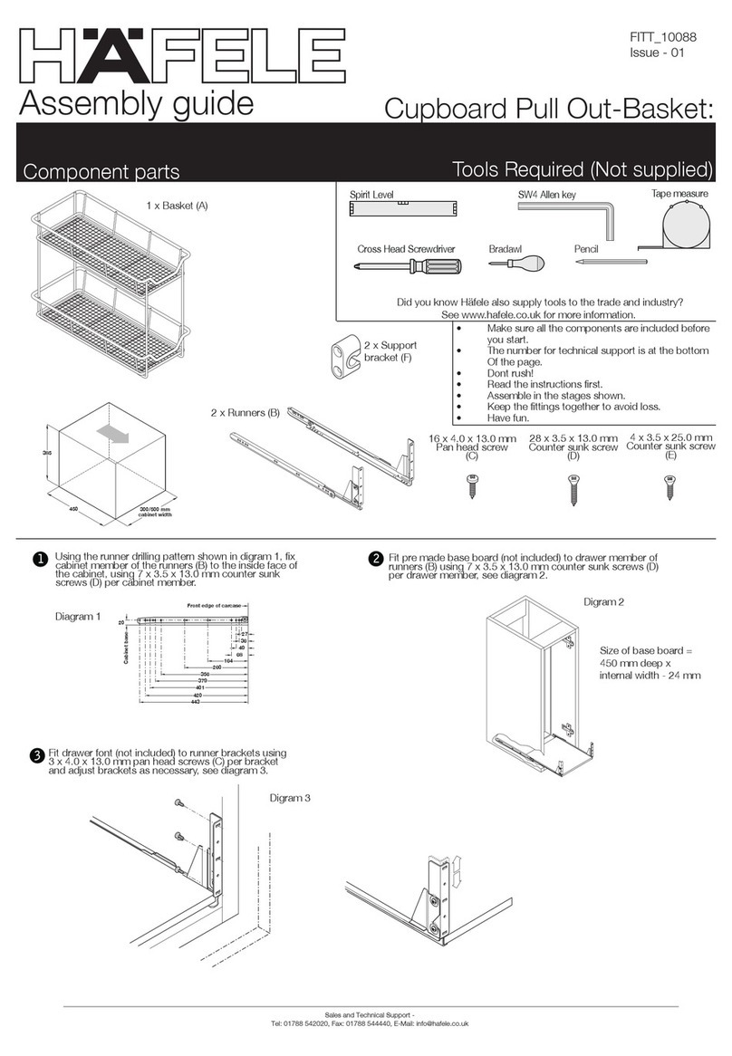
Hafele Cupboard Pull Out-Basket User manual

Hafele

Hafele Cupboard Pull Out-Basket User manual

Hafele Bettlift 271.91.114/115 User manual

Hafele

Hafele Bettlift 271.91.114/115 User manual

Hafele 633.50.202 User manual

Hafele

Hafele 633.50.202 User manual

Hafele Opla' Folding 78.1700.25 F User manual

Hafele

Hafele Opla' Folding 78.1700.25 F User manual

Hafele 502.00.407 User manual

Hafele

Hafele 502.00.407 User manual

Hafele Finetta Flatfront S20 US FB User manual

Hafele

Hafele Finetta Flatfront S20 US FB User manual

Hafele OPLA' TOP 1-901-002 User manual

Hafele

Hafele OPLA' TOP 1-901-002 User manual

Hafele Bettlift Foldaway Bed Fittings 271.95.203 Instruction sheet

Hafele

Hafele Bettlift Foldaway Bed Fittings 271.95.203 Instruction sheet

Hafele Duoletto 271.89.000 User manual

Hafele

Hafele Duoletto 271.89.000 User manual

Hafele A7F User manual

Hafele

Hafele A7F User manual

Hafele 271.92.132 User manual

Hafele

Hafele 271.92.132 User manual

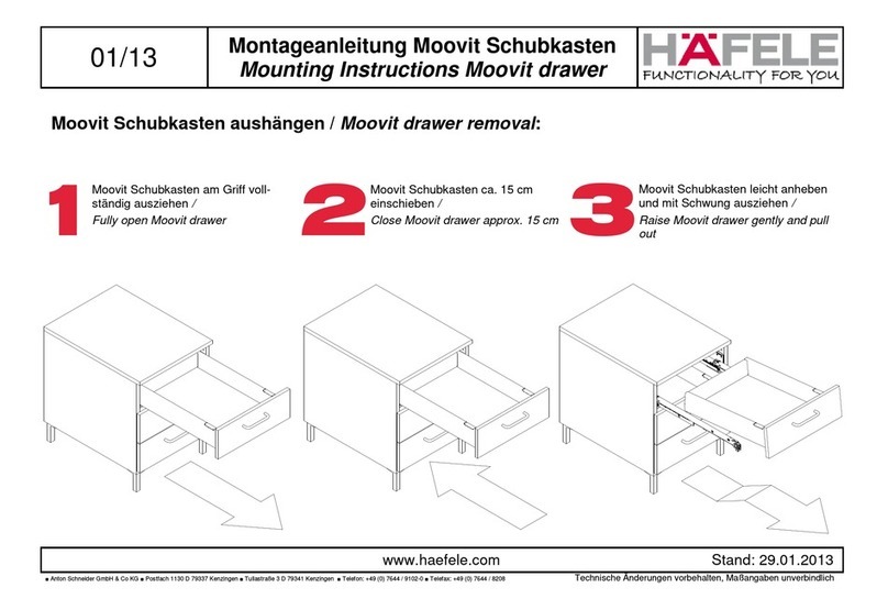
Hafele Moovit drawer User manual

Hafele

Hafele Moovit drawer User manual

Hafele MagicCorner Clever Storage User manual

Hafele

Hafele MagicCorner Clever Storage User manual

Popular Indoor Furnishing manuals by other brands

CHIEF PAC-150 installation instructions

CHIEF

CHIEF PAC-150 installation instructions

BOPITA BELLE 430055.11 Assembly instruction

BOPITA

BOPITA BELLE 430055.11 Assembly instruction

Safavieh Furniture Friar DCH1401 manual

Safavieh Furniture

Safavieh Furniture Friar DCH1401 manual

modway EEI-3052 quick start guide

modway

modway EEI-3052 quick start guide

Pyramat Sound Rocker S 2000 owner's manual

Pyramat

Pyramat Sound Rocker S 2000 owner's manual

HULALA HOME HZSTVS0249 manual

HULALA HOME

HULALA HOME HZSTVS0249 manual

Seaside Casual Adirondack 017 Assembly instructions

Seaside Casual

Seaside Casual Adirondack 017 Assembly instructions

Sauder Lateral File Boulevard Cafe 427345 manual

Sauder

Sauder Lateral File Boulevard Cafe 427345 manual

EDN Liverpool manual

EDN

EDN Liverpool manual

Homelegance 1032BR-3 Assembly instruction

Homelegance

Homelegance 1032BR-3 Assembly instruction

Universal Furniture Universal EXPLORE HOME 847-755 instruction sheet

Universal Furniture

Universal Furniture Universal EXPLORE HOME 847-755 instruction sheet

OSP Home Furnishings MET4224 manual

OSP Home Furnishings

OSP Home Furnishings MET4224 manual

OfficeSource PL102 Assembly instructions

OfficeSource

OfficeSource PL102 Assembly instructions

Living Spaces Sortino 288032 Assembly instructions

Living Spaces

Living Spaces Sortino 288032 Assembly instructions

Sonoma PRESTON 81SNRTB02 Assembly instructions

Sonoma

Sonoma PRESTON 81SNRTB02 Assembly instructions

Safavieh Leyla SFV4720 quick start guide

Safavieh

Safavieh Leyla SFV4720 quick start guide

MID.YOU FRTD021 Assembly instructions

MID.YOU

MID.YOU FRTD021 Assembly instructions

Furniture of America CM7187N Assembly instructions

Furniture of America

Furniture of America CM7187N Assembly instructions

manuals.online logo
manuals.online logoBrands
  • About & Mission
  • Contact us
  • Privacy Policy
  • Terms and Conditions

Copyright 2025 Manuals.Online. All Rights Reserved.