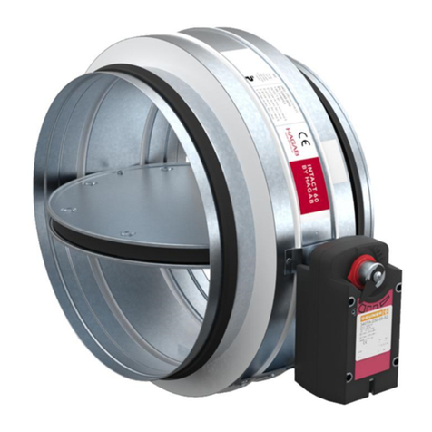
HAG INTACT Installation and operating instructions

1
HAGAB – INSTALLATION, OPERATION AND MAINTENANCE
HOLE DIMENSIONS
D+50mm, i.e. the nominal fitting dimension of the
damper + 50 mm.
Other sealing methods may result in other hole dimensions.
DAMPER INSTALLATION
1. Installation sleeve
For installation in light stud walls, use an installation sleeve
or a similar approved sealant and caulking for the duct
lead-through.
The sleeve supplied by HAGAB is in two parts and is
adapted to fit in the hole for each damper size.
2. Fix the duct
Fix the duct to be installed
through the structural element
against the damper fitting with
plate screws.
Note the installation direction of
the damper.
3. Centering in the hole
Place the damper casing flush against the structural
element, centre it in the hole and fix laterally with
the damper and duct system suspension devices.
INTACT
Fire/Fire gas damper
D + 50 mm
According to EN1366-2
Circular damper to prevent the spread of fire and fire gas.
For installation against or separated from fire-rated structural
elements. The damper has a fire resistance rating of EI 60
(ve i o)S, EI 60 (ho i o)S. See EC certificate 0402-CPR-
SC1119-11. Tested according to a harmonised product
standard, which means that the product is CE marked.
RISE certification also provides increased safety and quality.
Drawing name:

2
HAGAB – INSTALLATION, OPERATION AND MAINTENANCE
4. Opposite side of the duct
Install the duct on the other side of the structural element
and fix it to the damper fitting with plate screws.
5. Suspension devices
Suspension devices for the damper must match the fire
resistance rating of the structural element. See for example
the Svensk Ventilation/HVAC Technical Association’s manual
“Practical solutions for fire protection and ventilation”.
6. Lead-though/Sealant
The space between the installation sleeve and connecting
duct can be fitted with fireproof insulation made of mineral
wool or an equivalent sealant.
DAMPER INSTALLATION – CONCRETE JOISTS
1. Installation
Install the ventilation duct mounted to the damper
according to the same principle as for a vertical structural
element but without an installation sleeve.
Centre the damper and fix to the top of the joists with
the supplied L brackets. Refinish the space between the
ventilation duct and the joists with concrete mortar or a
certified fire protection compound.
INTACT
Fire/Fire gas damper
Refinishing
The damper is
installed on the
top of the joists
Drawing name:

3
HAGAB – INSTALLATION, OPERATION AND MAINTENANCE
DAMPER INSTALLATION – SEPARATED WALLS
1. Installation sleeve
For installation in light stud walls, use an installation
sleeve or a similar approved seal and caulking for the
duct lead-through.
The sleeve supplied by HAGAB is in two parts and is
adapted to fit in the hole for each damper size.
Fit the parts together from each direction against the wall/
structural element and screw them together. Maximum
thickness of the structural element is 180 mm.
2. Install the duct
Centre the duct against the installation sleeve. Suspension
devices for the duct must match the fire resistance rating of
the structural element.
See for example the Svensk Ventilation/HVAC Technical
Association’s manual “Practical solutions for fire protection
and ventilation”.
Fit the space between the installation sleeve and
connecting duct with fireproof insulation made of
mineral wool or an equivalent sealant.
INTACT
Fire/Fire gas damper
D + 50 mm
Drawing name:

4
HAGAB – INSTALLATION, OPERATION AND MAINTENANCE
3. Installation
Install the damper in the ventilation duct. The shaft of the
damper can be installed in any position. Fix with plate
screws. Suspension devices for INTACT must match the fire
resistance rating of the structural element. See for example
the Svensk Ventilation/HVAC Technical Association’s manual
“Practical solutions for fire protection and ventilation”.
4. No connection in the duct system
If the fire/fire gas damper is not connected to
the duct system, e.g. when installing as a closing device or
transfer air device, the damper must be fitted with contact
grilles on the non-connected side. The minimum permissi-
ble distance between the damper
blade in the open position and the grille is 50 mm.
6. Insulation
Insulate the duct to an approved method according
to the insulation supplier’s instructions.
Note that the insulation must cover the whole
INTACT damper.
5.
6.
D + 50 mm
ev. 4.
3.
5. Thermal sensor
Install the thermal sensor with the sensing unit in the air flow
without hindering damper blade movement.
Drawing name:

DETECTION
To protect against the spread of both fire and fire gas, the
damper must be controlled by a smoke detector mounted in
the ventilation duct near the damper or in another suitable
location and be equipped as specified below.
To protect against the spread of fire alone, the damper must
be controlled by a smoke and/or heat detector mounted in
the ventilation duct near the damper or in another suitable
location.
The heat detector must close the damper at a temperature
of no more than +72 degrees in the duct.
CONTROL
The fire gas damper must be function tested at least once
every 48 hours. The function test means that the dampers
must close and open at intervals as above.
The function test must be performed automatically and can
be controlled by e.g. a control and monitoring system.
MONITORING
At the function test interval, the damper’s closing function
is checked automatically. If any damper does not close, a
malfunction should be indicated immediately.
OPERATING AND MAINTENANCE INSTRUC-
TIONS
Periodic inspection once per year.
INTERNAL CONTROL VIA INSPECTION COVER
OR CLEANOUT DOOR IN CONNECTING DUCT
– Check by triggering the smoke detector so the
damper closes.
– Check that the damper blade closes and opens freely by
switching off power to the actuator. If the junction box
KBHA-1 is installed, press the “DAMPER TEST” button.
Keep the button pressed to interrupt the voltage to the
actuator. Alternatively, the voltage can be interrupted by
pressing the “Test” button on the damper’s thermal sensor.
– Check the fitting of the sealing strip on the damper blade.
– Check the cleaning requirements in conjunction with the
ventilation system function test.
EXTERNAL CONTROL
– Check that the damper frame has not been
subjected to mechanical damage.
– Check that the seal in the structural element has
not been damaged.
– Check the fitting of the actuator on the shaft and frame.
– Check that the actuator cabling is not damaged.
– Check that the damper is clean. If necessary, wipe with
a slightly dampened cloth.
CLEANING
– When cleaning the inside of the damper, always choose
a gentle cleaning method such as a nylon brush and/or
compressed air.
SPARE PARTS LIST
Actuator brand Gruner or Belimo, see rating plate on
the actuator.
HAGAB – INSTALLATION, OPERATION AND MAINTENANCE
Flodin Fernström | 01 2019
INTACT
Fire/Fire gas damper
Hagab Box 135, 56202 Taberg
|
Visit Industrivägen 5, 56241 Taberg
|
Phone 036-363090
|
Fax 036-363099
|
www.hagab.com
|
Sales Office Jönköping Phone 036-363090
|
Stockholm Phone 08-6899010
Drawing name:
Other manuals for INTACT
1
Other HAG Fire And Smoke Damper manuals
Popular Fire And Smoke Damper manuals by other brands

Schako
Schako ERK-MB Series Technical documentation

SMAY
SMAY WKZ-O installation manual

FläktGroup
FläktGroup ETPR-E-1 Instructions for installation, operation and maintenance

Tamco
Tamco AIR-IQ2 Installation guidelines

Komfovent
Komfovent LMV-D3-MF-F installation instructions

Greenheck
Greenheck CRD-300WT Installation, operation and maintenance manual