Appendix D:
KE24 Operating Tips
In the event that you are experiencing difficulty in using your KE24,
please check the following items before calling us:
•When connecting the KE24 to a PC and keyboard, make sure they
are plugged into the proper ports. The connector marked “To PC”
on the KE24 must be connected to the PC keyboard input. Attach
your computer keyboard to the KE24 connector marked “KBD.” The
KE24 will not function properly if these connections are reversed.
•Check your KE24 configuration. Be sure to select the type of
computer that you are using (XT or AT compatible). Check your I/O
configuration for the number of columns and rows, etc. Review your
matrix or discrete input table for the desired responses.
•If you are having trouble getting your PC keyboard to work with the
KE24, make sure that the keyboard itself is configured for the type
of computer you have specified in the configuration (XT or AT
compatible).
•The maximum recommended cable length from your computer to the
KE24 is 10 feet. This distance is also the maximum length that you
should use on connections from the switches or keypads in your
applications to the KE24 I/O header.
•If your KE24 will not communicate with the KE24Load program,
check the COM port selection. Also be sure to power up the KE24
with the programming jumper in place. Refer to page 12 for more
information on programming the KE24 unit.
•If you cannot get the KE24 to respond to your configuration, make
sure that you have removed the programming jumper and powered
the unit back up without the jumper in place.
If you have any questions that are not answered in this manual,
please give us a call. We have customer service available from
8:00 am to 5:00 p.m. (Eastern) Monday through Friday.
(540) 465-4677
28
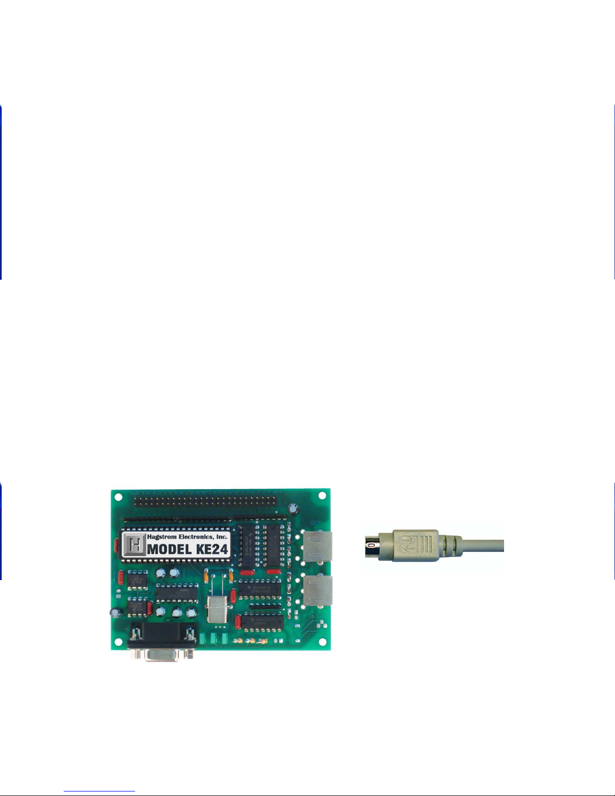
Introduction to the KE24
The KE24 Keyboard Encoder is a product designed to interface
keypads, switches, or RS-232 to your computer’s keyboard input.
Additionally, the RS-232 serial communication port may be used
in a variety of other ways to create the type of interface that you
require.
The KE24 is user programmable. This feature allows you to
configure the I/O and select the operating modes for the unit.
Nonvolatile memory stores your configuration information.
The KE24 I/O:
The 52 pin header in the KE24 provides 24 I/O signals that can
be programmed to scan a matrix or discrete inputs. Any of the 24
I/O pins can be programmed as a Row or Column in a matrix
application, or as an individual input. A matrix size from 1x1 to
12x12 can be scanned. I/O pins not assigned as Rows or Columns
in a matrix application may be used as discrete inputs. Input from
the I/O header may be directed to the PC keyboard input, or to
the KE24 RS-232 port.
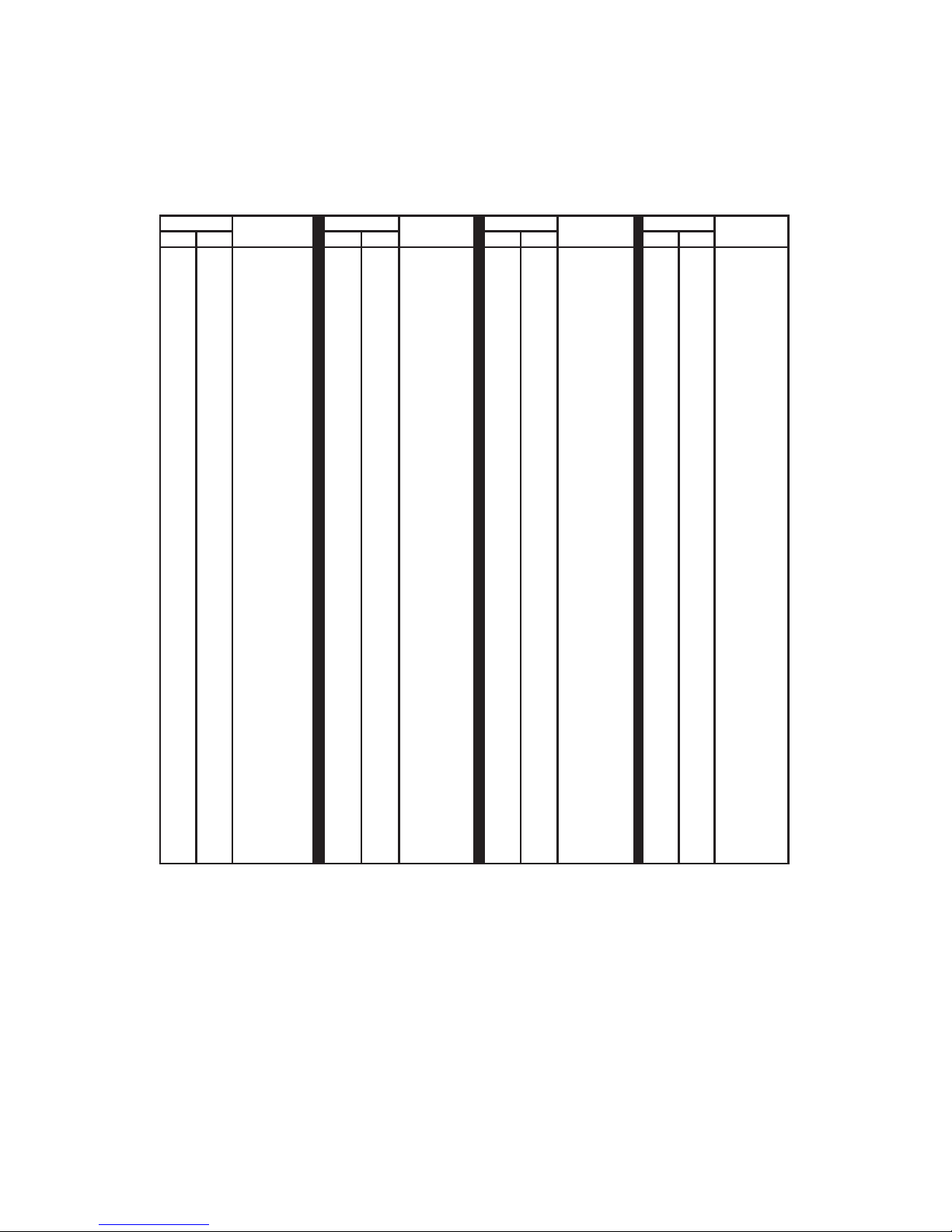
Modes of KE24 operation:
These modes may be used individually or combined with other
modes of operation.
3
Input Output
RS-232 PC Keyboard Input
Keypads or Switches PC Keyboard Input
Keypads or Switches RS-232 Port
PC Keyboard PC Keyboard Input
PC Keyboard RS-232 Port