Step4
The KEUSB24 has the capability to assign Shift, Ctrl, and Alt
functions along with a keystroke. For this sample setup, one of
the keys is defined as theCtrl+Alt+Del sequence. The keystrokes
emulated by this combination have the same effect as holding
the control and alt keys, then pressing the delete key on a PC
keyboard. To create this input, check theCtrl and Alt boxes on
the lower left corner of the keyboard diagram, then click onthe
Del button (shown below).
Any position inthe KEUSB24 matrix can be modified by one or a
combination oftwo of the Shift, Alt, or Ctrl keys using the method
described above. Use the Shift function to generate upper case
characters, or shifted characters (!, @, etc.) inthe application. To
remove one ofthese special functions, uncheck the appropriate
box and click on the desired key.
138
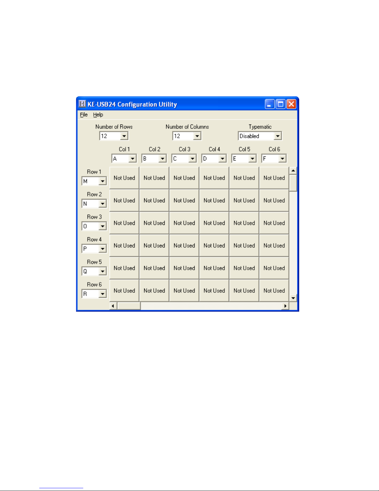
Open:Recall a previously saved configuration file by either
clicking on “Open” with the mouse or by pressing Ctrl+O onthe
keyboard. Locate and select the name ofthe configuration file
on the PC that is to be opened.
Save:Once a configuration setup has been created onthe
program screen, it isrecommended that it be saved onthe PC’s
hard disk. Click on “Save” with the mouse or press Ctrl+S onthe
keyboard, then choose a location to save the file.
Read fromKEUSB24 (1): This option will read the current
configuration inthe KEUSB24 and display it on the screen. Click
on “Read from KEUSB24” with the mouse or press Ctrl+R onthe
keyboard to perform this operation.
Write to KEUSB24 (1): This option will write the current
configuration displayed onthe screen to the KEUSB24. The
KEUSB24 can be programmed and re-programmed as many
times as necessary.Click on “Write to KEUSB24” with the mouse
or press Ctrl+W onthe keyboard to perform this operation. After
the KEUSB24 has been loaded with the new configuration, it will
scan according to this new setup.
Read fromKEUSB24 (2): This option will read the current
configuration from a unit configured as Device ID 2.
Write to KEUSB24 (2): This option will write the current
configuration from a unit configured as Device ID 2.
Exit: This option exits and closes the KEUSB24.EXE program.
*Note: Make sure that the KEUSB24 is connected to the PC
before performing either the “Read to KEUSB24” or “Write to
KEUSB24” operations. If the KEUSB24 is not present, a “The
KEUSB24 was not Found” error will be displayed on the computer
screen.