Haier 1U160S2SP1FB User manual

SPLIT SYSTEM AIR CONDITIONER
INSTALLATION MANUAL
1U160S2SP1FB
No. 0150544326
yThis product must only be installed or serviced by qualied personnel.
Please read this manual carefully before installation.This appliance is lled with R32.
Keep this manual for future reference.
Original instructions
Contents
Denitions.............................................. 6
Safety considerations ............................ 6
Before installation.................................. 8
Selecting installation site ....................... 9
Precautions on installation................... 11
Refrigerant pipe size and allowable
pipe length........................................... 12
Refrigerant piping ................................ 15
Leak test andvacuum drying................ 17
Charging refrigerant............................. 18
Electrical wiring work........................... 19
Test operation...................................... 21
Move and scrap the air conditioning.... 25
English


3
Português
Haier Industrial Park,Qianwangang Road,Eco-Tech Development Zone,Qingdao 266555,Shandong,P.R.C.
EUROPEAN REGULATIONS
CONFORMITY FOR THE MODELS
IMPORTANT INFORMATION REGA-
RDING THE REFRIGERANT USED
CE
All the products are in conformity with the following
European provision:
- Low voltage Directive
- Electomagnetic Compatibility
ROHS
The products are fullled with the requirements in
the directive 2011/65/EU of the European parliament
and of council on the Restriction of the use of Certain
Hazardous Substances in Electrical and Electronic
Equipment(EU RoHS Directive)
WEEE
In accordance with the directive 2012/19/EU of the
European parliament,herewith we inform the consumer
about the dis- posal requirements of the electrical and
electronic products.
DISPOSAL REQUIREMENTS:
Your air conditioning product is marked
with this symbol.This means that electrical
and electronic products shall not be mixed
with unsorted household waste.Do not
try to dismantle the system yourself:the
dismantling of the air conditioning system,treatment of
the refrigerant,of oil and of other part must be done by
a qualied installer in accordance with relevant local
and national legislation.Air conditioners must be treated
at a specialized treatment facility for reuse, recycling
and recovery.By ensuring this product is disposed of
correctly,you will help to prevent potential negative
cons- equences for the environment and human health.
Please contact the installer or local authority for more
information.Battery must be removed from the remote
controller and dis- posed of separately in accordance
with relevant local and national legislation.
This product contains uorinated greenhouse gases
covered by the Kyoto Protocol.Do not vent into the
atmosphere.
Refrigerant type:R32
GWP:675
GWP=global warming potential
Please ll in with indelible ink,
y1 the factory refrigerant charge of the product
y2 the additional refrigerant amount charged in the
eld and
y1+2 the total refrigerant charge
on the refrigerant charge label supplied with the product.
The lled out label must be adhered in the proximity of
the product charging port(e.g.onto the inside of the2 stop
value cover).
A contains uorinated greenhouse gases covered by the
Kyoto Protocol
B factory refrigerant charge of the product:see unit name
plate
C additional refrigerant amount charged in the eld
D total refrigerant charge
E outdoor unit
F refrigerant cylinder and manifold for charging
Contains uorinated greenhouse gases
covered by the Kyoto Protocol

4
Read the precautions in
this manual carefully before
operating the unit.
This appliance is lled with R32.
Read the operator's manual Service indicator, read technical
manual
After reading this handbook, hand it over to those who will be using the unit.
The user of the unit should keep this mamual at hand and make it available to those who will be performing repairs or
relocating the unit. Also, make it available to the new user when the user changes hands.
WARNING
Ask your dealer or qualied personnel to carry out installation work.Do not attempt to install the air conditioner
yourself. Improper Installation may result in water leakage, electric shocks, re or explosion. All the cables shall
have got the European authentication certicate. During installation, when the connecting cables break off, it must
be assured that the grouding wire is the last one to be broken off.If refrigerant gas leaks during installation, ventilate
the area immediately.oxic gas may be produced.if the refrigerant comes into contact with re,and explosion may be
happen.
Make sure ground connection is correct and reliable.Do not earth the unit to a utility pipe, lightning conductor or
telephone earth lead. Imperfect earthing may result in electric shocks.
The breaker of the air conditioner should be all-pole switch and explosion-proof. The distance between its two
contacts should not be no less than 3mm. Such means for disconnection must be incorporated in the wiring.
The air conditioning sockets should be placed 1m above from the air conditioner, nor under the air conditioner. Be
sure not to use open ame, high static electrical or high temperature equipments etc.nearby the air conditioner.
Do not use means to accelerate the defrosting process or to clean, other than those recommended by the
manufacturer.
The appliance must be stored in a room without continuously operating ignition sources, the radius of the storage area
should be no less than 2.5 m (for example:open ames, an operating gas appliance or an operating electric heater).
Do not pierce or burn.
Be aware that refrigerants may not contain an odour.
The appliance must be installed, operated and stored in a room with a oor area larger than the Minimum Room Area
specied in the table on the following pages,The room should be well ventilated.
Comply with national gas regulations.
This appliance can be used by children aged 8 years and above and persons with reduced physical, sensory or
mental capabilities or lack of experience and knowledge if they have been given superivision or instruction concering
use of the appliance in a safe way and understand the hazards involved. Children shall not play with the appliance.
Cleaning and user maintenance shall not be made by children without supervision.
The air conditioner can not be discarded or scrapped Randomly If you need please contact customer service
personnel of Haier to scrap in order to obtain the correct disposal methods.
Reusable mechanical connectors and ared joints are not allowed indoor.
CAUTION
Do not install the air conditioner at any place where there is danger of ammable gas leakage.In the event of a gas
leakage, build-up of gas near the air conditioner may cause a re to break out.
Tighten the are nut according to the specied method such as with a torque wrench.If the are nut is too tight, it may
crack after prolonged use, causing refrigerant leakage.
Take adequate steps to prevent the outdoor unit being used as a shelter by small animals.Small animals.making
contact with electrical parts can cause malfunctions, smoke or re.
Please instruct the customer to keep the area around the unit clean
The temperature of refrigerant circuit will be high, please keep the inter-unit wire away from copper pipes that not
thermally insulated.
Only qualied personnel can handle, ll, purge and dispose of the refrigerant.

5
Português
WARNING
If the supply cord is damaged, it must be replaced by the manufacturer, its service agent or similarly qualied persons
in order to avoid a hazard.
This appliance is not intended for use by persons (including children) with reduced physical, sensory or mental
capabilities, or lack of experience and knowledge, unless they have been given supervision or instruction concerning
use of the appliance by a person responsible for their safety.
Children should be supervised to ensure that they do not play with the appliance.
This appliance can be used by children aged from 8 years and above and persons with reduced physical, sensory or
mental capabilities or lack of experience and knowledge if they have been given supervision or instruction concerning
use of the appliance in a safe way and understand the hazards involved. Children shall not play with the appliance.
Cleaning and user maintenance shall not be made by children without supervision.
The appliances are not intended to be operated by means of an external timer or separate remote-control system.
Keep the appliance and its cord out of reach of children less than 8 years.
This appliance is intended to be used by expert or trained users in shops, in light industry and on farms, or for
commercial use by lay persons.
Disconnect the appliance from its power source during maintenance service and when replacing parts.
1) Means for disconnection, such as circuit breaker, which can provide full disconnection in all poles, must be
incorporated in the xed wiring in accordance with the wiring rules.
It is necessary to allow disconnection of the appliance from the supply after installation. The disconnection may be
achieved by incorporating a switch in the xed wiring in accordance with the wiring rules.
The method of connection of the appliance to the electrical supply and interconnection of separate components, and
the wiring diagram with a clear indication of the connections and wiring to external control devices and supply cord are
detailed in below parts.
2) The appliance shall be installed in accordance with national wiring regulations. Wiring must be done by a qualied
electrician. All the wiring must comply with the local electrical codes.
3) The cord of the H05RN-F type or the electrically equivalent type must be used for power connection and
interconnection between outdoor unit and indoor unit. The size of the cord is detailed in below parts.
4) Details of type and rating of fuses, or rating of circuit breakers / ELB is detailed in below parts.
5) The information of dimensions of the space necessary for correct installation of the appliance including the
minimum permissible distances to adjacent structures is detailed in below parts.

6
1. Denitions
1.1. Meaning of warnings and symbols
Warnings in this manual are classied according to their
severity and probability of occurrence.
DANGER
Indicates an imminently hazardous situation which,
if not avoided, will result in death or serious injury.
WARNING
Indicates a potentially hazardous situation which, if
not avoided, could result in death or serious injury.
CAUTION
Indicates a potentially hazardous situation which, if
not avoided, may result in minor or moderate injury. It
may also be used to alert against unsafe practices.
NOTICE
Indicates situations that may result in equipment
or property-damage accidents only.
INFORMATION
This symbol identies useful tiops or additional
information.
Some types of danger are represented by special symbols:
Electric current.
Danger of burning and scalding.
1.2. Meaning of used terms
Installation manual:
Instruction manual specied for a certain product or
application, explaining how to install, congure and
maintain it.
Operation manual:
Instruction manual specied for a certain product or
application, explaining how to operate it.
Maintenance instructions:
Instruction manual specied for a certain product or
application, which explains ( if relevant ) how to install,
congute, operate and/or maintain the product or
application.
Dealer:
Sales distributor for products as per the subject of this
manual.
Installer
Technical skilled person who is qualied to install
products as per the subject of this manual.
User:
Person who is owner of the product and/or operates the
product.
Service company:
Qualied company which can perform or coordinate the
required serice to the unit.
Applicable legislation:
All international, European, national and local directives,
laws, regulations and/or codes which are relevant and
applicable for a certain product or domain.
Accessories:
Equipment which is delivered with the unit and which
needs to be installed according to instructions in the
documentation.
Optional equipment:
Equipment which can ooptionally be combined to the
products as per the subject of this manual.
Field supply:
Equipment which needs to be installed according to
instructions in this manual, but which are not supplied by
Haier.
2. Safety considerations
The precautions here, all cover very impertant topics, so
be sure to follow them catefully.
All activities described in this manual shall be carried out
by an installer.
Be sure to wear adequate personal protection equipment
( Protection gloves, safety glasses......) when performing
installation, maintenance or service to the unit.
If not sure of installation procedures or operation of the unit,
always contact your local dealer for advice and information.
Improper installation or attachment of equipment or
accessories could result in electric shock, short-circuit,
leaks, re or other damage to the equipment. Be sure
only to use accessories, optional equipment and spare
parts made by which are specially designed for use with
the products as of subject in this manual and have them
installed by an installer.
DANGER: ELECTRICAL SHOCK
Switch off all power supply before removing the switch
box service panel or before making any connections or
touching electrical parts.
To avoid electric shock, be sure to disconnect the power
supply 2 minute or more before servicing the electrical
parts. Even after 2 minute, always measure the voltage
at the terminals of main circuit capacitors or electrical
parts. Even after 2 minute, always measure the votage
at the terminals of main circuit capacitors or electrical
parts, and before touching, be sure that those voltages
are 50V DC or less.
When service panels are removed, live parts can easily
be touched by accident, Never leave the unit unattended
during installation or servicing when the service panel is
removed.

7
Português
DANGER: DO NOT TOUCH PIPING
ANDINTERNAL PARTS
Do not touch the refrigerant piping, water piping or
internal parts during and immediately after operation.
The piping and internal parts may be hot or cold
depending on the working condition of the unit.
Your hand may suffer burns or frostbite if you touch
the piping or internal parts. To avoid injury, give the
piping and internal parts time to return to normal
temperature or, if you must touch them, be sure to
wear protective gloves.
Warning:
Ask your dealer or qualied personnel to carry out
installation work. Do not install the machine by
yourself. Improper installation may result in water
leakage, electric shocks or re.
Perform installation work in accordance with this
installation manual.
Improper installation may lead to water leakage,
electric shocks or re.
The equipment is not intended for use in a potentially
explosive atmosphere.
For 1UH series units only.
For year round cooling applications with low indoor
humidity conditions, such as Electronic Data
Processing rooms, contacet yout dealer or see the
engineering databook or the service manual.
Consult your local dealer regarding what to do in case
of refrigerant leakage. When the unit is to be installed in
a small room, it is necessary to take proper measures
so that the amount of any leaked refrigerant does not
exceed the concentration limit in the event of a leakage.
Otherwise, this may lead to an accident due to oxygen
depletion.
Be sure to use only the specied accessories and
parts for installation work.
Failure to use the specied parts may result in water
leakage, electric shocks, re, or the unit falling.
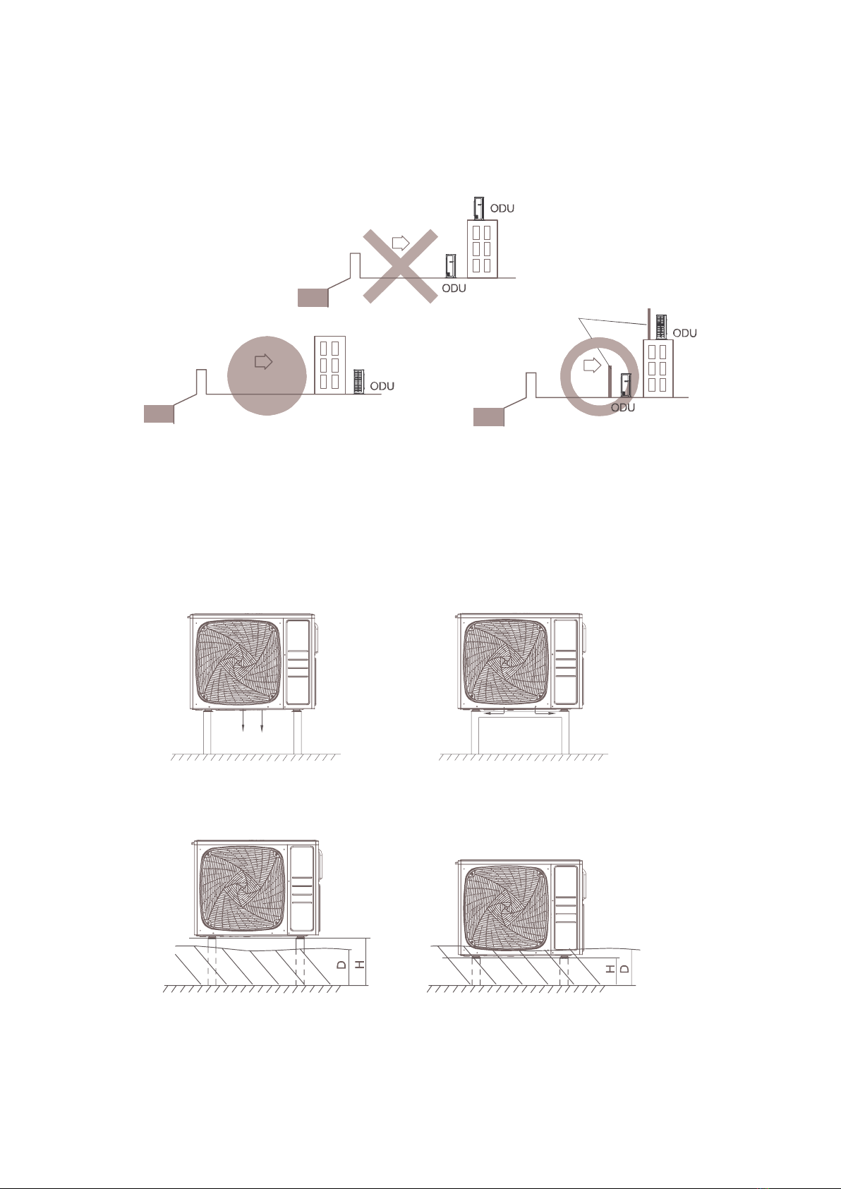
Install the unit on a foundation that can withstand its
weight.
Insufcient strength may result in the fall of equipment
and causing injury.
Carry out the specied installation work in consideration
of strong winds, typhoons, or earthquakes.
Improper installation work may result in accidents due
to fall of equipment.
Make sure that all electrical work is carried out by
qualied personnel according to the applicable legislation
and this installation manual, using a separate circuit.
Insufcient capacity of the power supply circuit or
improper electrical capacity of the power supply
circuit or improper electrical construction may lead to
electric shocks or re.
Make sure that all wiring is secure, using the specied
wires and ensuring that external forces do not act on
the terminal connections or wires.
Incomplete connection or xing may cause a re.
When wiring between the indoor and outdoor units,
and wiring the power supply, form the wires so that
the fronstside panel can be securely fastened.
If the frontside panel is not in place, overheating of
the terminals, electric shocks or a re may be caused.
If refrigerant gas leaks during installation work,
ventilate the area immediately.
Toxic gas may be produced if refrigerant gas comes
into contactwith re.
After completing the installation work, check to make
sure that there is no leakage of refrigerant gas.
Toxic gas may be produced if refrigerant gas leaks
into the room and comes into contact with a source of
re, such as a fan heater, stove or cooker.
When planning to relocate former installed units, you
must rst recover the refrigerant after the pump down
operation.
Never directly touch any accidental leaking refrigerant.
This could result in severe wounds caused by frostbite.
Be sure to install an earth leakage circuit breaker in
accordance with applicable legislation. Failure to do so
may cause electrical shock and re.
Caution:
Earth the unit.
Earthing resistance should be according to applicable
legislation.
Do not connect the earth wire to gas or water pipes,
lightning conductor or telephone earth wire.
Incomplete earthing may cause electric shocks.
Gas pipe.
Lgnition or explosion may occur if the gas leaks. Water
pipe.
Hard vinyl tubes are not effective earths. Lightning
conductor or telephone earth wire. Electric potential
may rise abnormally if struck by a lightning bolt.
Install drain piping according to this installation manual
to ensure good drainage, and insulate the pipe to
prevent condensation.
Improper drain piping may cause water leakage, and
make the fumitures get wet.
Install the indoor and outdoor units, power wire and
connecting wire at least 1 meter away from televisions
or radios to prevent image interference or noise.
(Depending on the radio waves, a distance of 1 meter
may not be sufcient to eliminate the noise.)
Do not rinse the outdoor unit, This may cause electric
shocks or re.
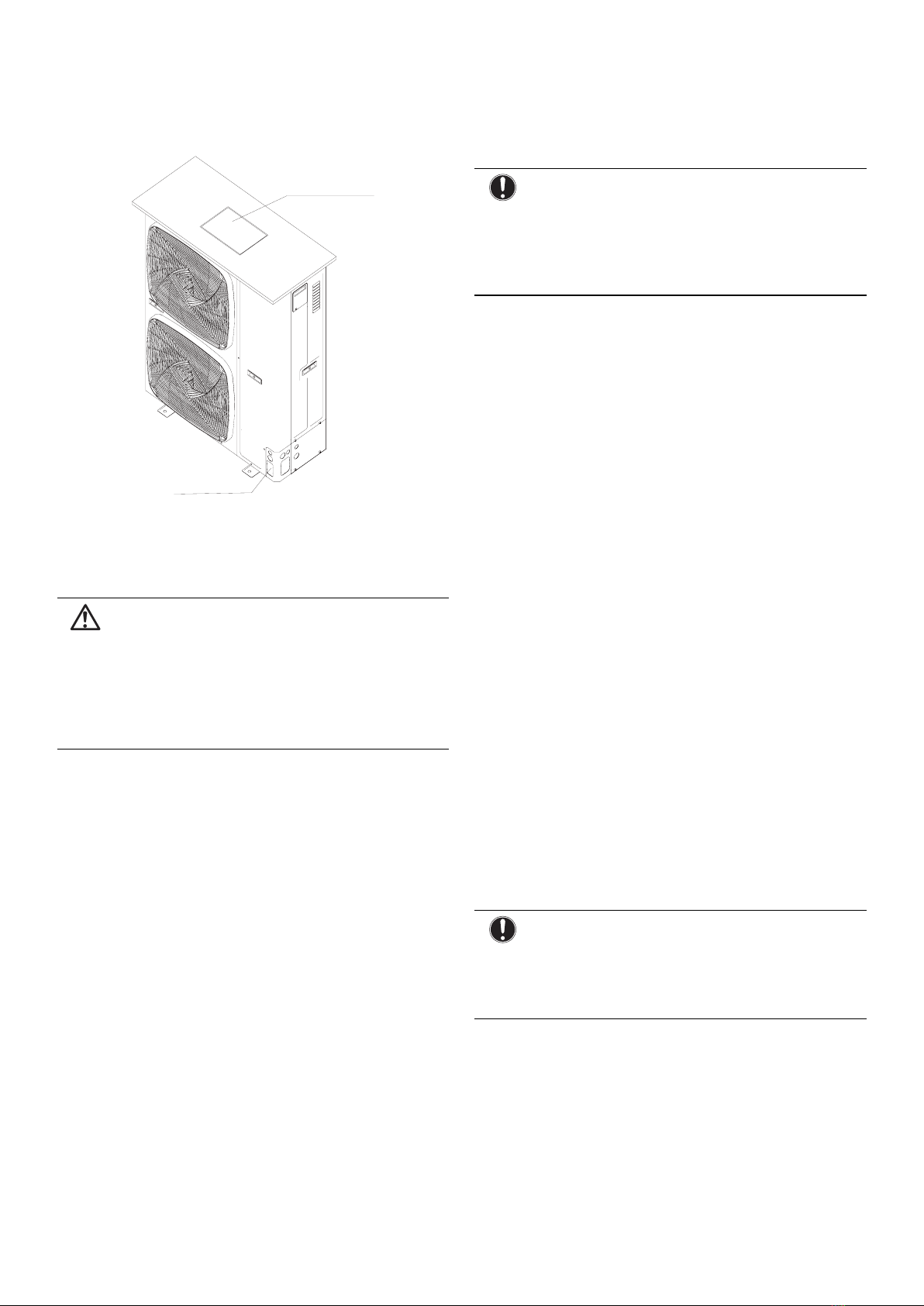
Do not install the unit in places such as the following:
Where there is mist of mineral oil, oil spray or vapour
for example a kitchen.
Plastic parts may deteriorate, and cause them to fall
out or water to leak.

8
Where corrosive gas, such as sulphurous acid gas, is
produced.
Corrosion of copper pipes or soldered parts may
cause the refrigerant to leak.
Where there is machinery which emits electromagnetic
waves.
Electromagnetic waves may disturb the control
system, andcause malfunction of the equipment.
Where ammable gases may leak, where carbon
ber or ignitable dust is suspended in the air or where
volatile ammables, such as thinner or gasoline, are
handled. SUch gases may cause a re.
Where the air contains high levels of salt such as that
near the ocean.
Where voltage uctuates a lot, such as in factories.
In vehicles or vessels.
Where acidic or alkaline vapour is present.
Do not allow a child to mount on the outdoor unit
or avoid placing any object on the unit. Falling or
tumbling may result in injury.
The unit may stop for several minutes during
normal operation for "defrosting the unit", or when in
"thermostat stop" operation.
This appliance is intended to be used by expert or
trained users in shops, in light industry and on farms,
or for commercial use by lay persons.
Provide a logbook
In accordance with the relevant national and
international codes, it may be necessary to provide a
logbook with the equipment containing at least
- info on maintenance.
- repair work,
- results of tests,
- stand-by periods,
- etc...
In Europe, EN378 provides the necessary
guidance for this logbook.
3. Before installation
3.1. Scope of this manual
This manual describes the procedures for handling,
installing and connecting 1U160 unit.
3.2 Precautions
CAUTION
Since maximum working pressure is 4.3 MPa or 43.0
bar, pipes of larger wall thickness may be required.
Refer to paragraph "6.2. Selection of piping material"
on page 10.
NOTICE: Insulation resistance of the
compressor
If, after installation, refrigerant accumulates in the
compressor, the insulation resistance can drop, but if
it is at least 1 , then the machine will not break down.
Turn the power on and leave it on for six hours. Then,
check if the insulation resistance of the comressor
has risen or not.
The compressor will heat up and evaporate any
refrigerant in the compressor.
Check the following if the ground-fault circuit
interrupter is triggered:
Make sure that the interrupter is compatible with high
frequencies.
This unit has an inverter, so an interrupter capable
of handling high frequencies is needed to prevent
malfunction of the interrupter itself.
3.3. Precautions for R32
The refrigerant requires strict cautions for keeping the
system clean, dry and tight.
-Clean and dry
Foreign materials (including mineral oils or moisture)
should be prevented from getting mixed into the system.
-Tight
Read "9. Precautions on refrigerant piping" on page
10 carefully and follow these procedures correctly.
Since R32 is a mixed refrigerant, the required
additional refrigerant must be charged in its liquid
state.(If the refrigerant is in state of gas, its composition
changes and the system will not work properly).
The connected indoor units must be indoor units
designed exclusively for R32.
3.4. Installation
For installation of the indoor unit(s), refer to the indoor
unit installation manual.
Illustrations show 1U160S2SP1FB outdoor unit type.
This outdoor unit requires the pipe branching
kit(optional) when used as the outdoor unit for the
simultaneous operation system. Refer to catalogues
for details.
Never operate the unit with a damaged or
disconnected discharge thermistor and suction
thermistor, burning of the compressor may occur.
Be sure to conrm the model name and the serial no.
of the outer(front) plates when attaching/detaching
the plates to avoid mistakes.
When closing the service panels, take care that the
tigntening torque does not exceed 4.1 N.M.

9
Português
3.5 Accessories
Check if the following accessories are included with the unit:
See the gure below for the location of the accessories.
4. Selecting installation site
4.1. General
WARNING
Be sure to provide for adequate measures in order
to prevent that the outdoor unit be used as a shelter
bye small animals.
Small animals making contact with electrical parts can
cause malfunctions, smoke or re. Please instruct the
customer to keep the area around the unit clean.
Select an installation site where the following conditions
are satised and that meets with your customer's
approval.
- Places which are well-ventilated.
- Pllaces where the unit does not bother next-door
neighbours.
- Safe places which can withstand the unit's weight and
vibration and where the unit can be installed level.
- Places where there is no possibility of ammable
gas or product leak.
- The equipment is not intended for use in a potentially
explosive atmosphere.
- Places where servicing space can be well ensured.
- Places where the indoor and outdoor units's piping
and wiring lengths come within the allowable ranges.
- Places where water leaking from the unit cannot
cause damage to the location (e.g. in case of a
blocked drain pipe)
- Places where the rain can be avoided as much as possible.
- Do not install the unit in places often used as work
place. In case of construction works (d.g.grinding works )
where a lot of dust is created, the unit must be covered.
- Do not place any objects or equipment on top of the
unit (top plate).
installation
manual
rubber
base foot
- Do not climb, sit or stand on top of the unit.
- Be sure that sufcient precautions are taken, in
accordance with applicable legislation, in case of
refrigerant leakage.
NOTICE
This is a class A product. In a domestic environment
this product may cause radio interference in which
case the user may be required to take adequate
measures.
When installing the unit in a place exposed to strong
wind, pay special attention to the following.
Strong winds of 5 m/sec or more blowing against the
outdoor unit's air outlet causes short circuit (suction
of discharge air), and this may have the following
consequences:
- Deterioration of the operational capacity.
- Frequent frost acceleration in heating operation.
- Disruption of operation due to rise of high pressure.
- When a strong wind blows continuously on the face of
the unit, the fan can start rotating very fast until it breaks.
Refer to the gures for installation of this unit in a
place where the wind direction can be foreseen.
Repare a water drainage channel around the
foundation, to drain waste water from around the unit.
If the water drainage of the unit is not easy, please
build up the unit on a foundation of concrete blocks,
etc.(the height of the foundation should be maximum
150mm).
If you install the unit on a frame, please install a
waterproof plate(eld supplu) within 150mm of the
underside of the unit in order to prevent the invasion
of water from the lower direction.
When installing the unitin a place frequently exposed
to snow, pay special attention to elevate the
foundation as high as possible.
Make sure that the unit is installed level.
4.2. General
NOTICE
When operating the outdoor unit in a low outdoor
amnient temperature, be sure to follow the
instructions described below.
To prevent exposure to wind, install the outdoor unit
with its suction side facing the wall.
Never install the outdoor unit at a site where the
suction side may be exposed directly to wind.
To prevent exposure to wind, install a bafe plate on
the air discharge side of the outdoor unit.
In heavy snowfall areas it is very important to select
an installation site where the snow will not affect the
unit and set the outlet side at a right angle to the
direction of the wind.

10
4.3 General
For seacoast applications, block the unit from direct exposure to sea breeze by installing the unit behind a structure
(such as a building) or a protective wall that is 1.5 times higher than the unit, leaving 700 mm of space between
the wall and unit for air circulation.Consult an installation expert about taking anti-corrosion measures, such as
removing salinity on the heat exchanger and applying a rust inhibitor more frequently than once a year.
Set the unit on mounting brackets or pad. To avoid the adverse effects of snow, ice and defrosting issues, install
the unit on heat pump risers to ensure a sufcient height from the ground. In all cases, refer to local code for
correct riser height.
Make sure the outdoor unit is installed level and is stable.
Install snow protection hood as necessary.
Sea
Sea
Sea
Sea breeze
Sea breeze
Sea breeze
Protection walls
Correct installation
Wrong installation
Wrong installation
Drainage
Drainage stand top is
covered
Drainage
Clearance is too small.
causing inadequate
drainage.
Minimum height (H)
should be higher than the
highest snowfall depth (D)
(H=D+20cm)
unit may become covered in
snow if the stand height is
insufcient.

11
Português
5. Precautions on installation
NOTICE
If drain holes of the outdoor unit are covered by a
mounting base or by floor surface, raise the unit in
order to provide a free space of more than 130mm
under the outdoor unit.
5.1 Foundation work
Check the strength and level of the installation
ground so that the unit will not cause any operating
vibration or noise after installation.
In accordance with the foundation drawing in the
gure, x the unit securely by means of the foundation
bolts. (Prepare four sets of M12 foundation bolts, nuts
and washers each which are available on the market.)
It is best to screw in the foundation bolts until their
length are 20mm from the foundation surface.
Fix the outdoor unit to the foundation bolts using nuts
with resin washers(1) as shown in the gure.
If the coating on the fastening area is stripped off, the
nuts rust easily.
Dimensions (bottom view)(unit of measurement:mm)
A leg pitch1
B leg pitch2
C Front grill (air outlet side)
D Drain hole
E Bottom frame
K Knock-out hole
(for piping line)
5.2. Selection of installation location of
outdoor
(1) Single-unit installation (unit: mm)
Back
Front
Back and side
Front and back
Above 150
Above 150
Above 300
Height of
barriers is
below that
of outdoor
unit
Above 1000
Above 1000
1U160
600
1350
405-410
368
950
A
B
C450
D
W
H
1U160

12
The top and two side surfaces must be exposed to
open space, and barriers on at least one side of the
front and back shall be lower than the outdoor unit.
(2) Multi-unit installation (unit: mm)
Back and side
Front and back
Above 1000
Above 150 Above 300
Above 300 Above 300
Above 300 Above 300
Height of barriers is below that of outdoor unit
(3) Multi-unit installation in front and back (unit: mm)
Standard
Above 1000 Above 2000 Above 200
The top and two side surfaces must be exposed to open
space, and barriers on at least one side of the front and
back shall be lower than the outdoor unit.
The installation service spaces shown in the illustrations
are based on an air intake temperature of 35 (DB)
for COOL operation. In regions where the air intake
temperature regularly exceeds 35 (DB), or if the heat
load of outdoor units is expected to regularly exceed the
maximum operating capacity, reserve a larger space
than that indicated at the air intake side of units.
Regarding the required air outlet space, position the
units with consideration to the space required for the
onsite refrigerant piping work as well. Consult your
dealer if the work conditions do not match those in
the drawings.
5.3. Drain pipe disposal
Make sure the drain works properly.
In regions where buildups of snow can be expected,
the accumulation and freezing of snow in the space
between the heat exchanger and external plate may
lower operating efciency.
After punching the knock-out hole, the application
of repair-type paint on the surface around the edge
sections is recommended to prevent rust.
6. Refrigerant pipe size and
allowable pipe length
DANGER
Piping an other pressure containing parts shall
comply with the applicable legislation and shall
be suitable for refrigerant. Use phosphoric acide
deoxidised seamless copper for refrigerant.
Installation shall be done by an installer, the choice
of materials and installation shall comply with
applicable legislation. In Europe the EN378 is the
application standard that shall be used.
INFORMATION
It is forbidden to discharge refrigerant into the
atmosphere. Collect the refrigerant in accordance with
the freon collection and destruction law.
NOTICE
To persons in charge of piping work:
Be sure to open the stop valve after piping installing
and vacuuming is complete. (Running the system
with the valve closed may break the compressor.)
NOTICE
Do not use flux when brazing the refrigerant piping.
For brazing, use phosphor copper brazing filler metal
(BCuP) which does not require a flux.
(If a chlorine flux is used, the piping will corrode, and
if the flux contains fluoride, if will cause the coolant
oil to deteriorate, adversely affecting the coolant
piping system.)
When barriers exist above the unit
Above 500
Above 1000
Above
1000

13
Português
6.1. Necessary Tools and Materials
Prepare the following tools and materials necessary for installing and servicing the unit.
Necessary tools for use with R410A/R32(Adaptability of tools that are for use with R22 and R407C).
1. To be used exclusively with R410A/R32 ( Not to be used if used with R22 or R407C )
Tools/Materials Use Notes
Gauge Manifol Evacuating,refrigerant
charging
5.09MPa on the High-pressure side.
Charging Hose Evacuating, refrigerant
charging
Hose diameter larger than the concentional ones.
Refrigerant Recovery
Equipment
Refrigerant recovery
Refrigerant Cylinder Refrigerant charging Write down the refrigerant type. Pink in color at the
top of the cylinder.
Refrigerant Cylinder Charging
Port
Refrigerant charging Hose diameter larger than the conventional ones.
Flare Nut Connecting the unit to piping Use Type-2 Flare nuts.
2. Tools and materials that may be used with R410/R32 with some restrictions
Tools/Materials Use Notes
Gas leak detector Detection of gas leaks The ones for HFC type refrigerant may be used.
Vacuum Pump Vacuum drying May be used if a reverse ow check adaptor is
attached.
Flare Tool Flare machining of piping Chages have been made in the are machining
dimension. Refer to the next page.
Refrigerant Recovery
Equipment
Recovery of refrigerant May be used if designed for use with R410A.
3. Tools and materials that are used with R22 or R407C that can also be used with R410A/R32
Tools/Materials Use Notes
Vacuum Pump with a Check
Valve
Vacuum drying
Bender Bending pipes
Torque Wrench Tightening are nuts Only Ø12.70 (1/2'') and Ø15.88(5/8'') have a larger
are machining dimension.
Pipe Cutter Cutting pipes
Welder and Nitrogen Cylinder Welding pipes
Refrigerant Charging Meter Refrigerant charging
Vacuum Gauze Checking vacuum degree
4. Tool and materials that must not used with R410A/R32
Tools/Materials Use Notes
Charging Cylinder Refrigerant Charging Must not be used with R410-type units.
Tools for R410A/R32 must be handled with special care, and keep moisture and dust from entering the cycle.

14
6.2 Types of Copper Pipes (Reference)
Maximum Operation Pressure Applicable Refrigerants
3.4MPa R22, R407C
4.15MPa R410A
4.3MPa R32
yUse pipes that meet the local standards.
Piping MaterialslRadial Thickness
Use pipes made of phosphorus deoxidized copper.
Since the operation pressure of the units that use R410A is higher than that of the units for use with R22, use pipes with
at least the radial thickness specied in the chart below. (Pipes with a radial thickness of 0.7mm or less may not be used.)
Size(mm) Size(inch) Radial Thickness(mm) Type
Φ 6.35 1/4'' 0.8t
Type-O pipes
Φ 9.52 3/8'' 0.8t
Φ 12.7 1/2'' 0.8t
Φ 15.88 5/8'' 1.0t
Φ 19.05 3/4'' 1.0t Type-1/2H or Hpipes
yAlthough it was possible to use type-O for pipes with a size of up to Φ19.05(3/4") with conventional refrigerants,
use type- 1/2H pipes for units that use R410A. (Type-O pipes may be used if the pipe size is Φ19.05 and the radial
thickness is 1.2t.)
yThe table shows the standards in Japan. Using this table as a reference, choose pipes that meet the local standards.
Flare Machining (type-O and OL only)
The are machining dimensions for units that use R410A is larger than those for units that use R22 in order to increase
air tightness.
Flare Machining Dimension(mm)
External dimension of pipes Size Dimension A
R410A R22
Φ 6.35 1/4" 9.1 9.0
Φ 9.52 3/8" 13.2 13.0
Φ 12.7 1/2" 16.6 16.2
Φ 15.88 5/8" 19.7 19.4
Φ 19.05 3/4" 24.0 23.3
If a clutch type are tool is used to machine ares on units that use R410A, make the protruding part of the pipe between 1.0
and 1.5mm. Copper pipe gauge for adjusting the length of pipe protrusion is useful.
Flare Nut
Type-2 are nuts instead of type-1 nuts are used to increase the strength. The size of some of the are nuts have also
been changed.
Flare nut dimension(mm)
External dimension of pipes Size Dimension B
R410A(Type2) R22(Type1)
Φ 6.35 1/4" 17.0 17.0
Φ 9.52 3/8" 22.0 22.0
Φ 12.7 1/2" 26.0 24.0
Φ 15.88 5/8" 29.0 27.0
Φ 19.05 3/4" 36.0 36.0
Using this table as a reference, choose pipes that meet the local standards.
Dimension A
Dimension B

15
Português
NOTICE
For new installations, use the standard pipe sizes.
When using existiong pipes, size-up is allowed as
mentioned in the table above.
Additional restrictions towards allowable pipe lengths,
as mentioned in the table 7.3 on page 13, must be
taken into account.
Not using the standard lpipe size may result in
capacity decrease. The installer must acknowledge
this and judge this very carefully in function of the
complete installation.
Existing or pre-installed piping can be used
1. Piping must comply with the criteria below.
• Piping diameter must comply with the limitations as
indicated in paragraph "7.2. Refrigerant pipe size ".
• Piping length must be withinlimits of the allowable
piping length as in paragraph "7.3. Allowable
pipe length and height difference".
• Piping must be designed for R410A. See paragraph
"6.2. Selection of piping material".
2. Piping can be reused without cleaning when:
• Total 1-way piping length: ≤ 50m.
• No compressor breakdown has occurred in the
history of the unit to be replaced.
• A correct pump down operation can be executed:
- Operate the unit continuously for 30minutes in
cooling mode.
- Execute a pump down operation.
- Remove the air conditioning units to be replaced.
• Check the contamination inside the existing piping.
If you cannot meet all these requirements, the existing
pipes must be cleaned or replaced after removing the
air conditioning units to be replaced.
3. Prepare the flare connections for higher pressure.
See paragraph 6.2
Cautions on handling the stem cap
The stem cap is sealed where indicated by the arrow.
Take care not to damage it.
After handling the stop valve, make sure tighten the
stem cap securely. For the tightening torque, refer to
the table below.
Check for refrigerant leaks after tightening the stem
cap.
Cautions on handling the service port
Always use a charge hose equipped with a valve
depressor pin, since the service port is a Schrader
type valve.
After handling the service port, make sure to tighten
the service port cap securely. For the tightening
torque, refer to the table below.
Check for refrigerant leaks after tightening the service
port cap.
7. Refrigerant piping
7.1. Piping diagram for single split
Flare connection
3-way stop valve
Ball valve
Liquid pipe
Outdoor
unit
Indoor
Unit
Gas pipe
7.2. Piping size for single split
Model Pipe Diameter of
pipe
connecting
method
1U160S2SP1FB
Liquid
pipe Φ 9.52mm aring
connection
Gas
pipe Φ 19.05mm
7.3. Limitations for one way piping length and
vertical height difference for single split
Model 1U160S2SP1FB
One way piping
length less than 75 m
Vertical height
difference
(between indoor
and outdoor)
less than 30 m
Install the removed are
nuts to the pipes to be
connected, then are the
pipes.

16
Precautions for refrigerant piping
Do not twist or crush piping.
Be sure that no dust is mixed in piping.
Bend piping with as wide angle as possible.
Keep insulating both gas and liquid piping.
Check are-connected area for gas leakage.
7.4. Piping connection method
Apply refrigerant oil to the joint and the ange.
To bend a pipe, give the roundness as possible not to
crush the pipe.
When connecting pipe, hold the pipe centre to centre
and then screw nut on by hand, refer to Fig.
Be careful not to let foreign matters, such as sands
enter the pipe
Spanner
Spanner
Joint
Nut
Pipe diameter Fastening torque (N.m)
Liquid pipe Φ 6.35mm 14.2-17.2
Liquid pipe Φ 9.52mm 32.7-39.9
Gas pipe Φ 12.7mm 49.5-60.3
Gas pipe Φ 15.88mm 61.8-75.4
Gas pipe Φ 19.05mm 97.2-118.6
Field pipes can be installed in four directions (A, B, C, D, E).
A: Forward
B: Sideways
C: Backward
D: Downward
E: Power supply cable outdoor and indoor connection cable
Cutting out the two slits makes it possible to install as
shown in the figure "Field pipes in 4 directions".
(Use a metal saw to cut out the slits.)
To install the connecting pipe to the unit in a
downward direction, make a knock-out hole by
penetrating the centre area around the knock-
out hole using a Ø6 mm drill (4x).
After knocking out the knock-out hole, it is
recommended to apply repair paint to the edge and
the surrounding end surfaces to prevent rusting.
When passing electrical wiring through the knock-out
holes, remove any burrs from the know-out holes and
wrap the wiring with protective tape to prevent damage.
7.5. Preventing foreign objects from entering
Plug the pipe through-holes with putty or insulating
material (procured locally) to stop up all gaps, as shown
in the gure.
1 Putty or insulating material (produced locally)
If there is any possibility that small animals enter the
system through the knock-out holes, plug the holes with
packing materials (eld supplied).
Insects or samall animals entering the outdoor unit may
cause a short circuit in teh electrical box.
Seal knock-out holes to avoid snow and humidity entering.
7.6. Preventing foreign objects from entering
Be careful not to let the indoor and outdoor piping
come into contact with the compressor terminal cover.
If the liquid-side piping insulation might come into
contact with it, adjust the height as shown in the
gure below. Also, make sure the eld piping does
not touch the bolts or outer panels of the compressor.
When the outdoor unit is installed above the indoor
unit the following can occur:
The condensed water on the stop valve can move to
the indoor unit. To avoid this, please cover the stop
valve with sealing material.

17
Português
If the temperature is higher than 30and the humidity
is higher than RH 80, then thickness of the sealing
materials should be at least 20mm in ouder to avoid
condensation on the surface of the sealing.
Be sure to insulate the liquid and gas-side eld piping.
NOTICE
Any exposed piping may cause condensation.
(The highest temperature that the gas-side piping
can reach is around 120°C, so be sure to use
insulating material which is very resistant.)
DANGER
No not touch piping and internal parts.
7.7. Cautions for necessity of a trap
To avoid the the risk of oil held inside the riser piping owing
back into the compressor when stopped and causing
liquid compression phenomenon, or cases of deterioration
of oil return, it will be necessary to provide a trap at each
difference in height of 10m in the riser gas piping.
A trap is not necessary when the outdoor unit is
installed at higher position than the indoor unit.
8. Leak test and vacuum
drying
When all piping work is complete and the outdoor unit is
connected to the indoor unit, it is necessary to :
check for any leakages in the refrigerant piping
to perform vacuum drying to remove all moisture in
the refrigerant piping.
If there is a possibility of moisture being present in the
refrigerant piping (for example, rainwater may have
entered the piping), rst carry out the vacuum drying
procedure below until all moisture has been removed.
8.1. General guidelines
All piping inside the unit has been factory tested for
leaks.
Use a 2-stage vacuum pump with a non-return
valve which can evacuate to a gauge pressure of-
100.7kPa(5 Torr absolute,-755mm Hg).
Connect the vacuum pump to both the service port
of the gas stop valve and the liquid stop valve to
increase efciency.
NOTICE
Do not purge the air with refrigerants. Use a
vacuum pump to evacuate the installation. No
additional refrigerant is provided for air purging.
Make sure that the gas stop valve and liquid
stop valve are firmly closed before performing
the leak test or vacuum drying.
8.2. Leak test
The leak test must satisfy specication EN378-2.
1. Vacuum leak test
1.1 Evacuate the system from the liquid and gas
piping to -100.7 kPa(5 Torr).
1.2 Once reached, turn off the vacuum pump and
check that the pressure does not rise for at least
1 minute.
1.3 Should the pressure rise, the system may
either contain moisture (refer to the paragraph "
Vacuum drying ") or have leaks.
2. Pressure leak test
2.1 Break the vacuum by pressurizing with nitrogen
gas to a minimum gauge pressure of 0.2 MPa (2
bar). Never set the gauge pressure higher than
the maximum operation pressure of the unit, i.e.
4.0MPa (40bar).
2.2 Test for leaks by applying a bubble test solution
to all piping connections.
NOTICE
Make sure to use a recommended bubble test
solution from your wholesaler.
Do not use soap water, which may cause cracking of
falre nuts (soap water may contain salt, which absorbs
moisture that will freeze when the piping gets cold).
and/or lead to corrosion of flared joints (soap water
may contain ammonia which causes a corrosive effect
between the brass flare nut and the copper flare).
8.3. Vacuum drying
To remove all mositure from the system, proceed as follows:
1. Evacuate the system for at least 2 hours to a target
vacuum of -100.7 kPa(=-1.007 bar).
2. Check that, with the vacuum pump turned off, the
target vacuum is maintained for at least 1 hour.
3. Should you fail to reach the target vacuum within 2
hours or maintain the vacuum for 1 hour, the system
may contain too much moisture.
4. In that case, break the vacuum by pressurizing with
nigrogen gas to a gauge pressure of 0.05 MPa (0.5bar)
and repeat steps 1 to 3 unit all moisture has been
removed.
5. The stop valves can now be opened, and/or
additional refrigerant can be charged.

18
INFORMATION
After opening the stop valve, it is possible that the
pressure in the refrigerant piping does not rise. This
migeh be caused by e.g. the closed state of the
expansion valve in the outdoor unit circuit, but does
not present any problem for correct operation of the
unit.
9. Charging refrigerant
9.1 Important information regarding the
refrigerant used
This product contains fluorinated greenhouse gases
covered by the Kyoto Protocol. Do not vent gases into
the atmopsphere.
Evacuate Indoor Unit and interconnecting pipework to a
vacuum pressure of 500 microns and hold for 15 minutes.
The Outdoor unit is supplied with refrigerant HFC-
410A (R410A) sufcient for 30m line length.
Calculate additional refrigerant to suit your line length;
refer supplied Specication Sheet.
Open the service valve at the Outdoor unit to allow
refrigerant to ow throughout the system.
For long line lengths, oil (of the correct type) should
be added to the refrigerant system at the rate shown
in the Specication Date table.(see paragraph 9.5)
Leak check all brazed and tted joints.
9.2. Precautions and general guidelines
When servicing the unit requires the refrigerant
system to be opened, treatment and evacuation
of refrigerant must be done in accordance with
applicable legislation. Refrigerant can not be charged
until eld wiring has been completed.
Refrigerant may only be charged after performing the
leak test and vacuum drying.
CAUTION
When charging a system, care shall be taken that its
maximum permissible charge is never exceeded, in view
of the danger of liquid hammer.
WARNING
Refrigerant cylinders shall be opened shlowly.
Always use protective gloves and protect your eyes
when charging refrigerant.
DANGER
When the power is on, please close the front panel
when leaving the unit unattended.
Charging with an unsuitable substance may cause
explosions and accidents, so always ensuren that
the appropriate refrigerant (R32) is charged.
This unit requires additional charging of refrigerant
according to the length of refrigerant piping connected
at the site.
Make sure to charge the refrigerant in liquid state to
the liquid pipe. Since R410A is a mixed refrigerant, its
composition changes if charged in its gaseous state
and normal system operation would then no longer
be assured.
Before charging, checkwhetherthe refrigerant cylinder
has a suphon attached or not and position the
cylinder accordingly.
Fill using a
cylinder with a
siphon attached
Charge the liquid
refrigerant with
the cylinder in
upright position.
Fill using a cylinder
with a siphon
attached Charge the
liquid refrigerant with
the cylinder in up-
side- down position.
On this model it is not necessary to charge additionally if
the piping length≤30m.
9.3. Complete recharging
NOTICE
Berore recharging, make sure to execute vacuum
drying of the intermal piping of the unit as well. To do
so, use the internal service port of the unit. Do not use
the service ports located on the stop valve, since
vacuum drying can not be performed properly from
these ports.
Outdoor units have 1 port on the piping. It is between
the heat exchanger and the 4-way valve.
In case complete recharging is required (aftera leak, etc.),
refer to teh information below to determine the necessary
amount of refrigerant.
WARNING
Some sections ofthe refrigerant circuit may
be isolated from other sections caused by components
with specificfunctions (e.g. valves). The refrigerant
circuit therefore features additional service ports for
vacuuming, pressure relief or pressurizing the circuit.
In case it is required to perform brazing on the unit,
ensure that there is no pressure remaining inside the
unit. Internal pressures need to be released with ALL
the service ports indicated on the figures below
opened. The location is depending on mode type.

19
Português
9.4 Total charging weight of the
refrigerant (after a leak, etc.)
The total charging amounts relate to the refrigerant
piping length.
Model
Refrigerant piping length (liquid side)
5-10m(a)
10-20m
20-30m
30-40m
40-50m
50-60m
60-70m
70-75m
1U160S2SP1FB 3.5 3.5 3.5 4.4 4.855.3 5.75
9.5 Add oil instruction
The cumout of oil added can be calculated by the
following formula :Q=(A+(L-30)*B)/4-C
mode
factory refrigerant
charge
recharge
quantity
factory oil
charging
A(g) B(g/m) C(cc)
1U160S2SP1FB 3500 45 1250
Note:
a. when Q£…0,oil added=0;
b. when Q£ 0,oil added=Q(cc);
c. L is the liquid pipe length, unit(m)
10. Electrical wiring work
WARNING
All wiring must be performed by an authorized electrician.
All components procured on the side and all
elecrtic construction shall comply with the
applicable legislation.
DANGER: HIGH VOLTAGE.
To avoid electrical shock, make sure to disconnect
the power supply 1 minute or more before servicing
the electrical parts. Even after 1 minute, always
measure the voltage at the terminals of main circuit
capacitors or electrical parts and, before touching ,
make sure that those voltages are 50VDC or less.
NOTICE
To persons in charge of electrical wiring work:
Do not oerate the unit until the refrigerant piping is
complete. (Running it before the piping is ready will
break the compressor.)
10.1. Precautions on electrical wiring work
When servicing the unit requires the refrigerant
system to be opened, treatment and evacuation
of refrigerant must be done in accordance with
applicable legislation. Refrigerant can not be charged
until eld wiring has been completed.
Refrigerant may only be charged after performing the
leak test and vacuum drying.
DANGER
Before obtaining access to terminal devices, all
supply circuits must be interrupted.
Be sure to install an earth leakage circuit breaker in
accordance with aplicable legislation. Failure to do
so may cause electrical shock.
Use only copperwires.
A main switch or other means for disconnection,
having a contact separation in all poles, must be
incorporated in the xed wiring in accordance with
applicable legislation. Do not turn on the main switch
until all the wiring is completed.
Make sure to connect power supply cables in normal
phase.
Never squeeze bundled cables into a unit.
Fix cables so that cables do not make contact with
the pipes (especially on high pressure side).
3.95

20
Secure the electrical wiring with cable ties as shown
in the gure in 10.2 .
Make sure no external pressure is applied to the
terminal connectors.
When installing the earth leakage circuit breaker make
sure that it is compatible with the inverter (resistant to
high frequency electrical noise ) to avoid unnecessary
opening ofthe earth leakage circuit breaker.
As this unit is equipped with an inverter, installing a
phase advancing capacitor not only will deteriorate
power factor improvement effect, but also may cause
capacitor abnormal heating accident due to high-
frequency waves. Therefore, never install a phase
advancing capacitor.
CAUTION
Be sure to install the required fuses or circuit
breakers.
10.2. Connecting power supply and inter-
unit wiring
Connect and x the power supply cable, indoor-
outdoor connection cable as following:
Power supply:
380-415V,3N~,
50/60Hz
Outdoor unit
terminal blocks
Indoor unit
terminal blocks
For three phase power supply models:
1U160S2SP1FB,
Power supply cable:
For 1U160S2SP1FB H05RN-F 5G 2.5mm2,
Indoor and outdoor connection cable:
H05RN-F 4G 2.5mm2£n-1Note£” Ifthe indoor and
outdoor unit connection cable length L satisfied
condition 40m< L<55m, please change the connection
cables specification to H07RN-F 4G 4.0mm2. If the
indoor and outdoor unit connection cable length L
satisfied condition 55m1 L1 75m, please change the
connection cables specification to H07RN-F 4G 6.0mm2
£'
Fix the cable with the clip to prevent slide.
Clip Clip
Outdoor-indoor unit
connection cable
Power supply cable
Secure the cable to the stop valve attachment plate
so that it does not slide.
When cables are routed from the unit, a protection
sleeve for the conduits (PG-insertions) can be
inserted at the knock-out hole.
When you do not use a wire conduit, be sure to
protect the wires with vinyl tubes to revent the edge of
the knock-out hole from cutting the wires.
Follow the electric wiring diagram for electrical wiring
works.
Form the wires and x the cover mmly so that the
cover may be t in properly.
When you do not use a wire conduit, be sure to
protect the wires with vinyl tubes to revent the edge of
the knock-out hole from cutting the wires.
Follow the electric wiring diagram for electrical wiring
works.
Form the wires and x the cover mmly so that the
cover may be t in properly.
- Do not connect wires of different gauge to the same
power supply terminal. (Looseness in the connection
may cause overheating.)
Use the correct screwdriver to tighten the terminal
screws. Small screwdrivers can damage the screw
head and prevent appropriate tightening.
Over-tightening the terminal screws can damage the
screws.
Table of contents
Other Haier Air Conditioner manuals

Haier
Haier HWF05XCL User manual

Haier
Haier HSU-12HT03 User manual

Haier
Haier AS53TD1HRA User manual

Haier
Haier HSU-24CG13-B User manual

Haier
Haier QPCD05NXTW User manual

Haier
Haier HWR05XCJ User manual

Haier
Haier HBU-18CA03T3 User manual

Haier
Haier AS25S2SF1FA-WH User manual

Haier
Haier Commercial Cool CPRD12XC7 User manual

Haier
Haier AS09/12GS2ERA User manual

Haier
Haier AC142XCERA User manual

Haier
Haier AB282ACABA User manual

Haier
Haier H2SM-(9+12)HV03/R2 User manual

Haier
Haier 1U68WEGFRA User manual

Haier
Haier HWF05XC5-T User manual

Haier
Haier HSU-09RM03/R2 User manual

Haier
Haier AC092FEAHA User manual

Haier
Haier AS24NS2HRA User manual

Haier
Haier HSU-09LEA13-F User manual

Haier
Haier AS072AZBAA User manual