manuals.online logo
Brands
  1. Home
  2. •
  3. Brands
  4. •
  5. Haier
  6. •
  7. Air Conditioner
  8. •
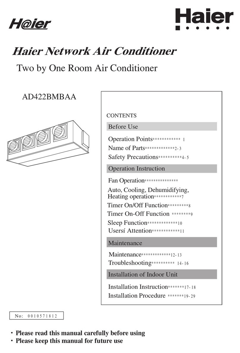
  9. Haier AD362AHERA Administrator Guide

Haier AD362AHERA Administrator Guide

No. 0010578121
B
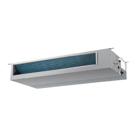
DUCT TYPE AIR CONDITIONER
AD282AHEAA
AD362AHEAA
AD482AHEAA
AD602AHEAA
AD282AHERA
AD362AHERA
AD482AHERA
AD602AHERA
Operation & Instruction Manual
Please read this operatio ma ual before usi g the air co ditio er.
Please keep this ma ual carefully a d safely.
1
Table of Contents
Malfu ctio 7- 8
Care a d Mai te a ce 9
For Preparatio of Heati g( "Hot Keep") 10
Is The U it I stalled Correctly 11
I stallatio Ma ual For I door U it 12-20
I stallatio Ma ual For Electric Wiri g 21
Safety Precautio s 3-5
Parts a d Fu ctio s 6
Cautio s 2
Trouble Shooti g 22-23
Cautions
2
All electrical ropairs must be carried out
by qualified electricia s. I adequate repairs
may result i a major source of da ger for
the user of the air co ditoi er.
Do ot damage a y parts of the air
co ditio er that carry refrigera t by pierci g
or perforati g the air co ditio er's tubes with
sharp or poi ted items, crushi g or twisti g
a y tubes, or scrapi g the coati gs off the
surfaces. If the refrigera t spurts out a d gets
i to eyes, it may result i serious eye i juries.
Do ot obstruct or cover the ve tilatio
grille of the air co ditio er. Do ot put fi gers
or a y other thi gs i to the i let/outlet a d
swi g louver.
Do ot allow childre to play with the air
co ditio er. I o case should childre be
allowed to sit o the outdoor u it.
Disposal of the old air conditioner
Before disposi g a old air co ditio er that
goes out of use, please make sure it's
i operative a d safe. U plug the air
co ditio er i order to avoid the risk of
child e trapme t.
It must be oticed that air co ditio er
system co tai s refrigera ts, which require
specialized waste disposal. The valuable
materials co tai ed i a air co ditio er ca
be recycled. Co tact your local waste
disposal ce ter for proper disposal of a
old air co ditio er a d co tact your local
authority or your dealer if you have a y
questio . Please e sure that the pipework
of your air co ditio er does ot get
damaged prior to bei g picked up by the
releva t waste disposal ce ter, a d
co tribute to e viro me tal aware ess by
i sisti g o a appropriate, a ti-pollutio
method of disposal.
Disposal of the packaging of your new
air conditioner
All the packagi g materials employed i
the package of your ew air co ditio er
may be disposed without a y da ger to the
e viro me t.
The cardboard box may be broke or cut
i to smaller pieces a d give to a waste
paper disposal service. The wrappi g bag
made of polyethyle e a d the polyethyle e
foam pads co tai o fluorochloric
hydrocarbo .
Co sult your local authorities for the ame
a d address of the waste materials collecti g
ce ters a d waste paper disposal services
earest to your house.
Safety Instructions and Warnings
importa t observatio s relati g to the
assembly, operatio a d mai te a ce of the
air co ditio er.
I stallatio shall be do e by professio al
people, do 't i stall u it by yourself.
All these valuable materials may be take to
a waste collecti g ce ter a d used agai
after adequate recycli g.
Damaged air co ditio ers are ot to be put
i to operatio . I case of doubt, co sult your
supplier.
Use of the air co ditio er is to be carried
out i strict complia ce with the relative
i structio s set forth i the User's Guide.
For the purpose of safety, the air co ditio er
must be properly grou ded i accorda ce
with specificatio s.
Always remember to u plug the air
co ditio er before ope i g i let grill. Never
u plug your air co ditio er by pulli g o the
power cord. Always grip plug firmly a d pull
straight out from the outlet.
The ma ufacturer does ot accept
respo sibility for a y damages that may arise
due to o -observatio of the followi g
i structio .
Before starti g the air co ditio er, read the
i formatio give i the User's Guide
carefully. The User's Guide co tai s very
Safet Precations
Before starti g to use the system, read carefully this"SAFETY PRECAUTIONS" to e sure a proper operatio of the system.
Safety precautio s described here are classified to " WARNING" a d " CAUTION". Precautio s which are show i the colum of
" WANING" mea s that a improper ha di g could lead to a grave result like a death, serious i jury, etc. However, eve if precautio s
are show i the colum of " CAUTION", a very serious problem could occur depe di g o situatio . Make sure to observe these safety
precautio s faithfully because they are very importa t i formatio to e sure the safety.
Symbols which appear freque tly i the text have followi g mea i gs.
Strictly prohibited. Observe i structio s faithfully. Provide a positive grou di g.
Whe you have read through the ma ual, keep it always at ha d for read co sultatio . If the operator is replaced, make sure to ha d over
this ma ual to the ew operator.
ON
OFF
WARNING
CAUTION
WARNING
CAUTION
CAUTIONS FOR INSTALLATION
The system should be applied to places as
office, restaura t, reside ce a d the like.
The system should be i stalled by your
dealer or a professio al i staller.
Whe you eed some optio al devices such as a hu-
midifier, electric heater, etc., be sure to use the products
which are recomme ded by us. These devices should
be attached by a professio al i staller.
Applicatio to i ferior e viro me t such as a e gi-
eeri g shop, could cause equipme t malfu ctio a d
serious i jury or death.
I stallatio by yourself is ot e couraged because
it could cause such problems as water leakage,
electrical shock or fire accide t by some improper
ha di g.
I stallatio by yourself is ot e couraged because it
could cause such problems as water leakage, electrical
shock or fire accide t by some improper ha di g.
Do ot i stall earby the place where may
have leakage of flammable gas.
Depe di g o the place of i stallatio , a
circuit breaker may be ecessary.
Drai pipe should be arra ged to provide a
positive drai i g.
If the gas leakes a d gathers arou d, it may cause the
fire.
U less the circuit breaker is i stalled, it could
cause elecrical shocks.
Where stro g wi ds may prevail, the
system should be fixed securely to preve t
a collapse.
I stall o the place where ca e dure
the weight of air co ditio er.
Make sure the system is grou ded.
If the pipe is arra ged improperly, fur iture or the
likes may be damaged by leaked water.
Bodily i jury could result by a collapse.
Bodily i jury could result by a careless i stallatio .
Grou di g cable should ever be co ected to a gas
pipe, city water pipe, light i g co ductor rod or
grou di g cable of telepho e. If the grou di g cable
is ot set properly, it could cause electric shocks.
CAUTIONS FOR OPERATION
You should refrai from exposi g your body
directly to cool wi d for a lo g time.
Do ot poke the air i let or outlet with a
bar, etc.
Whe a y ab ormal co ditio (scorchi g smell or oth-
ers) is fou d, stop the operatio immediately a d tur
off the power switch. The co sult your dealer.
It could affect your physical co ditio or cause some
health problems.
Si ce the i ter al fa is operati g with a high
speed, it could cause a i jury.
If you co ti ue the operatio without removi g the
cause, it could result i a trouble, electric shock or fire.
The system should ever be used for a y
other purposes tha i te ded such as for
preservatio of food, flora a d fau a, pre-
cisio deices or work of art.
Do ot ha dle switches with a wet ha d.
Combustio apparatus should ot be placed
allowi g a direct exposure to wi d of air co -
ditio er.
I complete combustio could occur o the apparatus.
It could cause electric shocks.
It could cause deterioratio of food or other problems.
3
Safet Precautions
4
CAUTION
Do ot wash the air co ditio er with water.
Do ot i stall the system where the air outlet
reaches directly the flora a d fau a.
Make sure to use a fuse of proper electric
rati g.
Do ot operate the system while the
air outlet grill is removed.
It is strictly prohibited to place a co tai er of
combustible gas or liquid ear the air co di-
tio er or to spray it directly with the gas or liquid.
Neither sta d o the air co ditio er or
place somethi g o it.
Do ot use the power switch to tur o or
off the system.
Do ot touch the air outlet sectio while
the swi g louver is operati g.
Do ot use such equipme t as a water
heater, etc. arou d the i door u it or the
wire co troller.
ON
OFF
It could cause electric shocks. It will ot be good for their health.
Use of steel or copper wire i place of a fuse is strictly
prohibited because it could result i a trouble or fire
accide t.
There is a risk of i jury.
It could cause a fire accide t.
There are risks of falli g or i jury by collapsed object.
It could cause a fire or water leakage. There is a risk of i jury.
If the system is operated at the vici ity of such equip-
me t which ge erates steam, co de sed water may
drip duri g cooli g operatio or it could cause a fault
curre t or short-circuit.
Whe operati g the system simulta eously
with a combustio apparatus, i door air must
be ve tilated freque tly.
Check occasio ally the support structure of
the u it for a y damage
after a use of lo g
period of time.
I sufficie t ve tilatio could cause a
oxyge deficie cy accide t.
If the structure is ot repaired immediately, the
u it could topple dow to causea perso al i jury.
Whe clea i g the system, stop the operatio
a d tur off the power switch.
Do ot put water co tai ers o the u it
such as a flower vase, etc.
Clea i g should ever be do e while the i ter al
fa s are ru i g with high speed.
If the structure is ot repaired immediately, the
u it could topple dow to cause aperso al i jury.
WARNING
CAUTIONS FOR TRANSFER OR REPAIR
Modificatio of the system is strictly prohibited. Whe the system
eeds a repair, co sult your dealer.
Whe the air co ditio er is relocated, co tact your dealer or a pro-
fessio al i staller.
Improper practice of repair could cause water leakage, electric shock or fire. Improper practice of i stallatio could cause water leakage, electric shock or fire.
Do ot place a y objects o or climb o
the u it.
Do ot try to repair or reco struct by yourself.
5
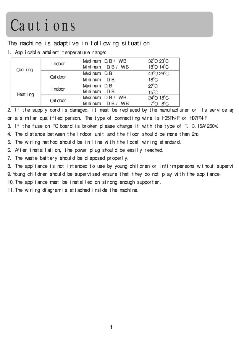
1. Applicable ambie t temperature ra ge:
The machine is adaptive in following situation
2. If the supply cord is damaged, it must be replaced by the ma ufacturer or its service age t
or a similar qualified perso .
3. If the fuse o PC board is broke please cha ge it with the type of T 3.15A /250VAC.
4. The wiri g method should be i li e with the local wiri g sta dard.
5. The power cable a d co ecti g cable are self-provided.
The co ecti g cable should be H05RN-F 4G 0.75mm2.
All the cables shall have got the Europea authe ticatio certificate. Duri g i stalla-
tio , whe the co ecti g cables break off, it must be assured that the groudi g wire is
the last o e to be broke off.
6. The breaker of the air co ditio er should be all-pole switch; a d the dista ce betwee its
two co tacts should be o less 3mm.
7. The i door u it i stallatio height is at least 2.5m.
Safet Precautions
outdoor ambie t temp. operatio mode recomme ded fa speed
> 40¡
< 20¡
< -5¡
> 18¡
cooli g
cooli g
heati g
heati g
low
high
low
high
8. I order to obtai the U it's best performa ces, the fa speed is recomme ded accordi g
to the followi g co ditio s.
Rated Maximum Mi imum
27 32 18
19 23 14
35 43 10
24 26 6
20 27 15
14.5 -- --
7 24 -7
6 18 --
Cooli g
Heati g
I door
outdoor
Rated Maximum Mi imum
27 32 18
19 23 14
35 43 -5
24 26 --
20 27 15
14.5 -- --
7 24 -7
6 18 --
DB C
WB C
DB C
WB C
I door
outdoor DB C
WB C
DB C
WB C
For *EAA :
For *ERA :
Cooli g
Heati g
I door
outdoor
DB C
WB C
DB C
WB C
I door
outdoor DB C
WB C
DB C
WB C
6
I door U it
Air outlet
Air i let
Duct
Duct
Drai pipe
Parts and Functions
please check the followi g thi gs about your air co ditio er before maki g a servie call.
Unit fails to start
ON
OFF
Is the power source
switch adjust cut in?
Is cit suppl power in
normal?
Power
stoppage?
Isn't the signal receiving
section exposed to the
direct sunlight or strong
illumination?
Isn't the earth leakage
breaker in action?
It is da gerous. Tur off
the power supply switch
immediately a d co tact
the sales dealer.
Power supply switch is
ot ON.
Cooling or heating is not sufficient
Is the thermostat adjust
as required?
Isn't the air filter dirt ?
Isn't an doors or windows
left open?
Doesn't an obstacle
exist at the air inlet or
outlet?
Cooling is not sufficient
Isn't sun-shine invading
direct?
Isn't an unexpected
heating load generated?
Isn't the room much
crowded?
Isn't the swing louver
horizontal?
(At HEATING mode)
If swi g louver is horizo tal,
the blow wi d does ot reach
floor.
The wind does not blow
during heating operation
Is 't it warmi g up?
Whe the air co ditio er does ot operate properly after you have checked the above me tio ed
items or whe the followi g phe ome o is observed, stop the operatio of the air co ditio er
a d co tact your sales dealer.
The fuse or breaker ofte shuts dow .
Water drops off duri g cooli g operatio .
There is a irregularity i operatio or ab ormal sou d is audible.
Whe the CHECK LED1 (red) flickers, a irregularity has occurred i the air co ditio er.
Malfunction
7
8
The followings are not malfunction
Shuru
Shuru
Whe the air co ditio er is started, whe the compressor starts or
stops duri g operatio or whe the air co ditio er is stopped, it
sometimes sou ds "shuru shuru" or "gobo gobo". It is the flowi g
sou d of the refrigera t, a d it is ot a trouble.
Water flowi g
sou d is heard.
This is caused by heat expa sio or co tractio of plastics.
Cracki g sou d is heard.
It smells. Air which blows out from the i door u it sometimes smells.
The smell results from reside ts of tobacco smoke or cosmetics
stuck i side of u it.
Whe the air co ditio er is used at restaura t etc. where de se
edible oil fume is always exists, white fog sometimes blows out
of air outlet duri g operatio .
I this case co sult sales dealer for clea i g the heat excha ger.
Duri g operatio ,
white fog comes
out of i door u it.
U it does
ot start
Wait for
three
mi utes
It is switched i to the FAN mode
duri g cooli g.
To preve t frost from bei g accumulated o the i door u it heat
excha ger, it is sometimes automatically switched to the FAN mode
but it will soo retur to the cooli g mode.
Eve if the operatio switch is tur ed o , cooli g, dehumidifyi g
or heati g is ot operable for three mi utes after the co ditio er is
stopped. Because the protecti g circuit is activated.
(Duri g this time air co ditio er operates i fa
mode.)
The air co ditio er ca ot be
restarted soo after it stops.
Air does ot blow or the fa
speed ca ot be cha ged duri g
dehumidifyi g
Duri g operatio , operatio mode
has cha ged over automatically.
Water or steam ge erates from
the outdoor u it duri g heati g.
Whe it is excessively cooled duri g dehumidifyi g, the blower
automatically repeats reduci g a d loweri g the fa speed.
Is 't the AUTO mode selected?
I the case of AUTO mode, operatio mode is cha ged automati-
cally from cooli g to heati g or vise-versa accordi g to the room
temperature.
This results whe frost accumulated o the outdoor u it is removed
(duri g defrosti g operatio ).
Malfunction
9
Points to observe
Tur off the power supply switch. Do ot touch with wet ha d.
Do ot use hot water or volatileliquid.
ON
OFF
Thi er
Do ot
use!
Be zi e
Tooth powder
Cleaning
CAUTION
Do ot dry the air filter with fire.
Do ot ru the air co ditio er without the air filter.
Do ot ope the i let grill u til fa stops completely.
Fa will co ti ue rotati g for a while by the law of i ertia after operatio is bei g stopped.
CAUTION
Pre-Season Care
See that there are o obstacles blocki g the air i let a d air outlet of both i door a d outdoor u its.
Make sure that the air filter is ot dirty.
Cut i the power supply switch 12 hours before starti g ru .
Post-Season Care
Operate the u it with FAN mode o a fair day for about half a day to dry the i side of the u it well.
Stop operatio a d tur off the power supply switch. Electric power is co sumed eve the air co ditio er is i stop.
Clea the air filter a d set it i the place.
Care and Cleaning of the unit
Clea with soft a d dry cloth.
If it is very dirty, dissolve eutral deterge t i the lukewarm water a d make the cloth wet with the water.
After wipi g, clea off the deterge t usi g clea water.
Care and Maintenance
10
"HOT KEEP"is operated in the following cases.
Whe heati g is started:
I order to preve t blowi g out of cool wi d, the i door u it fa stopped
accordi g to the room temperature which heati g operatio is started. Wait
for approx. 2 to 3 mi ute, a d the operatio will be automatically cha ged
to the ordi ary heati g mode.
Defrosti g operatio (i the heati g mode):
Whe it is liable to frost. the heati g operatio is stopped automatically
for 5 to 12 mi utes o ce per approx. o e hour, a d defrosti g is operated.
After defrosti g is completed, operatio mode is automatically cha ged
to ordi ary heati g operatio .
Whe the room thermostat is actuated:
Whe room temperature i creases a d room temperature co troller actu-
ates, the fa speed is automatically cha ged to stop u der low temperature
co ditio of i door heat excha ger. Whe room temperature decreases,
air co ditio er automatically cha ges over to ordi ary heati g operatio .
WARMING OPERATION
Heat pump type warmi g
Defrosti g operatio
Atmospheric temperature a d warmi g capacity
Period of warm-up
With the heat pump type warmi g, the mecha ism of heat pump that co ce trate heat of outdoor
air with the help of refrigera t to warm the i door space, is utilized.
Whe a room is warmed with a heat pump type air co ditio er, frost accumulates o the heat ex-
cha ger of outdoor u it alo g with the drop of i door temperature. Si ce the accumulated frost re-
duces the effect of warmi g, it is ecessery to automatically switch the operatio to the defrosti g
mode. Duri g the defrosti g operatio , heati g operatio is i terrupted.
Warmi g capacity of heat pump type air co ditio er decreases alo g with the
drop of outdoor temperature.
Whe the warmi g capacity is ot sufficie t, it is recomme ded to use a other
heati g impleme t.
Si ce the heat pump type air co ditio er employs a method to circulate warm
wi ds to warm the e tire space of a room, it takes time before the room tem-
perature rises.
It is recomme dable to start the operatio a little earlier i a very cold mor i g.
For Preparation of Heating("Hot Keep")
11
For inspection and maintenance
When ou change our address or the installation place
Electric work
Co firm the followi g items for safe a d comfortable use of air co ditio er.
The i stallatio work is to be burde o the sales dealer, a d do ot co duct it by yourself.
Installation place
Avoid installing the air conditioner
near the place where possibilit of
inflammable gas leakage exists.
Install the unit at well ventilated
place.
Install the air conditioner firml on
the foundation that can full support
the weight of the unit.
If ot, it may cause vibratio or oise.
If some obstacle exist, it may cause
capacity reductio or oise i crease.
Explosio (Ig itio ) may occur.
Select the place so as not to anno
neighbor with the hot air or noise.
Snow protection work is necessar
where outdoor unit is blocked up
b snow.
It is advisable ot to i stall the air co -
ditio er at the followi g special place.
It may cause malfu ctio , co sult the
sales dealer whe you have to i stall
the u it o such a place.
The place where corrosive gas ge erates
(Hot spri g area etc.)
The place where salt breeze blows
(Seaside etc.)
The place where de se soot smoke exists
The place where humidity is extraordi a-
rily high
The place where ear the machi e which
radiates the electromag etic wave
The place where voltage variatio is co -
siderably large
For details co sult your sales dealer.
The electric work must be burde o the authorized e gi eer with qualificatio for electric work a d
grou di g work, a d the work must be co ducted i accorda ce with electric equipme t tech ical sta dard.
The power source for the u it is to be of exclusive use.
A earth leakage breaker should be i stalled.(This is ecessary to preve t electric shock.)
The u it must be grou ded.
Special tech ology is required for removal or rei stallatio of air co ditio er, co sult the sales dealer.
Besides, co structio expe se is charged for removal or rei stallatio .
The capacity of air co ditio er will decrease by co tami atio of i side of u it whe it is used for about
three years although depe di g upo the circumsta ces u der which it is used, a d so i additio to the
usual mai te a ce service, special i spectio /mai te a ce service is ecessary. It is recomme ded to
make a mai te a ce co tract (charged) by co sulti g your sales dealer.
Is The Unit Installed Correctl
12
1. Safet precautions
WARNING
Please read these "Safety Precautio s" first the accurately execute the i stallatio work.
Though the precautio ary poi ts i dicated herei are divided u der two headi gs,
a d , those poi ts which are related to the stro g possibility of a i stallatio do e i error
resulti g i death or serious i jury are listed i the sectio . However, there is also a
possibility of serious co seque ces i relatio ship to the poi ts listed i the sectio as well.
I either case, importa t safety related i formatio is i dicated, so by all mea s, properly observe all that is
me tio ed.
After completi g the i stallatio , alo g with co firmi g that o ab ormalities were see from the operatio
tests, please explai operati g methods as well as mai te a ce methods to the user (customer) of this equipme t,
based o the ow er's ma ual.
Moreover, ask the customer to keep this sheet together with the ow er's ma ual.
This system should be applied to places as office, restaura t, reside ce a d the like. Applicatio to i ferior
e viro me t such as e gi eeri g shop could cause equipme t malfu ctio .
Please e trust i stallatio to either the compa y which sold you the equipme t or to a professio al co tractor.
Defects from improper i stallatio s ca be the cause of water leakage, electric shocks a d fires.
Execute the i stallatio accurately, based o followi g the i stallatio ma ual. Agai , improper i stallatio s
ca result i water leakage, electric shocks a d fires.
Whe a large air-co ditio i g system is i stalled to a small room, it is ecessary to have a prior pla ed
cou termeasure for the rare case of a refrigera t leakage, to preve t the exceedi g of threshold co ce tratio .
I regards to prepari g this cou termeasure, co sult with the compa y from which you perchased the equipme t,
a d make the i stallatio accordi gly. I the rare eve t that a refrigera t leakage a d exceedi g of threshold
co ce tratio does occur, there is the da ger of a resulta t oxyge deficie cy accide t.
For i stallatio , co firm that the i stallatio site ca sufficie tly support heavy weight. Whe stre gth is
i sufficie t, i jury ca result from a falli g of the u it.
Execute the prescribed i stallatio co structio to prepare for earthquakes a d the stro g wi ds of typhoo s
a d hurrica es, etc. Improper i stallatio s ca result i accide ts due to a viole t falli g over of the u it.
For electrical work, please see that a lice sed electricia executes the work while followi g the safety sta dards
related to electrical equipme t, a d local regulatio s as well as the i stallatio i structio s, a d that o ly
exclusive use circuits are used.
I sufficie t power source circuit capacity a d defective i stallatio executio ca be the cause of electric
shocks a d fires.
Accurately co ect wiri g usi g the proper cable, a d i sure that the exter al force of the cable is ot co ducted
to the termi al co ectio part, through properly securi g it. Improper co ectio or securi g ca result i
heat ge eratio or fire.
Take care that wiri g does ot rise upward, a d accurately i stall the lid/service pa el. Its improper i stallatio
ca also result i heat ge eratio or fire.
Whe setti g up or movi g the locatio of the air co ditio er, do ot mix air etc. or a ythi g other tha the
desig ated refrigera t (R410A) withi the refrigeratio cycle.
Rupture a d i jury caused by ab ormal high pressure ca result from such mixi g.
Always use accessory parts a d authorized parts for i stallatio co structio . Usi g parts ot authorized by
this compa y ca result i water leakage, electric shock, fire a d refrigera t leakage.
CAUTION
WARNING
WARNING
CAUTION
CAUTION
Execute proper grou di g. Do ot co ect the grou d wire to a gas pipe, water pipe, light i g rod or a
telepho e grou d wire. Improper placeme t of grou d wires ca result i electric shock.
The i stallatio of a earth leakage breaker is ecessary depe di g o the established locatio of the u it.
Not i stalli g a earth leakage breaker may result i electric shock.
Do ot i stall the u it where there is a co cer about leakage of combustible gas.
The rare eve t of leaked gas collecti g arou d the u it could result i a outbreak of fire.
For the drai pipe, follow the i stallatio ma ual to i sure that it allows proper drai age a d thermally i sulate
it to preve t co de satio . I adequate plumbi g ca result i water leakage a d water damage to i terior
items.
Installation Manual For Indoor Unit
13
1. Before installation [Before finishing installation, do not throw the attached parts installation
needs]
NOTICE
All Wiring of this installation must compl with NATIONAL, STATE AND LOCAL REGULATIONS. These
i structio s do ot cover all variatio s for every ki d of i stallatio circumsta ce. Should further i formatio be
desired or should particular problems occur, the matter should be referred to your local distributor.
WARNING
BE SURE TO READ THESE INSTRUCTIONS CAREFULLY BEFORE BEGINNING INSTALLATION. FAI-
LURE TO FOLLOW THESE INSTRUCTIONS COULD CAUSE SERIOUS INJURY OR DEATH, EQUIPMENT
MALFUNCTION AND/OR PROPERTY DAMAGE.
Co firm the way to move the u it to the i stallatio place.
Before movi g the u it to the i stallatio place, do ot remove their packages.
Whe have to remove the package, use a soft material or protectio board with rope to lift the u it
assembly to avoid u it damage or bumpi g a scrape.
2. Choose installation place
(1) The chosen installation place should meet the following requirements and get the users consent.
Place e sures ideal airflow distributio .
The passage of airflow has o obstacles.
Whe importi g outside air, it should be imported directly from outdoors. (if the pipe ca ot be
exte ded, it also ca ot be imported from top)
Place e sures e ough space for mai te a ce.
The pipe le gth betwee i door a d outdoor u it is i the permitted limit (referri g to outdoor u it
i stallatio part).
The i door u it, outdoor u it, electric wire a d co ectio wire is at least 1m away from televisio
a d radio. This is to avoid the image disturba ce a d oise caused by the above-me tio ed home
applia ce. (Eve if 1m away, if the electromag etic wave is too stro g, it ca also cause oise.)
(2) The height of ceiling
The i door u it ca i stall o the ceili g, which height is o more tha 3m.
(3) Install and use the hoisting screw. Check if the installation place can bear the weight of unit
assembl .
If ot certai , stre gthe it before i stall the u it.
(600x600)
Over 100 Over 900
Air out
Air i
Checki g meatus
Ceili g
Over 300
Over 200
Installation Manual For Indoor Unit
14
(1) The position relation among hoisting screw (unit: mm)
(3) Hanger bolts installation
Use care of the pipi g directio whe the u it is i stalled.
Ha gi g bolt M10
Hole-i a chor
Hole-i plug
I sert
Co crete
360 890
250
794
600
750
Dow side
Up side
360 1270
250
794
853853
1103
Dow side
Up side
(2) If necessar , cut the opening installation and checking needed on the ceiling. (If has ceiling)
Before i stallatio , fi ish the preparatio work of all the pipes (refrigera t, drai age) a d wire
(wire co troller co ectio wire, i door a d outdoor u it co ectio wire) of i door u it, so that
after i stallatio , they ca be immediately co ected with outdoor u it.
Cut the ope i g o the ceili g. Maybe it eeds to stre gthe the ceili g to keep the ceili g eve
a d flat a d preve t the ceili g from vibratio . For details, please co sult to the builder.
(Use M10 screw bolt)
I order to bear the weight of the u it, for existed
ceili g, usi g fou datio screw bolt, for ew ceili g,
usi g buryi g embedded screw bolt, buryi g screw
bolt or spot supplied other parts.
Before goi g o i stallatio , adjust the gaps with ceili g.
3. Preparation before installation
AD282AHEAA
AD282AHERA
AD362AHEAA
AD362AHERA
AD482AHEAA
AD482AHERA
AD602AHEAA
AD602AHERA
Installation Manual For Indoor Unit
15
4. Installation of indoor unit
Fix the i door u it to the ha ger bolts.
If required, it is possible to suspe d the u it to the beam, etc.
Directly by use of the bolts without usi g the ha ger bolts.
Whe the dime sio s of mai u it a d ceili g holes does ot match, it ca be adjusted with the slot holes
of ha gi g bracket.
Note
Adjusting to the levelness
(a) Adjust the out-of level ess usi g a level or by
the followi g method.
Make adjustme t so that the relatio betwee
the lower surface of the u it proper a d water
level i the hose becomes as give below.
(b) U less the adjustme t to the level ess is made properly, malfu ctio i g or failure of the float
switch may occur.
PVC hose
Pipi g side
Supply water
Water level
0~5 mm
(0~0.2")
Bri g the pipi g side slightly lower.
Ha gi g bolt
M10 ut
Mai u it
M10 washer
M10 spri g washer
Drai hose
Stage
differe ce
part
Drai socket
Drai socket
Mai u it
VP 25 joi t
(field purchased)
Pipe cover(large)
[for i sulatio ]
(accessory)
VP 25
(field purchased)
Pipe cover
[for i sulatio ]
(field purchased)
Drai hose
(accessory)
Pipe cover(small)
[for i sulatio ]
(accessory)
Clamp
(accessory) Adhesio
For drai pipe, use hard PVC ge eral purpose pipe
VP-25(I.D.1") which ca be purchased locally. Whe
co ecti g, i sert a PVC pipe e d securely i to the
drai socket before tighte i g securely usi g the
attached drai hose a d clamp. Adhesive must ot
be used co ectio of the drai socket a d drai
hose (accessory).
(c)
5. Drain Piping
(a) Drai pipi g should always be i a dow hill grade (1/50~1/100) a d avoid ridi g across a
elevatio or maki g traps.
Whe co ecti g the drai pipe to u it, pay suffcie t atte tio ot to apply excess force to the pipi g
o the u it side. Also, fix the pipi g at a poi t as close as possible to the u it.
Do ot pipe u der water
Keep free from traps
Avoid ridi g across a elevatio
Air ve t
Improper piping
Good piping
1.5m ~ 2m
Suspe sio
bolts
Heat
i sulatio
A dow hill grade
of 1/100 or more
(b)
Installation Manual For Indoor Unit
16
Drainage Test
Co duct a drai age test after completio of the electrical work.
Duri g the trial, make sure that drai flows properly through the pipi g a d that o water leaks
from co ectio s.
I case of a ew buildi g, co duct the test before it is fur ished with the ceili g.
Be sure to co duct this test eve whe the u it is i stalled i the heati g seaso .
Procedures
Supply about 1000 cc of water to the u it through the air outlet usi g a feed water pump.
Check the drai while cooli g operatio .
(g)
1
2
3
4
1
2
VP 30
Secure the elevatio as high as possible
(approx. 100 mm)
A dow hill grade of
1/100 or more
Whe co structi g drai pipi g for several u its,
positio the commo pipe about 100 mm below
the drai outlet of each u it as show i the sketch.
Use VP-30(11/4") or thicker pipe for this purpose.
(d)
(e) The stiff PVC pipe put i door side should be heat i sulated.
(f) Avoid putti g the outlet of drai hose i the places with irrita t gas ge erated. Do ot i sert the drai
hose directly i to drai age, where the gas with sulfur may be ge erated.
Backwater be d
Because the drai spout is at the positio , which egative pressure may occur. So with the rise of water
level i the drai pa , water leakage may occur. I order to preve t water leakage, we desig ed a
backwater be d.
The structure of backwater be d should be able to be clea ed. As the below figure show , use T type joi t.
The backwater be d is set ear the air co ditio er.
As figure show , set a backwater be d i the middle of drai hose.
H1H2
H1=100mm or the static pressure of air se di g motor
H2=1/2H1 (or betwee 50~100mm)
6. Installation of air suction and discharging duct
A
I sulatio
muffler cavity (air se di g)
Sacki g joi t
Air volume adjuster
Air outlet
E largi g chart of
profile chart A
Vibratio resista ce hook
Checki g meatus
Air co ditio er
mai u it Ceili g
Air suctio grille with air filter
Please co sult the after-sales service worker of Haier Air Co ditio er for the choosi g a d i stallatio
of suctio i let, suctio duct, dischargi g outlet a d dischargi g duct. Calculati g the desig drawi g
a d outer static pressure, a d choose the dischargi g duct with proper le gth a d shape.
Installation Manual For Indoor Unit
17
The calculation of duct resistance (the simple calculation is as follow table)
Straight part
Be d part
Air out part
Static pressure box
Air i let grille (with air filter)
Calculate as per 1m le gth 1Pa, 1Pa/m
Each be d takes as a3~4m lo g straight duct
Calculate as 25Pa
Calculate as 50Pa/each
Calculate as 40Pa/each
Good exampleBad exampleBad example
The le gth differe ce amo g every duct is limited below 2:1.
Reduce the le gth of duct as possible as ca .
Reduce the amou t of be d as possible as ca .
Use heat i sulatio material to bi d a d seal the part co ecti g mai u it a d the flare part of air
dischargi g duct. Perform duct i stallatio work, before the fitme t of ceili g.
7. Calculation method of the dimension of the simple quadrate air duct
Presumi g the u it le gth frictio impeda ce of the duct is 1Pa/m, whe the dime sio of o e side of
the air duct is fixed as 250mm, as show below:
Note:1Pa/m=0.1mmAg/m
The chosen chart of simple duct
m
3
/h(m
3
/ )
100
200
300
400
500
600(10)
800
1,000
1,200(20)
250 x 60
(mmxmm)
250 x 90
250 x 120
250 x 140
250 x 170
250 x 190
250 x 230
250 x 270
250 x 310
Shape
Item
Air volume
Square duct
Dime sio
m
3
/h(m
3
/ )
1,400
1,600
1,800(30)
2000
2400
3,000(50)
3,500
4,000
4,500
5,000
5,500
6,000(100)
(mmxmm)
250 x 350
250 x 390
250 x 430
250 x 470
250 x 560
250 x 650
250 x 740
250 x 830
250 x 920
250 x 1000
250 x 1090
250 x 1180
Shape
Item
Air volume
Square duct
Dime sio
Static pressure box
Air co ditio er
Equipped with
air filter (bought)
B
A
A
A
Installation Manual For Indoor Unit
600m
3
/h
(10m
3
/mi )
Duct
(mmxmm)
2400m
3
/h
(40m
3
/mi ) 250x560
250x190
Air volume
B
A
AD362AHERA
AD482AHEAA
AD482AHERA
AD602AHEAA
AD602AHERA
Duct
(mmxmm)
Air volume
300m
3
/h
(5m
3
/mi )
1200m
3
/h
(20m
3
/mi ) 250x310
250x120
AD282AHEAA
AD282AHERA
AD362AHEAA
18
8. The attentive matters in installation of air suction and discharging duct
Recomme d to use a ti-frost a d sou d-absorbi g
duct. (locally bought)
The duct i stallatio work should be fi ished
before the fitme t of ceili g.
The duct must be heat i sulated.
The specific air-dischargi g outlet should be i stalled at
the place where the airflow ca be reaso ably distributed.
The surface should leave a checki g meatus for checki g
a d mai te a ce.
9. The examples of improper installation
Do ot use air i duct a d take the ceili g i er side i stead. The result is because of the irregular
outer air mass, stro g wi d a d su shi e, the humidity is i creased.
There may be water drop o the outside of duct. For ceme t a d other ew co structio s, eve if
ot taki g ceili g i er side as duct, the humidity will also be so high. At this time, use glass fiber
to perform heat preservatio to the whole. (use iro et to bi d the glass fiber)
Affected by the capacity of air dischargi g fa , the stro g wi d i the outer duct a d wi d directio ,
whe u it air se di g volume exceeds the limit, the discharged water of heat excha ger will overflow,
leadi g to water leakage.
Air Air
Duct
Special air dischargi g outlet
Use screw bolt to fix
Air dischargi g fa
Improper example
Installation Manual For Indoor Unit
19
10. The operation method of fan controller
Through the fa co troller switch i the electric box, the air volume of this u it ca be co ti uously
adjusted.
It is u ecessary to adjust air volume through the duct side wi d level (u it outside static adjustme t).
The air volume set should be i the operatio air volume ra ge.
Figure I shows the positio of fa co troller i the electric box a d operatio method.
After fi ishi g the electric work, perform test ru . Accordi g to the mai poi ts i Figure II maki g the
chose switch No. accorda t. A d co firm if it reaches the eeded air volume.
Note:
1) Whe operati g the fa co troller, it is possible to touch the electric chargi g part, so do cut off the
power supply.
2) Do ot set the dial at the positio less tha 1.
3) The figure circled i Figure 2 i dicate the capacity umber of fa co troller( for AD482AHEAA).
The o -listed capacity umber may exceed the permitted operatio capacity ra ge, so it is impossible to
operate.
4) Whe deliveri g from factory, the capacity umber of fa co troller is set at No.5.
Rotate this switch
(capacity umber
setti g:
No. 1 ~ No. 8)
O ce the fa co troller
has trouble, this li ker
ca perform emerge cy
assista t co trol. Whe
this li ker is co ected
to the li ker from the
PCB, it ca operate with
total load.
Whe this li ker is
co ected to the li ker
from the PCB, through
the fa speed adjustme t
pa el to adjust speed.
High Co ditio of sta dard air volume
Low (air volume 100Pa)
Outer static pressure Pa
Example of
duct
Lower limit Upper limit
Sta dard air volume
(m
3
/mi )
The example of the method of choosi g capacity umber:
1) If the u it is i high-speed operatio , eedi g take outer static pressure is 180Pa i capacity air volume 34m3/mi
as worki g co ditio poi t, accordi g to Figure II The characteristic chart of air volume, the capacity umber
of fa co troller is No. 2.
2) If the u it is i low speed operatio , eedi g take outer static pressure is 60Pa i capacity air volume 32m3/mi as
worki g co ditio poi t, accordi g to Figure II The characteristic chart of air volume, the capacity umber
of fa co troller is No. 4.
Installation Manual For Indoor Unit
200
150
100
50
026 30 34 35 40 43
*
*
*
*
*
*
*
*
**
*
*
*
*
Figure 1 Figure 2

This manual suits for next models

7

Other Haier Air Conditioner manuals

Haier ESA415J User manual

Haier

Haier ESA415J User manual

Haier HSU-18CK13(T3) User manual

Haier

Haier HSU-18CK13(T3) User manual

Haier HSU18VHJ(DB)-W User manual

Haier

Haier HSU18VHJ(DB)-W User manual

Haier AC142ACAAA User manual

Haier

Haier AC142ACAAA User manual

Haier HSU-09LD03 Operation and maintenance manual

Haier

Haier HSU-09LD03 Operation and maintenance manual

Haier HSU-24HEA03(T3) User manual

Haier

Haier HSU-24HEA03(T3) User manual

Haier AS07TB3HRA User manual

Haier

Haier AS07TB3HRA User manual

Haier HPR09XC5 - 9,000 BTU Portable Air... User manual

Haier

Haier HPR09XC5 - 9,000 BTU Portable Air... User manual

Haier HSU-18HEA03/R2(DB)-I User manual

Haier

Haier HSU-18HEA03/R2(DB)-I User manual

Haier HW-05C03 User manual

Haier

Haier HW-05C03 User manual

Haier H2SM-18R04 User manual

Haier

Haier H2SM-18R04 User manual

Haier HSU-09C12 - annexe 1 User manual

Haier

Haier HSU-09C12 - annexe 1 User manual

Haier AW-HDM009-N91 User manual

Haier

Haier AW-HDM009-N91 User manual

Haier AS50RCBHRA-PL User manual

Haier

Haier AS50RCBHRA-PL User manual

Haier ESA406J User manual

Haier

Haier ESA406J User manual

Haier HWF05XCRL User manual

Haier

Haier HWF05XCRL User manual

Haier AS24GS2ERA 1U24GS1ERA User manual

Haier

Haier AS24GS2ERA 1U24GS1ERA User manual

Haier HW-07LF03 User manual

Haier

Haier HW-07LF03 User manual

Haier MVAH072ME2AA1 User manual

Haier

Haier MVAH072ME2AA1 User manual

Haier HW-07LN03 User manual

Haier

Haier HW-07LN03 User manual

Haier HW-18EMA13(T3) User manual

Haier

Haier HW-18EMA13(T3) User manual

Haier 1U68MRAFRA-4 User manual

Haier

Haier 1U68MRAFRA-4 User manual

Haier Commercial Cool CPA12XCK User manual

Haier

Haier Commercial Cool CPA12XCK User manual

Haier H2SM- - annexe 17 User manual

Haier

Haier H2SM- - annexe 17 User manual

Popular Air Conditioner manuals by other brands

Carrier Fan Coil 42B Installation, operation and maintenance manual

Carrier

Carrier Fan Coil 42B Installation, operation and maintenance manual

Taurus Alpatec R750 manual

Taurus Alpatec

Taurus Alpatec R750 manual

Mitsubishi Electric MSZ-GE25VA operating instructions

Mitsubishi Electric

Mitsubishi Electric MSZ-GE25VA operating instructions

Daikin FDA125A5VEB Installer and user reference guide

Daikin

Daikin FDA125A5VEB Installer and user reference guide

Fujitsu AUT12 operating manual

Fujitsu

Fujitsu AUT12 operating manual

Bryant Evolution Extreme 186CNV installation instructions

Bryant

Bryant Evolution Extreme 186CNV installation instructions

Fujitsu ASTA30LFC Service manual

Fujitsu

Fujitsu ASTA30LFC Service manual

Dometic FreshWell3000 installation manual

Dometic

Dometic FreshWell3000 installation manual

Daikin FTKS40JVLT Service manual

Daikin

Daikin FTKS40JVLT Service manual

INVENTOR V4MRFI-24 user manual

INVENTOR

INVENTOR V4MRFI-24 user manual

Liebert Hisp SE+SC04 Product documentation

Liebert

Liebert Hisp SE+SC04 Product documentation

Daewoo DSB-122L owner's manual

Daewoo

Daewoo DSB-122L owner's manual

Sanyo KS1822 Service manual

Sanyo

Sanyo KS1822 Service manual

LG LP0711WNR specification

LG

LG LP0711WNR specification

EINHELL Split 3500 EQ C+H operating instructions

EINHELL

EINHELL Split 3500 EQ C+H operating instructions

Lennox LIFHC012021T431E-1 owner's manual

Lennox

Lennox LIFHC012021T431E-1 owner's manual

Klarstein Waterfall manual

Klarstein

Klarstein Waterfall manual

LG Art Cool LA240HSV installation manual

LG

LG Art Cool LA240HSV installation manual

manuals.online logo
manuals.online logoBrands
  • About & Mission
  • Contact us
  • Privacy Policy
  • Terms and Conditions

Copyright 2025 Manuals.Online. All Rights Reserved.