Halfen HSD User manual

Assembly Instructions • Montageanleitung •Instrukcja montażu • Instruções de Montagem •
Monteringsanvisning
HALFEN HSD INST_HSD 06/13
Shear dowel system
Schubdornsystem
Trzpienie dylatacyjne
Conectores de Juntas
de Dilatação
Tvärkraftsdorn

HSD-CRET Heavy duty shear dowel
The HSD-CRET Sleeves are nailed to the formwork using
the nailing plate (fi gure 1 and 2); the sleeves must be
placed exactly horizontal. The protective cover prevents
concrete seeping into the sleeve and must not be removed.
It is important that the additional reinforcement is installed
according to the engineer’s specifi cation and the reinforce-
ment drawings.
After removing the formwork for the fi rst concreting sec-
tion the joint fi ller is fi xed in place (fi gure 3). The joint
width must be exactly as specifi ed in the plans. The posi-
tions of the HSD-CRET Sleeves are then marked on the
joint fi ller, or appropriate size holes are made in the joint
fi ller to allow the HSD-CRET Shear dowel to be inserted
into the HSD-CRET Sleeves. The HSD-CRET Shear dowel
complies with DIN 1045-1 or DIN EN 1992-1-1, corrosion
protection requirements. For higher protection require-
ments the dowel and the sliding sleeve can be greased with
a suitable corrosion protection material, e.g. petralat based.
If the reinforcement drawing stipulates better fi re protec-
tion the HSD-F Fire protection pad must be installed;
installation is as shown in fi gure 5b, → see next page.
2nd Concreting phase
1st Concreting phase
3
2
1
Additional reinforcement (by contractor)
4
Joint width
Front viewSection
Filler
HSD-CRET
Shear dowel
sleeve
1st Concreting phase 2nd Concreting phase
HSD-CRET
Shear dowel
Offi cially approved
DIBt: Z-15.7-253
F.J. Aschwanden AG
CH-3250 Lyss
Z-15.7-253
Schubdorne
Cret®
Serie 100
Dowel, Sleeve, Load distribution body,
Nailing plate for fi xing the sleeve to the fomwork
2© 2013 HALFEN · INST_HSD 06/13 · www.halfen.com
HALFEN HSD Assembly Instructions
Deutsch EnglishSvenska PolskiPortuguês

6
5b
5a
4
3
2
1
HSD-F Fire protection pad
HSD Single shear dowel
2nd Concreting phase
1st Concreting phase
6. Reinforcement
Install the additional reinforcement specifi ed for the
shear dowel (by contractor) and the reinforcement for
the main structure.
Concrete the 2nd section.
1. Fix the HSD Sleeve to the formwork
Nail the HSD Sleeve to the formwork at the specifi ed
position. Important: the sleeve must be aligned exactly
in the direction of sliding.
NOTE: Do not remove the label; the label prevents
concrete seeping into the sleeve.
2. Reinforcement
Install the additional reinforcement specifi ed for the
shear dowel (by contractor) and the reinforcement for
the main structure.
Concrete the 1st section.
5a. Shear dowel
Insert the HSD-D Shear dowel through the joint fi ller
into the HSD Sleeve; the dowel should touch the
bottom of the sleeve (safety plug).
5b. Shear dowel with fi re protection pad acc. to DIN 4102
Insert the shear dowel into the sleeve as shown in 5a.
A recess must be made in the joint fi ller to accomodate
the HSD-F Fire protection pad. The fi re protection pad
is placed on the shear dowel as shown in the drawing
below.
3. Joint fi ller
Place the joint fi lling material against the fi rst concrete
section.
4. Mark the positions of the sleeves
If required mark the exact positions of the HSD Sleeves.
3
© 2013 HALFEN · INST_HSD 06/13 · www.halfen.com
HALFEN HSD Assembly Instructions
Deutsch EnglishSvenska Polski
Português

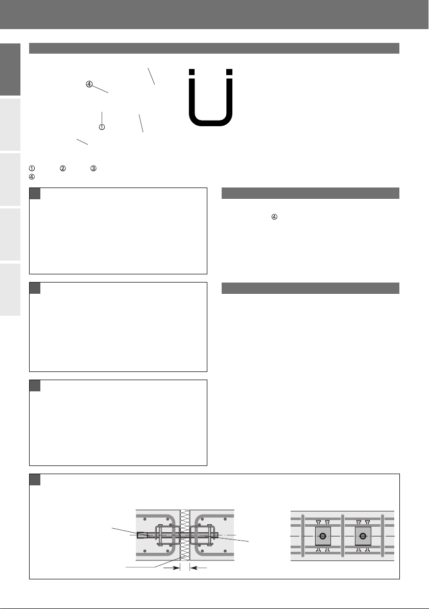
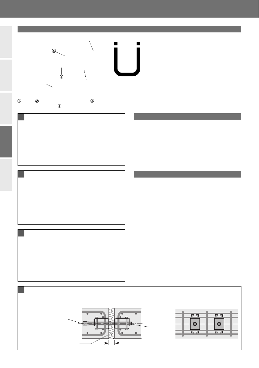
HSD-CRET Schwerlastschubdorn
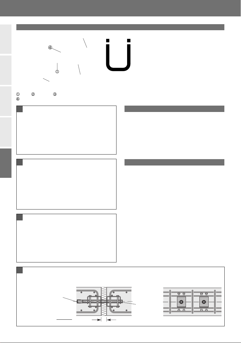
Fugenbreite
FrontalansichtSeitenansicht
Füllmaterial
HSD-CRET
Schubdorn-
Hülse
1. Betonierabschnitt 2. Betonierabschnitt
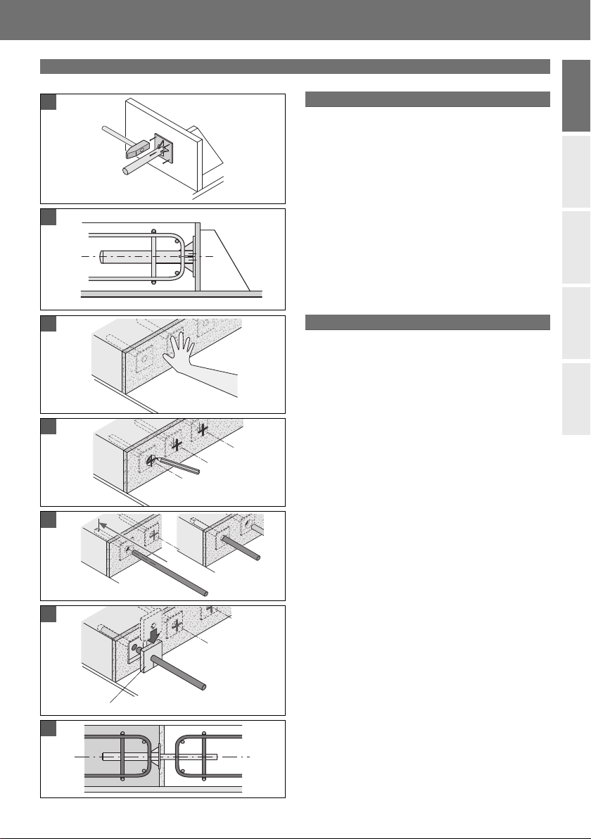
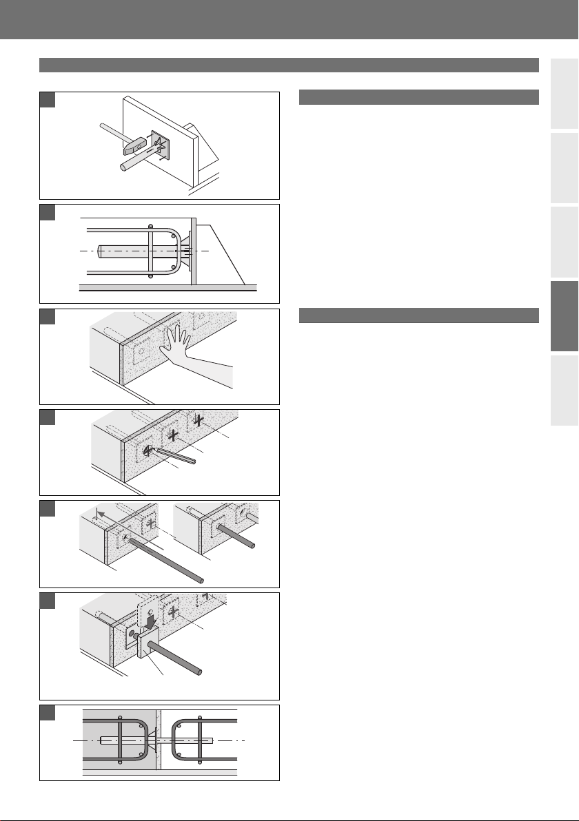
Die HSD-CRET Hülsen sind mittels der Nagelplatte auf
die Schalung zu nageln (Bilder 1 u. 2); dabei ist auf die ho-
rizontale Lage der Hülsen zu achten. Der Schutzaufkleber
darf nicht entfernt werden, da er das Eindringen von Beton
in die Hülsen während des Betoniervorganges verhindert.
Die gemäß den Angaben des Statikers und dem Beweh-
rungsplan angegebene bauseitige Zusatz- und Aufhänge-
bewehrung ist unbedingt einzubauen.
Nach dem Ausschalen des ersten Betonierabschnittes wird
das Füllmaterial in die Fuge eingelegt (Bild 3). Die im Plan
angegebene Fugenbreite ist genau einzuhalten. Die Positi-
onen der Hülsen sind zu markieren bzw. das Füllmaterial ist
ggf. auszusparen, so dass die Dorne in die Hülse eingeführt
werden können. Die erforderliche Zulagebewehrung ist ent-
sprechend den Angaben des Statikers und der Bewehrungs-
pläne einzubauen. Die Verwendung der Schubdorne ist
ohne weitere Maßnahmen für Umweltbedingungen
gemäß DIN 1045-1 bzw. DIN EN 1992-1-1 zulässig. Bei
Umweltbedingungen mit höheren Anforderungen an den
Korrosionsschutz sind Dorne und Gleithülse satt mit einer
Korrosionsschutzmasse, z. B. auf Petrolatebasis, einzustrei-
chen. Werden besondere Anforderungen an die Feuerwider-
standsdauer gemäß den Angaben im Bewehrungsplan ge-
stellt, ist die HSD-F Brandschutzmanschette einzusetzen;
die Montage erfolgt sinngemäß wie in Bild 5b dargestellt,
→ siehe nächste Seite.
2. Betonierabschnitt
1. Betonierabschnitt
HSD-CRET
Schubdorn
Bauaufsichtlich
zugelassen
DIBt: Z-15.7-253
F.J. Aschwanden AG
CH-3250 Lyss
Z-15.7-253
Schubdorne
Cret®
Serie 100
3
2
1
4
Dorn, Gleithülse, Lastverteilkörper, Nagelplatte
zur Befestigung der Hülse an der Schalung
Zulage- und Aufhängebewehrung (bauseits)
4© 2013 HALFEN · INST_HSD 06/13 · www.halfen.com
Deutsch English
HALFEN HSD Montageanleitung
Svenska PolskiPortuguês

6
5b
5a
4
3
2
1
HSD Einzelschubdorne
Zweiter Betonierabschnitt
Erster Betonierabschnitt
6. Bewehrung
Verlegen der bauseitigen Zulage- und Rückhänge-
bewehrung sowie der Bauteilbewehrung.
Betonieren des 2. Abschnitts.
1. Befestigen der Hülse
HSD Hülse gemäß vorgesehener Position an die Scha-
lung nageln. Wichtig: Die Hülse muss exakt in Gleitrich-
tung ausgerichtet sein.
HINWEIS: Aufkleber nicht entfernen. Dieser schützt die
Hülse gegen das Eindringen von Frischbeton.
2. Bewehrung
Verlegen der bauseitigen Zulage- und Rückhängebeweh-
rung sowie der Bauteilbewehrung.
Betonieren des 1. Abschnitts.
5a. Schubdorn
Der zur HSD Hülse passende Schubdorn HSD-D ist nun
durch das Fugenmaterial hindurch einzuführen und
bis zum Anschlag (Sicherheitsstopfen) in die Hülse zu
schieben.
5b. Schubdorn mit Brandschutzmanschette
Bei Brandschutzanforderungen gem. DIN 4102 ist für
die Brandschutzmanschette HSD-F eine Aussparung im
Fugenmaterial vorzusehen. Die Brandschutzmanschette
wird auf den Schubdorn aufgesteckt, wie dargestellt.
Einsetzen des Schubdorns in die Gleithülse wie unter
5a beschrieben.
3. Fugenmaterial
Anbringen des Fugenmaterials.
4. Markierung der Hülsenpositionen
Die Positionen der HSD Hülsen sind gegebenenfalls
genau zu markieren.
Brandschutzmanschette HSD-F
5
© 2013 HALFEN · INST_HSD 06/13 · www.halfen.com
Deutsch English
HALFEN HSD Montageanleitung
Svenska Polski
Português

HSD-CRET Trzpienie dylatacyjne
Szerokość dylatacji
Przekrój podłużnyPrzekrój poprzeczny
Zbrojenie dodatkowe i podwieszające
Materiał wypełniający
Zbrojenie krawędziowe
i podwieszające
1. etap betonowania 2. etap betonowania
Elementy HSD-CRET z tuleją przybić do szalunku
(rys. 1 i 2); Zwrócić uwagę na poziome usytuowanie tulei.
Taśma ochronna nie może być usunięta, ponieważ chroni
tuleję podczas betonowania przed wniknięciem mieszanki
betonowej. Na budowie bezwzględnie uzupełnić zbrojenie
o dodatkowe i podwieszające wg danych konstruktora i
planu zbrojenia.
Po demontażu szalunku pierwszego etapu betonowania,
ułożyć materiał wypełniający dylatację (rys. nr 3). Szerokość
szczeliny dylatacyjnej musi być zgodna z projektem. Zaznaczyć
położenie tulei i ewentualnie wyciąć otwory w materiale
wypełniającym w ten sposób, aby trzpienie mogły być
wprowadzone w tuleje. Wbudować wymagane dodatkowe
zbrojenie zgodnie z danymi konstruktora i planem zbrojenia.
Przy podwyższonych wymaganiach w zakresie ochrony
korozyjnej, trzpienie i tuleje zabezpieczyć masą ochronną.
Przy szczególnych wymaganiach w zakresie odporności
ogniowej, należy zastosować wkładkę ognioochronną HSD-F.
Montaż przeprowadzić zgodnie z rys. 5b.
CERTYFIKAT
ZAKŁADOWEJ KONTROLI
PRODUKCJI ITB-0366/Z
=$.â$'2:$
.21752/$
352'8.&-,
Aprobata Techniczna
ITB nr. AT-15-5264/2012
Drugi etap betonowania
Pierwszy etap betonowania
HSD-CRET
Trzpień
3
2
1
4
Trzpieñ, Tuleja, Korpus, Blacha czołowa z
otworami do przybicia do szalunku
HSD-CRET Tuleja
6© 2013 HALFEN · INST_HSD 06/13 · www.halfen.com
Deutsch English
HALFEN HSD Instrukcja montażu
Svenska PolskiPortuguês

Wkładka ognioochronna HSD-F
1
2
3
4
5a
5b
6
HSD Trzpienie dylatacyjne wg. AT-15-9059/2013
Drugi etap betonowania
Pierwszy etap betonowania
6. Zbrojenie
Ułożyć zbrojenie główne i dodatkowe: podłużne i
podwieszające.
Betonować drugi etap.
1. Przybić tuleję do deskowania w przewidzianym miejscu.
Ważne: Tuleja musi być usytuowana dokładnie w kierun-
ku poślizgu.
Uwaga: Nie usuwać naklejonej etykiety. Chroni ona
tuleję przed wniknięciem mieszanki betonowej.
2. Zbrojenie
Ułożyć zbrojenie główne i dodatkowe: podłużne i
podwieszające.
Betonować pierwszy etap.
5a. Trzpień
Wprowadzić trzpień HSD-D przez materiał wypełniający
do tulei i wsunąć do oporu.
5b. Trzpień z wkładką ognioochronną
Przy wymaganiach ognioodporności należy przewidzieć
w materiale wypełniającym miejsce dla wkładki
ognioochronnej HSD-F. Wkładkę nasuwa się na trzpień,
jak przedstawiono na rysunku. Osadzenie trzpienia w
tulei opisano w 5a.
3. Materiał wypełniający
Umieścić materiał wypełniający.
4. Oznaczenie miejsc usytuowania tulei
Precyzyjnie wyznaczyć położenie tulei.
7
© 2013 HALFEN · INST_HSD 06/13 · www.halfen.com
Deutsch English
HALFEN HSD Instrukcja montażu
Svenska Polski
Português

HSD-CRET Conectores de Juntas de Dilatação
Largura da junta
Vista de frente
Vista Lateral
Material de
preenchimento da junta
HSD-CRET
Casquilho de
deslizamento
1a Fase de betonagem 2a Fase de betonagem
Armadura de reforço adicional (fornecido pelo construtor)
Fixar na cofragem o HSD com casquilho de deslizamento
(fi guras 1 e 2). O casquilho deverá estar exactamente posi-
cionado na horizontal. Não remover a etiqueta de pro-
tecção para não haver entrada de betão no interior
do casquilho durante a betonagem.
É muito importante que a armadura de reforço adicional
seja correctamente colocada de acordo com a disposição
especifi cada no projecto.
Após a remoção da cofragem correspondente à 1ª beto-
nagem, colocar o material de preenchimento da junta
(fi g.3) onde deverá ser garantida a largura da junta especifi -
cada em projecto.
O posicionamento dos casquilhos deverá estar devida-
mente assinalado, mediante a execução de furos, para pos-
sibilitar a posterior inserção do varão.
Os conectores HSD cumprem os requisitos de protecção à
corrosão segundo a DIN1045-1 respectivamente DIN EN
1992-1-1. Para aumentar essa protecção aplicar no casquil-
ho e varão um produto anti-corrosivo à base de Petralat.
Para cumprir as exigências relativas à protecção ao fogo in-
serir na junta o material de protecção ao fogo – HSD-F,
conforme o indicado na fi g.5b da página seguinte.
2a Fase de Betonagem
1a Fase de Betonagem
HSD-CRET
Varão
Homologado pelo
DIBt: Z-15.7-253
F.J. Aschwanden AG
CH-3250 Lyss
Z-15.7-253
Schubdorne
Cret®
Serie 100
3
2
1
4
Varão, Casquilho de deslizamento, Corpo de
repartição das cargas, Chapa para fi xação na cofragem
8© 2013 HALFEN · INST_HSD 06/13 · www.halfen.com
Deutsch English
HALFEN HSD Instruções de Montagem
Svenska PolskiPortuguês

6
5b
5a
4
3
2
1
HSD-F Material de preenchimento
da junta de protecção ao fogo
HSD Varão simples com casquilho de deslizamento
2a Fase de Betonagem
1a Fase de Betonagem
6. Armadura de Reforço Adicional
Colocação da armadura de reforço adicional
(fornecida pelo construtor) e restante armadura
especifi cada no projecto.
Betonagem de 2a fase.
1. Fixar na cofragem o HSD com casquilho
de deslizamento.
Ter em atenção que o casquilho deverá estar perfeita-
mente alinhado com o varão.
NOTA: Não remover a etiqueta de protecção para não
haver entrada de betão no interior do casquilho durante
a betonagem.
2. Armadura de Reforço Adicional
Colocação da armadura de reforço adicional
(fornecida pelo construtor) e restante armadura
especifi cada no projecto.
Betonagem de 1a fase.
5a. HSD com varão
Inserir o varão HSD-D, através da junta,
no casquilho até atingir a posição fi nal.
5b. HSD-D com material de protecção ao fogo
Para cumprir as exigências relativas à protecção ao
fogo executar um negativo na junta de modo a
acomodar, posteriormente, o material de protecção
HSD-F. O material de protecção HSD-F é inserido na
junta conforme indicado na fi g. 5b. Inserir o varão no
casquilho tal como indicado na fi g. 5a.
3. Material de preenchimento da junta
Aplicação do material de preenchimento
da junta.
4. Marcação do posicionamento dos casquilhos
de deslizamento
Assinalar o posicionamento dos casquilhos
na junta, se necessário.
9
© 2013 HALFEN · INST_HSD 06/13 · www.halfen.com
Deutsch English
HALFEN HSD Instruções de Montagem
Svenska Polski
Português

HSD-CRET Högbelastningsbara tväkraftsdorn
Fogbredd
FrontvySidovy
Fogmaterial
HSD-CRET
Hylsa till
tvärkraftsdorn
Gjutning etapp 1 Gjutning etapp 2
Tilläggsarmering (enligt entreprenör)
HSD-CRET kan spikas fast i gjutformen med hjälp av en
spikplatta. Hylsorna måste placeras i exakt horisontellt läge.
Skyddsetiketten får inte avlägsnas då den förhindrar in-
trängning av betong i hylsan under gjutningen. Det är helt
nödvändigt att tilläggsarmeringen placeras enligt kon-
struktörens specifi kation och armeringsplan.
Efter att gjutformen avlägsnats efter första gjutetappen
placeras material i fogen (fi gur 3). Fogbredden som anges
på ritningen skall följas. Placeringen av hylsorna är marke-
rad i fogmaterialet och hål görs för att kunna föra in dornet
i hylsan. Finns krav på brandskydd enligt armeringsritnin-
gen, kan en brandskyddsmanschett monteras; monteringen
sker enligt anvisningen i fi gur 5b → se nästa sida.
Gjutning steg 2
Gjutning steg 1
HSD-CRET
Tvärkraftsdorn
Tyskt
godkännande
DIBt: Z-15.7-253
F.J. Aschwanden AG
CH-3250 Lyss
Z-15.7-253
Schubdorne
Cret®
Serie 100
3
2
1
4
Dorn, Glidhylsa, Lastfördelningskropp,
Spikplatta för förankring till gjutformen
10 © 2013 HALFEN · INST_HSD 06/13 · www.halfen.com
Deutsch English
HALFEN HSD Monteringsanvisning
Svenska PolskiPortuguês

6
5b
5a
4
3
2
1
HSD-F Brandskyddsmanschett
HSD Enkelt tvärkraftdorn
Gjutning steg 2
Gjutning steg 1
6. Armering
Installation av tilläggsarmering för tvärkraftsdorn,
såväl som övrig armering.
Gjutning steg 2.
1. Fäst HSD-hylsan i gjutformen.
Spika fast HSD-hylsan på angiven position i gjutformen.
Viktigt: Hylsan måste placeras exakt i glidriktningen.
OBSERVERA: Etiketten får ej avlägsnas. Den skyddar
hylsan mot inträngning av betong.
2. Armering
Installation av tilläggsarmering för tvärkraftsdorn,
såväl som övrig armering.
Gjutning steg 1.
5a. Tvärkraftsdorn
För nu in passande tvärkraftsdorn HSD-D i HSD-hylsan
genom fogmaterialet. Tryck in dornet så långt som
möjligt tills det når säkerhetspluggen.
5b. Tvärkraftsdorn med brandskyddsmanschett
Vid krav om brandskydd måste en ursparning i fogma-
terialet fi nnas för placering av brandskyddsmanschett.
Manschetten fästes på tvärkraftsdornet, som visas i
bilden. För in tvärkraftdornet i glidhylsan enligt beskriv-
ning i 5a.
3. Fogmaterial
Placering av fogmaterial.
4. Markering av hylsornas position
Markera exakt position av HSD-hylsorna, om det är
nödvändigt.
11
© 2013 HALFEN · INST_HSD 06/13 · www.halfen.com
Deutsch English
HALFEN HSD Monteringsanvisning
Svenska Polski
Português

© 2013 HALFEN GmbH, Germany
applies also to copying in extracts.
NOTES REGARDING THIS DOCUMENT
Technical and design changes reserved. The information in this publication is based on state-of-the-art technology
at the time of publication. We reserve the right to make technical and design changes at any time. Halfen GmbH
shall not accept liability for the accuracy of the information in this publication or for any printing errors.
The Quality Management System of Halfen GmbH is certifi ed for the locations in Germany, France, the Netherlands,
Austria, Poland, Switzerland and the Czech Republic acc. to DIN EN ISO 9001:2008, Certifi cate No. QS-281 HH.
Furthermore HALFEN is represented with sales offi ces and distributors worldwide.
Please contact us: www.halfen.com
Austria HALFEN Gesellschaft m.b.H.
Leonard-Bernstein-Str. 10
1220 Wien
Phone: +43 - 1 - 259 6770
E-Mail: offi ce@halfen.at
Internet: www.halfen.at
Fax: +43 - 1 - 259 - 6770 99
Belgium /
Luxembourg
HALFEN N.V.
Borkelstraat 131
2900 Schoten
Phone: +32 - 3 - 658 07 20
E-Mail: [email protected]
Internet: www.halfen.be
Fax: +32 - 3 - 658 15 33
China HALFEN Construction Accessories Distribution Co.Ltd.
Room 601 Tower D, Vantone Centre
No.A6 Chao Yang Men Wai Street
Chaoyang District
Beijing · P.R. China 100020
Phone: +86 - 10 5907 3200
E-Mail: [email protected]
Internet: www.halfen.cn
Fax: +86 - 10 5907 3218
Czech Republic HALFEN-DEHA s.r.o.
Business Center Šafránkova
Šafránkova 1238/1
155 00 Praha 5
Phone: +420 - 311 - 690 060
E-Mail: [email protected]
Internet: www.halfen-deha.cz
Fax: +420 - 235 - 314308
France HALFEN S.A.S.
18, rue Goubet
75019 Paris
Phone: +33 - 1 - 445231 00
E-Mail: [email protected]
Internet: www.halfen.fr
Fax: +33 - 1 - 445231 52
Germany HALFEN Vertriebsgesellschaft mbH
Katzbergstrasse 3
40764 Langenfeld
Phone: +49 - 2173 - 970 0
E-Mail: [email protected]
Internet: www.halfen.de
Fax: +49 - 2173 - 970 225
Italy HALFEN S.r.l. Soc. Unipersonale
Via F.lli Bronzetti N° 28
24124 Bergamo
Phone: +39 - 035 - 0760711
E-Mail: [email protected]
Internet: www.halfen.it
Fax: +39 - 035 - 0760799
Netherlands HALFEN b.v.
Oostermaat 3
7623 CS Borne
Phone: +31-74-267 1449
E-Mail: [email protected]
Internet: www.halfen.nl
Fax: +3 1-74-267 2659
Norway HALFEN AS
Postboks 2080
4095 Stavanger
Phone: +47 - 51 82 34 00
E-Mail: [email protected]
Internet: www.halfen.no
Fax: +4 7 - 51 82 34 01
Poland HALFEN Sp. z o.o.
Ul. Obornicka 287
60-691 Poznan
Phone: +48 - 61 - 622 14 14
E-Mail: [email protected]
Internet: www.halfen.pl
Fax: +48 - 61 - 622 14 15
Sweden Halfen AB
Box 150
435 23 Mölnlycke
Phone: +46 - 31 - 98 58 00
E-Mail: [email protected]
Internet: www.halfen.se
Fax: +46 - 31 - 98 58 01
Switzerland HALFEN Swiss AG
Hertistrasse 25
8304 Wallisellen
Phone: +41 - 44 - 849 78 78
E-Mail: [email protected]
Internet: www.halfen.ch
Fax: +41 - 44 - 849 78 79
United Kingdom /
Ireland
HALFEN Ltd.
Humphrys Road · Woodside Estate
Dunstable LU5 4TP
Phone: +44 - 1582 - 47 03 00
E-Mail: [email protected]
Internet: www.halfen.co.uk
Fax: +4 4 - 1582 - 47 03 04
United States of
America
HALFEN USA Inc.
8521 FM 1976
P.O. Box 547
Converse, TX 78109
Phone: +1 800.323.68 96
E-Mail: [email protected]
Internet: www.halfenusa.com
Fax: +1 877 . 683.4910
For countries not
listed
HALFEN International
HALFEN International GmbH
Liebigstr. 14
40764 Langenfeld / Germany
Phone: +49 - 2173 - 970 - 0
E-Mail: [email protected]
Internet: www.halfen.com
Fax: +49 - 2173 - 970 - 849
CONTACT HALFEN WORLDWIDE
HALFEN is represented by subsidiaries in the following 14 countries, please contact us:
U - 329 - 06/13 2.000 06/13
117
Table of contents
Languages:
Other Halfen Industrial Equipment manuals
Popular Industrial Equipment manuals by other brands

Rockwell Automation
Rockwell Automation Allen-Bradley 1718-CBL65 user manual

Leakomatic
Leakomatic M4i user manual

Rockwell Automation
Rockwell Automation Allen-Bradley QuickStick 150 user manual

GE
GE AKD-20 AR Installation and maintenance manual

ABB
ABB HT843543 Operation manual

SCHUNK
SCHUNK GWB Series Assembly and operating manual