Halfen HLB Series User manual

HLB INST_HLB 06/15
Assembly Instructions • Montageanleitung • Notice d‘utilisation • Instrukcja montażu
HALFEN HLB Loop Box
Boîtier à boucles de clavetage
HALFEN HLB
HALFEN HLB zestawy łączące

2© 2015 HALFEN · Inst_HLB 06/15 · www.halfen.com
HLB Assembly Instructions
Deutsch EnglishFrançaisPolski
Identification
HLB S
Single Loop Box
HLB M 20 HLB M 50 HLB M 100
Multi Loop Box
HLB Spacer 20
HLB Spacer 50
HLB Spacer 100
HLB Spacer
(See separate
instructions for
preparation
HLB MIX.)
Joint filling
grout
HLB MIX
Fixing to the formwork
Single Loop Box
Cutting HLB Spacers:
Take the required measurement and cut the HLB Spacer to
length using a customary cutter or sharp knife.
Fixing to timber formwork:
▪ nailing
▪ glueing (adhesive tape, hot glue)
Fixing to steel formwork:
▪ glueing (adhesive tape, hot glue)
▪ magnet fixing
▪ Timber batten
(by contractor)
▪ Loop Box
*) depending on loop length l
[mm] b1b2h
HLB S >55 55 *)
HLB Spacer
HLB Loop Box
HLB Spacer
HLB Loop Box
Multi Loop Box
Multi Loop Box + Spacer
Arrow = direction of in-
stallation, top of precast
element

3
© 2015 HALFEN · Inst_HLB 06/15 · www.halfen.com
HLB Assembly Instructions
Deutsch EnglishFrançaisPolski
Adjustment, installation of additional reinforcement
Gap width:
Regular: 20mm
Alignment of Loop Boxes:
Regular case: Loops aligned axially at the same level
Vertical tolerance: max.: 20mm
Installation tolerances according to official approvals, recommended also for applications as constructive connections.
Installation of additional reinforcement:
Additional reinforcement must be installed following the
reinforcement drawing and attached to the structural rein-
forcement.
Horizontal: Vertical:
Bar B500A, diam.12mm
A vertical tolerance of 20mm maximum is permitted.
Wire binding of loops is not compulsory.
Bar B500A, diam.10mm
Stirrup B500A, diam. 8mm, anchoring acc. DIN 1045-1
Welding on HLB elements is not permitted!
Minimum:10mm
Maximum: 40mm
1. 3.
4.
1. Precast
concrete ele-
ment with
closed HLB
Loop Box. 2. Remove the HLB Loop Box cover: loosen the
cover from the concrete as shown. Strike in the
pre-punched hole and pull out the steel cover.
Remove end covers (adhesive tape). If HLB
Spacers are used, they must be removed, using
an appropriate tool (e.g. a carpenters hammer).
3. Setting up the precast
element. All wire loops
must protrude perpendicu-
larly to the joint, and after
deflection during the set-
ting up they should spring
back into this position.
4. Insert the reinforcement
bar diam.12mm and encase
the joint with an appropriate
formwork. Prepare the HLB
MIX joint grout according to
the manufacturers instruc-
tions. The maximum grouting
height is 3,5m, or use a
hose. HLB MIX joint grout is
free flowing, no additional
compaction is required.
2.
HLB
Spacer
On the construction site
max.
20 mm

4© 2015 HALFEN · Inst_HLB 06/15 · www.halfen.com
HLB Montageanleitung
Deutsch EnglishFrançaisPolski
Kennzeichnung
HLB S
Single Loop Box
HLB M 20 HLB M 50 HLB M 100
Multi Loop Box
HLB Spacer 20
HLB Spacer 50
HLB Spacer 100
HLB Spacer
(Siehe
gesonderte
Gebrauchsan-
leitung
HLB MIX.)
Vergussmörtel
HLB MIX
Befestigung an der Schalung
Single Loop Box
Zuschneiden der HLB Spacer:
Erforderliche Länge ausmessen und HLB Spacer mit einem
handelsüblichen Cutter oder scharfen Messer auf Maß ab-
trennen.
Befestigung an Holzschalung:
▪ Nageln
▪ Kleben (Klebeband, Heißkleber)
Befestigung an Stahlschalung:
▪ Kleben (Klebeband, Heißkleber)
▪ Magnethalter
▪ Trapezleiste (bauseits)
▪ Loop Box
*) abhängig von Schlaufenlänge l
[mm] b1b2h
HLB S >55 55 *)
HLB Spacer
HLB Loop Box
HLB Spacer
HLB Loop Box
Multi Loop Box
Multi Loop Box + Spacer
Pfeil = Einbaurichtung
Fertigteil oben

5
© 2015 HALFEN · Inst_HLB 06/15 · www.halfen.com
HLB Montageanleitung
Deutsch EnglishFrançaisPolski
Ausrichtung, Einbau der Zulagebewehrung
Fugenbreite:
Regelfall: 20mm
Ausrichtung der Loop Boxen:
Regelfall: Schlaufen auf gleicher Höhe axial ausgerichtet
Vertikale Toleranz: maximal: 20mm
Einbautoleranzen gemäß bauaufsichtlichen Zulassungen, empfohlen auch für Anwendung als konstruktive Verbindung.
.
Einbau der Zulagebewehrung:
Die Zulagebewehrung ist gemäß Bewehrungsplan einzu-
bauen und an der Bauteilbewehrung zu fixieren.
Horizontal: Vertikal:
Stab B500A, Ø 12 mm
Eine Höhentoleranz von maximal 20mm ist zulässig.
Ein Verrödeln der Schlaufen ist nicht zwingend erforderlich.
Stab B500A, Ø 10mm
Bügel B500A, Ø8mm, Verankerung nach DIN 1045-1
Schweißen ist an HLB Elementen nicht zulässig!
Minimum:10mm
Maximum: 40mm
1.
1. Zustand
mit geschlos-
sener HLB
Loop Box
3.
3. Fertigteil aufstellen.
Alle Seilschlaufen sollen
senkrecht abstehen und
auch nach Ablenkung
beim Aufstellen des Fer-
tigteils wieder in diese Po-
sition federn.
4.
4. Bewehrungsstab Ø12mm
einfügen und Fuge einschalen.
HLB MIX Vergussmörtel nach
Vorschrift ansetzen und
gleichmäßig einfüllen.
Maximale Vergusshöhe = 3,5m,
oder Vergusschlauch verwen-
den. HLB MIX Vergussmörtel
ist fließfähig, es ist keine zu-
sätzliche Verdichtung erfor-
derlich.
2.
2. HLB Loop Box Deckel entfernen: Deckel
vom Beton lockern wie dargestellt. Vorgestanz-
tes Loch mit Hammer einschlagen, Deckel he-
rausziehen; Endverschlüsse (Klebeband) voll-
ständig entfernen. Die Seilschlaufen klappen
selbsttätig aus. Wenn HLB Spacer eingesetzt
wurden, sind diese ebenfalls mit einem geeig-
neten Werkzeug, z.B. Lattenhammer zu entfer-
nen.
HLB
Spacer
Auf der Baustelle
max.
20 mm

6© 2015 HALFEN · Inst_HLB 06/15 · www.halfen.com
HLB Notice d‘utilisation
Deutsch EnglishFrançaisPolski
La gamme
HLB S
Boîtier mono boucle
HLB M 20 HLB M 50 HLB M 100
Boîtier multi boucles
HLB Spacer 20
HLB Spacer 50
HLB Spacer 100
Prolongateur HLB
(Voir la notice
d‘utilisation du
mortier HLB
MIX.)
Mortier de
clavetage
HLB MIX
Fixation au coffrage
Boîtier mono boucle
Mise à longueur des prolongateurs :
Mesurer la longueur désirée et couper le prolongateur HLB
avec un cutter ou un simple couteau.
Fixation sur coffrage en bois :
▪ Par cloutage
▪ Par collage (adhésif ou colle)
Fixation sur coffrage en acier :
▪ Par collage (adhésif ou colle)
▪ Par fixation magnétique
▪ Gabarit de clavetage
(hors fourniture HALFEN)
▪ Boîtier à
boucles
*) Selon la longueur
de la boucle l
[mm] b1b2h
HLB S >55 55 *)
Prolongateur HLB
Boîtier HLB
Prolongateur HLB
Boîtier HLB
Boîtier multi boucles
Boîtier multi boucles + Prolongateur
Flêche = Sens vers le haut
de l’élément préfabriqué

7
© 2015 HALFEN · Inst_HLB 06/15 · www.halfen.com
HLB Notice d‘utilisation
Deutsch EnglishFrançaisPolski
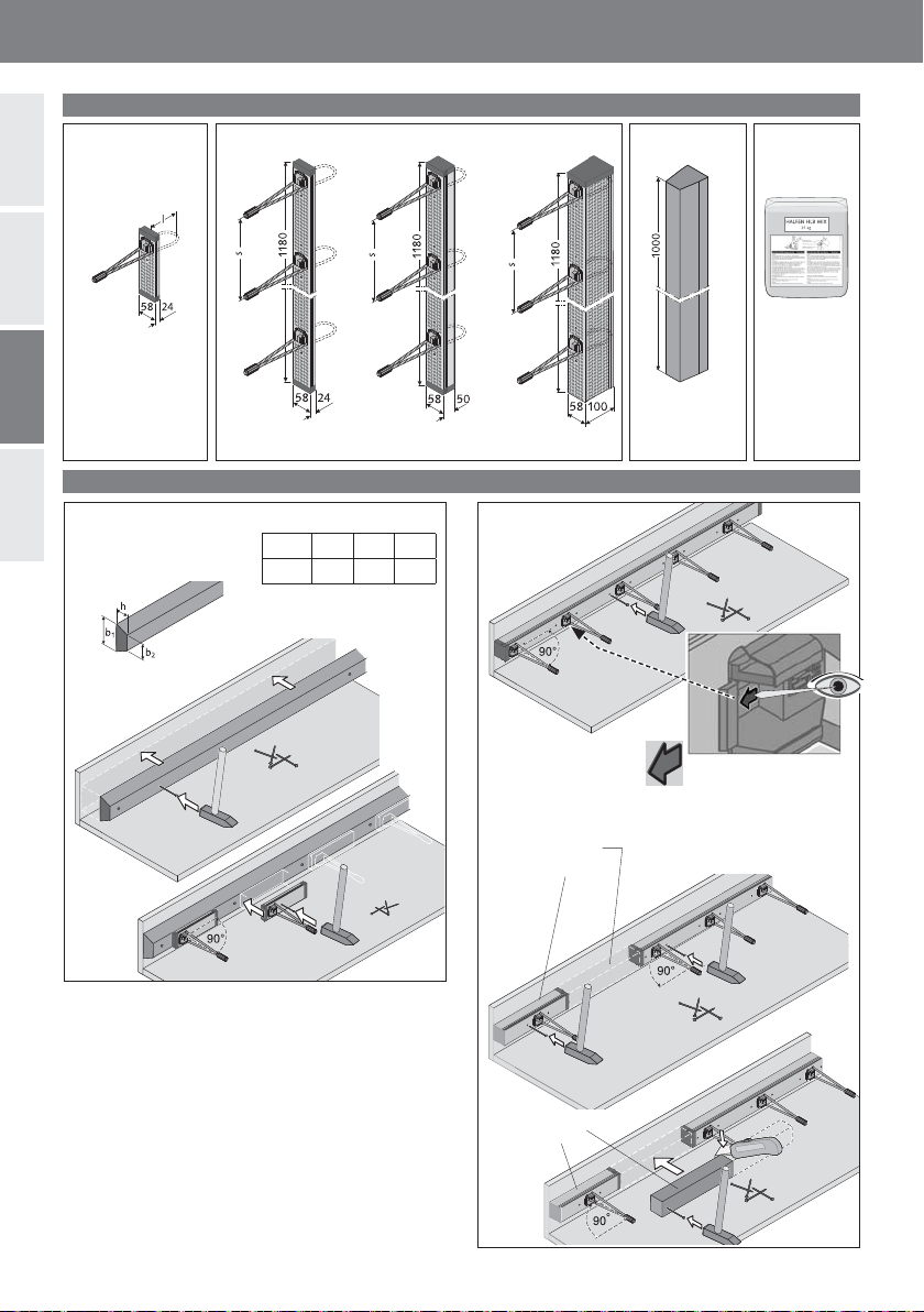
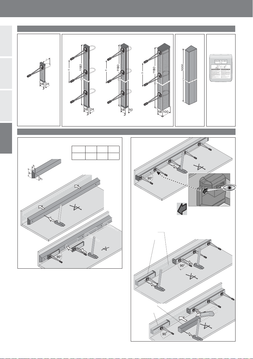
Ajustement et mise en place des aciers supplémentaires
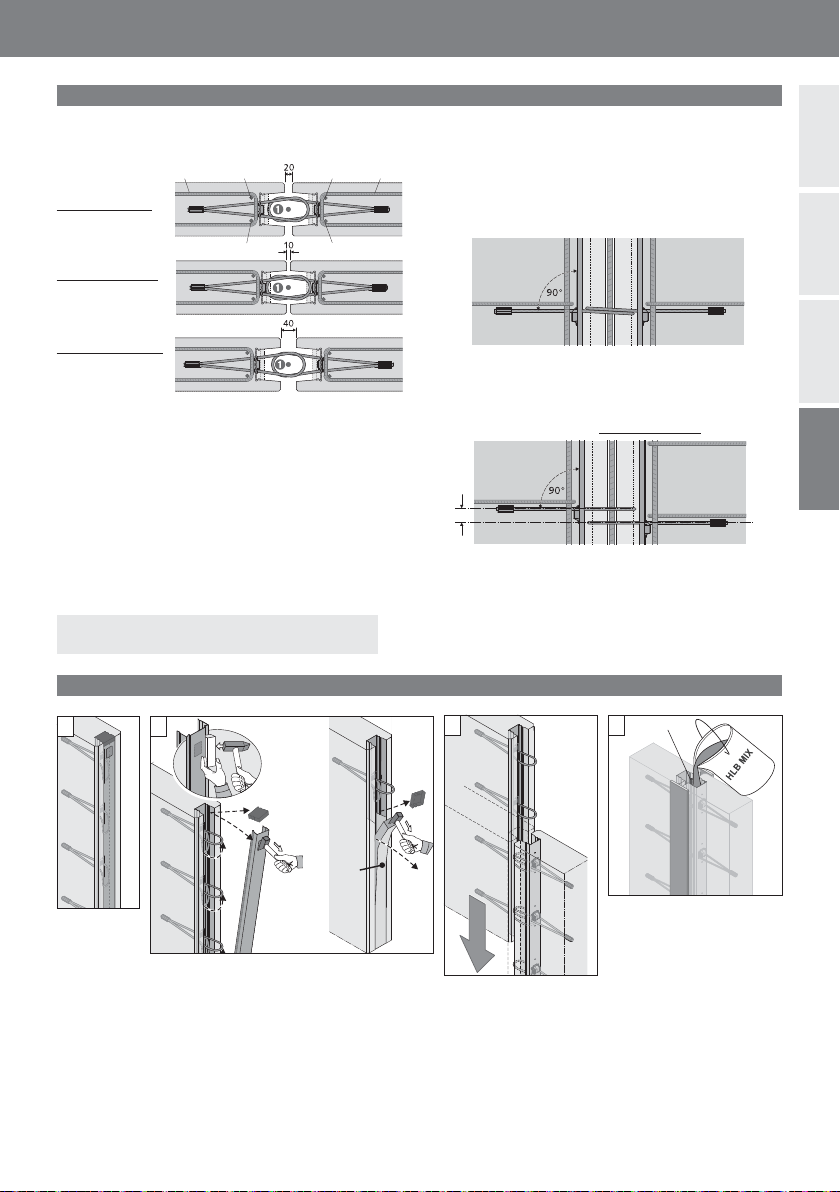
Largeur du joint :
Normal : 20mm
Alignement des boîtiers :
Cas normal : boucles alignées dans l‘axe et au même niveau.
Tolérance verticale : maximum 20mm
Tolérances de construction Suivant l’agrément officiel, ils peuvent êtres utilisés également pour des liaison des constructives.
Mise en place des armatures supplémentaires:
Le armatures supplémentaires doivent être mises en place
conformément aux schémas et elles doivent êtres fixées
aux armatures structurelles
Coupe horizontale : Coupe verticale :
Barre en acier B500A, Ø12mm
Une tolérance verticale de 20mm maximum est autorisée.
Les boucles n’ont pas besoin d’être ligaturées.
Barre en acier B500A, Ø10mm
Etrier en acier B500A, Ø 8 mm, ancrages selon la
DIN 1045-1
La soudure sur les élements HLB n’est pas autorisée !
Minimum:10mm
Maximum: 40mm
1.
1. Elément
préfabriqué
avec un boî-
tier à boucle
HLB.
3.
3. Installation de l’élé-
ment préfabriqué adja-
cent. Toutes les boucles
doivent être relevées per-
pendiculairement au joint,
après avoir été pliée lors
de la mise en place de
l’élément préfabriqué,
elles doivent se relever
automatiquement.
4.
4. Insérer un acier d’armature
de Ø12mm et coffrer le
joint avec les matériaux ap-
propriés. Préparer le mortier
de joint HLB MIX en suivant
les préconisations du fabri-
cant. La hauteur maximale de
coulage est de 3,5 m, sinon
utilisez un tuyau.
Le mortier HLB MIX est
fluide et n’a pas besoin d’être
vibré.
2.
2. Retirer le couvercle du boîtier HLB : extraire
le couvercle du béton comme montré dans le
schéma. Enfoncé le trou pré-percé dans le cou-
vercle en acier. Enlever les scotchs aux extrémi-
tés. Si des prolongateurs HLB sont incorporés,
ils doivent être retirés à l’aide d’un outils ap-
proprié (comme un marteau de charpentier) et
entièrement extraits.
HLB
Spacer
Sur le chantier
max.
20 mm

8© 2015 HALFEN · Inst_HLB 06/15 · www.halfen.com
HLB Instrukcja montażu
Deutsch EnglishFrançaisPolski
Oznakowanie
HLB S
Element jednopętlowy
HLB M 20 HLB M 50 HLB M 100
Element wielopętlowy
HLB Spacer 20
HLB Spacer 50
HLB Spacer 100
Wkładka HLB
(patrz instrukcja
przygotowania
HLB MIX.)
Zaprawa
zalewowa
HLB MIX
Przymocowanie do deskowania
Element jednopętlowy
Przycinanie elementów pośrednich z tworzywa sztucznego:
zmierzyć wymaganą długość wkładki i dociąć na wymiar.
Deskowanie drewnianie:
▪ Przybicie gwoździami
▪ Klejenie (taśma, klej na gorąco)
Deskowanie stalowe:
▪ Klejenie (taśma, klej na gorąco)
▪ Magnetyczne elementy mocujące
▪ Listwa trapezowa
(wykonawca)
▪ Element HLB
*) W zależności od dł. pętli l
[mm] b1b2h
HLB S >55 55 *)
HLB wkładka
HLB Loop Box
HLB wkładka
HLB Loop Box
Element wielopętlowy
Element wielopętlowy + wkładka
Strzałka = kierunek
montażu, góra prefabrykatu

9
© 2015 HALFEN · Inst_HLB 06/15 · www.halfen.com
HLB Instrukcja montażu
Deutsch EnglishFrançaisPolski
Ustawianie prefabrykatów, montaż dodatkowego zbrojenia
Szer. spoiny:
Typowa: 20 mm
Ustawienie elementów HLB:
Typowe: Ustawienie pętli w jednej płaszczyźnie
Dop. przesunięcie pionowe: maximum 20mm
Tolerancja wbudowania wg Aprobaty Technicznej, zalecane także do zastosowań jako połączenia konstrukcyjne.
Montaż dodatkowego zbrojenia:
Dodatkowe zbrojenie należy wbudować zgodnie z
projektem i przymocować do zbrojenia elementów.
w poziomie: w pionie:
Pręt B500A, Ø 12 mm
Dopuszczalne przesunięcie pionowe max. 20mm,
Wiązanie pętli parami nie jest wymagane
Pręt B500A, Ø 10mm
Strzemię B500A, Ø 8mm, zakotwienie wg EC2
Spawanie elementów HLB jest niedopuszczalne!
Minimum:10mm
Maximum: 40mm
1.
1. Prefabrykat
z zamkniętym
elementem
HLB.
3.
3. Ustawienie
prefabrykatu. Wszystkie
pętle linowe po
ustawieniu prefabrykatu
powinny być usytuowane
prostopadle do
płaszczyzny połączenia.
4.
4. Wstawienie pręta i
szalowanie połączenia.
Przygotować zaprawę HLB
MIX wg instrukcji i
równomiernie wypełnić
połączenie. Maksymalna
wysokość betonowania 3,5 m,
w razie potrzeby stosować
rękaw. Zaprawa HLB MIX jest
konystencji płynnej i nie
wymaga dodatkowego
zagęszczenia.
2. Usunięcie pokrywy HLB: odspoić pokrywę
od betonu zgodnie z rysunkiem. Wybić
oznaczony otwór młotkiem. Wyciągnąć
pokrywę. Usunąć zamknięcia końcowe z taśmy
klejącej. Pętle linowe wyprosują się
samoczynnie. Jeśli wbudowane były wkładki,
należy je usunąć przy pomocy odpowiednich
narzędzi np. młotka ciesielskiego.
2.
HLB
wkładka
Na budowie
max.
20 mm

10 © 2015 HALFEN · Inst_HLB 06/15 · www.halfen.com

NOTES REGARDING THIS DOCUMENT
Technical and design changes reserved. The information in this publication is based
on state-of-the-art technology at the time of publication. We reserve the right to make
technical and design changes at any time. Halfen GmbH shall not accept liability for
the accuracy of the information in this publication or for any printing
errors.
The Quality Management System of Halfen GmbH is certified for
the locations in Germany, France, the Netherlands, Austria, Poland,
Switzerland and the Czech Republic acc. to DIN EN ISO 9001:2008,
Certificate No. QS-281 HH.
Furthermore HALFEN is represented
with sales offices and distributors
worldwide.
Austria HALFEN Gesellschaft m.b.H.
Leonard-Bernstein-Str. 10
1220 Wien
Phone: +43-1-2596770
E-Mail: offi[email protected]
Internet: www.halfen.at
Fax: +43-1-259-677099
Belgium /
Luxembourg
HALFEN N.V.
Borkelstraat 131
2900 Schoten
Phone: +32-3-6580720
E-Mail: [email protected]
Internet: www.halfen.be
Fax: +32-3-6581533
China HALFEN Construction Accessories Distribution Co.Ltd.
Room 601 Tower D, Vantone Centre
No.A6 Chao Yang Men Wai Street
Chaoyang District
Beijing · P.R. China 100020
Phone: +86-1059073200
E-Mail: [email protected]
Internet: www.halfen.cn
Fax: +86-1059073218
Czech Republic HALFEN s.r.o.
Business Center Šafránkova
Šafránkova 1238/1
155 00 Praha 5
Phone: +420-311-690060
E-Mail: [email protected]
Internet: www.halfen-deha.cz
Fax: +420-235- 314308
France HALFEN S.A.S.
18, rue Goubet
75019 Paris
Phone: +33-1-44523100
E-Mail: [email protected]
Internet: www.halfen.fr
Fax: +33-1- 44523152
Germany HALFEN Vertriebsgesellschaft mbH
Liebigstr. 14
40764 Langenfeld
Phone: +49-2173-9700
E-Mail: [email protected]
Internet: www.halfen.de
Fax: +49-2173- 970225
Italy HALFEN S.r.l. Soc. Unipersonale
Via F.lli Bronzetti N° 28
24124 Bergamo
Phone: +39-035-0760711
E-Mail: [email protected]
Internet: www.halfen.it
Fax: +39-035-0760799
Netherlands HALFEN b.v.
Oostermaat 3
7623 CS Borne
Phone: +31-74-2671449
E-Mail: [email protected]
Internet: www.halfen.nl
Fax: +31-74-2672659
Norway HALFEN AS
Postboks 2080
4095 Stavanger
Phone: +47-51 823400
E-Mail: [email protected]
Internet: www.halfen.no
Fax: +47-51 823401
Poland HALFEN Sp. z o.o.
Ul. Obornicka 287
60-691 Poznan
Phone: +48-61-6221414
E-Mail: [email protected]
Internet: www.halfen.pl
Fax: +48-61 -6221415
Sweden Halfen AB
Vädursgatan 5
412 50 Göteborg
Phone: +46-31-985800
E-Mail: [email protected]
Internet: www.halfen.se
Fax: +46-31-985801
Switzerland HALFEN Swiss AG
Hertistrasse 25
8304 Wallisellen
Phone: +41-44-8497878
E-Mail: [email protected]
Internet: www.halfen.ch
Fax: +41-44-8497879
United Kingdom /
Ireland
HALFEN Ltd.
A1/A2 Portland Close
Houghton Regis LU5 5AW
Phone: +44-1582-470300
E-Mail: [email protected]
Internet: www.halfen.co.uk
Fax: +44-1582-470304
United States of
America
HALFEN USA Inc.
8521 FM 1976
P.O. Box 547
Converse, TX 78109
Phone: +1 800.423.91 40
E-Mail: [email protected]
Internet: www.halfenusa.com
Fax: +1 877 . 683.4910
For countries not
listed
HALFEN International
HALFEN International GmbH
Liebigstr. 14
40764 Langenfeld / Germany
Phone: +49 -2173 - 970-0
E-Mail: [email protected]
Internet: www.halfen.com
Fax:+49- 2173-970 -849
CONTACT HALFEN WORLDWIDE
HALFEN is represented by subsidiaries in the following 14 countries, please contact us:
Please contact us: www.halfen.com

© 2015 HALFEN GmbH, Germany
applies also to copying in extracts.
U - 306 - 06/15 PDF 06/15
506
This manual suits for next models
8
Table of contents
Languages:
Other Halfen Industrial Equipment manuals